EP0473017B1 - Druckvorrichtung - Google Patents
Druckvorrichtung Download PDFInfo
- Publication number
- EP0473017B1 EP0473017B1 EP91113679A EP91113679A EP0473017B1 EP 0473017 B1 EP0473017 B1 EP 0473017B1 EP 91113679 A EP91113679 A EP 91113679A EP 91113679 A EP91113679 A EP 91113679A EP 0473017 B1 EP0473017 B1 EP 0473017B1
- Authority
- EP
- European Patent Office
- Prior art keywords
- data
- print data
- external device
- image forming
- received
- Prior art date
- Legal status (The legal status is an assumption and is not a legal conclusion. Google has not performed a legal analysis and makes no representation as to the accuracy of the status listed.)
- Expired - Lifetime
Links
- 238000000034 method Methods 0.000 claims description 132
- 239000000872 buffer Substances 0.000 description 54
- 238000011161 development Methods 0.000 description 6
- 238000012546 transfer Methods 0.000 description 5
- 238000012545 processing Methods 0.000 description 4
- 230000005856 abnormality Effects 0.000 description 2
- 238000010276 construction Methods 0.000 description 2
- 238000010586 diagram Methods 0.000 description 2
- 230000006870 function Effects 0.000 description 2
- 230000005540 biological transmission Effects 0.000 description 1
- 239000007853 buffer solution Substances 0.000 description 1
- 238000004891 communication Methods 0.000 description 1
Images


Classifications
-
- G—PHYSICS
- G06—COMPUTING; CALCULATING OR COUNTING
- G06K—GRAPHICAL DATA READING; PRESENTATION OF DATA; RECORD CARRIERS; HANDLING RECORD CARRIERS
- G06K15/00—Arrangements for producing a permanent visual presentation of the output data, e.g. computer output printers
-
- G—PHYSICS
- G06—COMPUTING; CALCULATING OR COUNTING
- G06K—GRAPHICAL DATA READING; PRESENTATION OF DATA; RECORD CARRIERS; HANDLING RECORD CARRIERS
- G06K2215/00—Arrangements for producing a permanent visual presentation of the output data
- G06K2215/0002—Handling the output data
- G06K2215/0005—Accepting output data; Preparing data for the controlling system
-
- G—PHYSICS
- G06—COMPUTING; CALCULATING OR COUNTING
- G06K—GRAPHICAL DATA READING; PRESENTATION OF DATA; RECORD CARRIERS; HANDLING RECORD CARRIERS
- G06K2215/00—Arrangements for producing a permanent visual presentation of the output data
- G06K2215/0082—Architecture adapted for a particular function
Definitions
- the present invention relates to a printing apparatus connectable to a plurality of external devices; as defined in the precharacterizing part of claim 1.
- printing apparatus for forming copy images based on print data transmitted from a personal computer, word processor or similar data processing device (hereinafter referred to as the "host"). Furthermore, printing apparatus connectable to a plurality of hosts have also been provided. The printing apparatus connectable to a plurality of hosts is provided a plurality of connectors for external device input, and print data input from the plurality of hosts to the printing apparatus can be accomplished by connecting signal cables between the aforesaid connectors and the various hosts.
- the aforesaid type of printing apparatus allows a single printing apparatus to be commonly used as a printing means by a plurality of hosts without providing a selector for selectably switching among the plurality of host devices connected thereto. Such an arrangement is particularly logical from the perspectives of cost and space requirements.
- printing apparatus have been unable to receive print requests from other hosts while printing print data transmitted from a single printing apparatus in accordance with a print request received therefrom. That is, conventional printing apparatus have a disadvantage inasmuch as during the time that the printing apparatus is being used by a single host, that printing apparatus is unavailable for use by other hosts connected thereto.
- JP-A-59-108143 discloses a printer device used as an output terminal device on a plurality of CPUs and having an output controlling dvice with a multichannel switching function.
- the above printer has a plurality of channel ports respectively connected to a plurality of CPUs, and a channel selection switching circuit.
- the switching circuit checks whether an output request signal from the other channel ports has been already received or not. If the circuit has already received the output request signal from the other channel ports, it sends "Busy" signal to the CPU. If the circuit has not received any output request signal from the other channel ports, it validates the corresponding channel port and sends to the CPU a signal representing allowance of receipt of the output request.
- US-A-4604682 discloses a buffer system for interfacing an intermittently accessing data processor to an independently clocked communication system.
- a transfer control signal generator is adapted to respond to preemption signal provided from a preemption signal generator while a RAM is accessed by the data processor by interrupting its sequential generation of transfer control signals during the interval of the preemption signal and to respond to the termination of the preemption signal by resuming said sequential generation of transfer control signals at the point of interruption.
- a main object of the present invention is to provide a printing apparatus connectable to a plurality of external devices, and which is capable of receiving print requests from other external devices while printing print data transmitted from a single external device in accordance with a print request received therefrom.
- a further object of the present invention is to provide a printing apparatus which, when connected to a first and second host, gives priority to printing print data transmitted from the first host over printing print data transmitted from the second host, said printing apparatus being capable of receiving a print request from the first host when said first host transmits a print request during printing of print data transmitted from the second host.
- a still further object of the present invention is to provide a printing apparatus which, when connected to a plurality of hosts and printing print data transmitted from a first host, is capable of determining whether or not a print request corresponding to print data copy conditions has been received from another host.
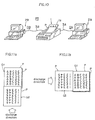
- the printing system PS shown in FIG. 10 comprises a laser printer 1 and two personal computers (hosts) 2A and 2B.
- the laser printer 1 is connected to each host 2A and 2B by means of the cables 3A and 3B, respectively.
- the hosts 2A and 2B transmit print data DA and DB comprising image data expressing character and graphic information, and control data, respectively.
- the laser printer 1 forms images by means of a well known bit map method for writing image data as dot patterns.
- the papers P bearing the formed image thereon are discharged and stacked one sheet at a time on a tray 1a in the main unit.
- FIG. 8 is a block diagram showing the essential construction of the laser printer 1.
- the laser printer 1 comprises a central processing unit (CPU) 11 for controlling all operations, a read only memory (ROM) 12 for storing process programs and the like, a random access memory (RAM) 13 for storing data (described later) and used as bit map memory, interfaces 14A and 14B used for input from external devices, an interrupt controller 16, a print engine 20 for forming images via an electrophotographic process using a laser light source, a print engine interface 18, and a dip switch interface 17.
- CPU central processing unit
- ROM read only memory
- RAM random access memory
- interfaces 14A and 14B used for input from external devices
- an interrupt controller 16 a print engine 20 for forming images via an electrophotographic process using a laser light source
- a print engine interface 18 for forming images via an electrophotographic process using a laser light source
- a print engine interface 18 for forming images via an electrophotographic process using a laser light source
- the print data DA from the host 2A are input to the interface 14A through a connector 15A and a cable 3A.
- the print data DB from the host 2B are input to the interface 14B through a connector 15B and a cable 3B.
- the interrupt controller 16 inputs the print data DA and DB to the interfaces 14A and 14B, and transmits the interrupt to the CPU 11.
- a receiving process (FIG. 7), described later, is executed as the interrupt process via the aforesaid pause request.
- the laser printer 1 of the present embodiment is capable of assigning priority to either one of the interfaces 14A or 14B relative to the other via dip switches not shown in the drawing. That is, one of the interfaces 14A or 14B given precedence receives the print data and when printing is requested, the printing process is temporarily halted even if a printing process is currently being executed for print data of the other interface 14B or 14A, and the printing process of the interface 14A or 14B given priority is executed as a pause process.
- the interface 14A connected to the host 2A is given priority in the following description, the interface 14B connected to the host 2B may alternatively be given priority.
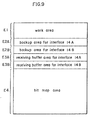
- FIG. 9 is an illustration showing the memory area assignments of the RAM 13.
- the RAM 13 is provided a work area E1 for temporary storage of various set values and parameters every time a printing process is executed, backup areas E2A and E2B for storing the print conditions (fonts, margins and the like) assigned by the print data DA and DB, respectively, receiving buffer areas E3A and E3B corresponding to the interfaces 14A and 14B, and a bit map area E4 for writing one-page image data.
- a work area E1 for temporary storage of various set values and parameters every time a printing process is executed
- backup areas E2A and E2B for storing the print conditions (fonts, margins and the like) assigned by the print data DA and DB, respectively, receiving buffer areas E3A and E3B corresponding to the interfaces 14A and 14B, and a bit map area E4 for writing one-page image data.
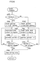
- FIGS. 1a and 1b are a flow chart showing the operation of the CPU 11.
- each portion is initialized based on the switch state read through the ROM 12 data and the dip switch interface 17 (step 11).
- the flags FLAGA, FLAGB, WORKA and WORKB are all set at [0].
- the flags FLAGA, and FLAGB respectively indicate the existence of data in the receiving buffer areas E3A and E3B.
- the aforesaid flags FLAGA and FLAGB are set at [1] when data have been stored in the receiving buffer areas E3A and E3B.
- the flags WORKA and WORKB indicate whether or not image writing is currently executing (on-going dot data development) in the bit map area 4.
- the flag WORKA corresponds to the interface 14A
- the flag WORKB corresponds to the interface 14B.
- step #12 the flag FLAGA is checked to determine the existence of data in receiving buffer area E3A. If the flag FLAGA is set at [0], the flag FLAGB is checked in step #18 to determine the existence of data in the receiving buffer area E3B. If the flag FLAGB is also found to be set at [0], the routine returns to step #12 and the process of steps #12 and #18 are repeated. That is, the entry of the print data DA and DB transmitted from the host 2A or 2B and the storage of said data in the receiving buffer areas E3A or E3B is awaited.
- step #12 If the flag FLAGA is found to be set at [1] in step #12, the flag WORKB is checked in step #13. When the flag WORKB is found to be set at [1] in step #13, one-page image information corresponding to the print request transmitted from the host 2B is currently being written to the bit map area E4, so that the routine moves to step #18 and the aforesaid writing continues.
- step #13 If the flag WORKB is found to be set at [0] in step #13, then the routine continues to step #14 where the flag WORKA is checked. If the flag WORKA is set at [1] in step #14, then the data process A corresponding to the priority interface 14A is executed in step #17.
- step #14 If the flag WORKA is found to be set at [0] in step #14, said flag WORKA is set at [1] in step #15 because data development in bit map area E4 is renewed, or data development of the next page information is started, and the data of the backup area E2A is transferred to the work area E1 in step #16. Next, the data process A is executed in step #17, and the routine returns to step #12 thereafter.
- step #18 the flag WORKA is checked in step #19 to determine whether or not it is set at [0]. If the flag WORKA is found to be set at [0] in step #19, the flag WORKB is checked in step #20 to determine whether or not it is set at [0]. Then, if the flag WORKB is found to be set at [1] in step #20, the data process B corresponding to the interface 14B is executed in step #23.
- step #20 When the flag WORKB is found to be set at [0] in step #20, it is reset at [1] in step #21, and the data of the backup area E3B is transferred to the work area E1 in step #22. Then, the data process B is executed in step #23, and the routine thereafter returns to step #12.
- FIG. 2 is a flow chart for the data process A of step #17 shown in FIG. 1a.
- step #31 data of a specified length (for example, 1 byte) are fetched from the receiving buffer area E3A (step #31).
- step #32 a buffer checking process A is executed in step #32. More specifically, as shown in FIG. 3, input of print data DA to the interface 14A is enabled (step #51), and a ready signal (command data) is output to designate the ready state whereby the laser printer 1 can receive data from the host 2A (step #52). The process in step #51 cancels the input inhibited state occurring when no empty areas remain in the receiving backup area E3A (FULL state).
- the interface 14A is a centronics model, the status of the laser printer 1 as being capable of reception in the ready state can be discriminated by the host 2A state without specifically requiring the output of a ready signal.
- step #33 a check is made in step #33 to determine whether or not the data fetched from the receiving buffer area E3A is command data.
- step #33 the fetched data are not found to be command data, i.e., the fetched data are image data, then the image data are written to the bit map area E4 in step #41.
- the image data to be written are character codes
- the fonts stored in the work area E1 are selected, and the characters corresponding to these character codes are developed as bit data in the bit map area E4 in accordance with the aforesaid selected fonts.
- step #39 a check is made to determine the existence of data in the receiving buffer area E3A, and if data are present the routine returns to step #31. If data are not present, the flag FLAGA is reset at [0] in step #40.
- step #33 when the data fetched in step #33 are determined to be command data and said command data are found in step #34 to be page change codes expressing the page break of each page, the printing process is executed in step #35 wherein data are read from the bit map area E4, data are transmitted to the print engine 20 and the like.
- step #36 If no subsequent data are found in the receiving buffer area E3A in step #36, the flag WORKA is reset at [0] in step #37 to end the printing process, and the data are transferred from the work area E1 to the backup area E2A.
- step #36 the routine returns to step #31 and the next page printing process is executed.
- step #34 When the data fetched from the receiving buffer area E3A in step #34 are found to be command data other than the aforesaid page feed codes, the command processes are executed in step #38 in accordance with said command data.
- FIG. 4 is a flow chart of the data process B of FIG. 1b.
- the backup process B shown in FIG. 5 is executed (steps #61 and #62). Then, a printing process, command process, and writing of the data of bit map area E4 are executed (steps #63, 64, 65, 68 and 71) in accordance with the various data types.
- the flag WORKB is reset at [0] as the print completion process in step #66 without regard to the existence or absence of data in the receiving buffer area E3B, and finally the data transfer from the work area E1 to the backup area E2B is executed.
- the process is temporarily halted every time a one-page segment printing process is completed even when other page segment data remain in the receiving buffer area E3B, then the program returns to the main routine.
- the printing process for the executing host 2B is paused after each page break, or alternatively, the printing process for the host 2A is given priority in execution. Thereafter, when the printing process for the host 2A is completed, and the pause printing process for the host 2B is restarted.
- FIG. 6 is a flow chart of the printing processes of FIGS. 2 and 4.
- the pointer address data are read from the bit map area E4 and transmitted to the print engine 20, whereupon the pointer is incremented.
- the aforesaid process is repeated until the bottom address of the bit map area E4 is reached (steps #87, 88 and 89).
- the bit map area E4 is cleared when the reading of the data from all parts of the bit map area E4 has been completed (step #94).
- the reading of the bit map area E4 is accomplished according to the synchronization signals transmitted from the print engine 20 and in correspondence with the margin values stored in the work area E1.
- the photosensitive member in the print engine 20 is exposed to flashing light from a laser light source.
- bit map area E4 is cleared when the reading of the data from all parts of the bit map area E4 has been completed (step #94).
- the data are read in the same sequence as the writing sequence from the top address to the bottom address of the bit map area E4.
- the data of the bit map area E4 is read in the reverse to the writing sequence when printing for the host 2B.
- FIG. 11a shows an example wherein the orientations of the images G1 and G2 coincide with the discharge direction of the sheets P
- FIG. 11b shows an example wherein the orientations of the images G1 and G2 are perpendicular to the discharge direction of the sheets P.
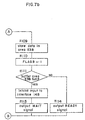
- FIGS. 7a and 7b are a flow chart of the receiving process.
- the main routine of the receiving process is executed whenever required as the pause routine of the main routine of FIG. 1 in correspondence with the input of print data DA and DB to the interfaces 14A and 14B.
- the CPU 11 checks to determine whether the reception is from the interface 14A or 14B in step #102. If the reception is found to be from the interface 14A in step #102, then the print data DA are stored in the receiving buffer area E3A in step #103, and the flag FLAGA is set to [1] in step #104.
- step #105 the receiving buffer area E3A is checked in step #105 to determine whether or not it is full. If the buffer area is not full, a ready signal is output to the host 2A in step #108, whereas if the buffer area E3A is full in step #105, input is inhibited to the interface 14A in step #106. A wait signal is output in step #107 to alert the host 2A to the full buffer condition.
- the print data DB are stored in the receiving buffer area E3B in step #109, and the flag FLAGB is set at [1] in step #110.
- step #111 When the receiving buffer area E3B is not found to be full in step #111, a ready signal is output to the host 2B, whereas when the buffer area E3B is full in step #111, output to the interface 14B is inhibited in step #112, and a wait signal is output to the host 2B in step #113.
- FIG. 12 is a flow chart showing the operations of the hosts 2A and 2B.
- step #201 After the print data DA and DB are created in step #201, said print data DA and DB having a specified length are output to the laser printer 1 in step #202, i.e., a print request is issued.
- step #203 the status of the laser printer 1 is read in step #203, and if an error state exists wherein the status indicates a reception abnormality in step #204, then an error process corresponding to the type of error is executed in step #209. If the status does not indicate an error state in step #204, then a wait state obtains in step #205, and the status of the laser printer 1 is read again in step #206, and the ready state is awaited in step #207.
- step #208 the existence of print data DA and DB for transmission is checked in step #208. If data exists, the routine returns to step #202 and the next data are transmitted.
- priority was assigned to the interface 14A over the interface 14B by means of dip switches. Accordingly, when print data were input to the priority interface 14A and a print request issued during an on-going printing process for the interface 14B, the printing process for the interface 14B is temporarily paused and the printing process of the interface 14A is executed as an interrupt process. When print data are input to the interface 14B, which does not have priority, and a print request is issued during an on-going printing process for the interface 14A, the printing process for the interface 14B is not executed as an interrupt process.
- the printing process for the interface 14B is executed as an interrupt process in accordance with the specified printing conditions (copy number and the like). Furthermore, the parameters for the reference values for allowing a pause in the printing process can be suitable selected.
- the second embodiment of the invention provides a function allowing an interrupt process in the printing process for a non-priority interface in accordance with the specified printing conditions in the printing system PS of the first embodiment. Accordingly, the second embodiment is identical to the first embodiment except for the steps relating to the number of remaining sheets to be printed (the number of sheets specified at the start of the printing process) in the printing process of the hosts 2A and 2B, i.e., the CPU operations (FIG. 1), data process A (FIG. 2), data process B (FIG. 4), receiving process (FIGS. 7a and 7b), and host process (FIG. 12).
- the CPU operations (FIGS. 13a and 13b), data process A (FIG. 14), data process B (FIG. 15), receiving process (FIGS. 16a and 16b) and host process (FIG. 17) of the second embodiment are described using only the pertinent flow charts.
- FIGS. 13a and 13b are a main flow chart showing the operation of the CPU 11.
- each portion of the system is initialized based on the data in ROM 12 and the switch states read through the dip switch interface 17 (step #311).
- the flags FLAGA, FLAGB, WORKA, WORKB, and the counters CNTA and CNTB are reset at [0], and the value of the parameter PARA is set at, for example, [10].
- the flags FLAGA and FLAGB respectively indicate the presence or absence of data in the receiving buffer areas E3A and E3B. These flags are set at [1] when data are stored in the receiving buffer areas E3A and E3B in a receiving process described later.
- the flags WORKA and WORKB indicate whether or not an image is being written (currently on-going dot data development) to the bit map area E4.
- the flag WORKA corresponds to the interface 14A
- the flag WORKB corresponds to the interface 14B.
- the counters CNTA and CNTB indicate the number of remaining copies to be printed (number of copies specified at the start of printing).
- the counter CNTA corresponds to the interface 14A
- the counter CNTB corresponds to the interface 14B.
- step #312 the counter CNTB is checked (step #312).
- the routine moves to step #314.
- CNTA and CNTB are the values for the counters CNTA and CNTB, and PARA is the value of the parameter PARA; the value of the parameter PARA is "10" at this time.
- the print request of the host 2B is executed and the routine moves to step #320.
- the latter print request is executed first if the number of sheets to be printed are fewer than the remaining sheets to be printed in the on-going printing process.
- the difference between the specified number of sheets by the host 2B and the remaining sheets in the on-going printing process must be greater than the value of the parameter PARA as shown in equation (1). Accordingly, the host 2A is given priority over the host 2B.
- step #314 the flag FLAGA is checked for the existence of data in receiving buffer area E3A. If the flag FLAGA is set at [0], the routine continues to step #320 where the flag FLAGB is checked for the existence of data in the receiving buffer area E3B. If the flag FLAGB is found to be set at [0] in step #320, the routine returns to step #312, i.e., the storage of the print data DA or DB from the hosts 2A or 2B in the receiving buffer areas E3A or E3B is awaited.
- step #314 If the flag FLAGA is set at [1] in step #314, the flag WORKB is checked in step #315. If the flag WORKB is found to be set at [1] in step #315, the routine moves to step #320 because a one-page segment image corresponding to the print request from the host 2B is being written to the bit map area E4, and the writing process continues uninterrupted.
- step #315 When the flag WORKB is found to be set at [0] in step #315, the routine continues to step #316 where the flag WORKA is checked. If the flag WORKA is set at [1] in step #316, then the data process A for the priority interface 14A is executed.
- step #316 If the flag WORKA is found to be set at [0] in step #316, the flag WORKA is reset at [1] in step #317 because data development to the bit map area E4 is started anew, or the data development of the next page segment is started. Then, the data of the backup area E2A is transferred to the work area E1 in step #318. After the data process A has been executed in step #319, the routine returns to step #312.
- step #321 when the flag FLAGB is found to be set at [1] in the aforementioned step #320, the flag WORKA is checked in step #321. If the flag WORKA is found to be set at [0] in step #321, the flag WORKB is checked in step #322. When the flag WORKB is set at [1] in step #322, the data process B for the interface 14B is executed in step #325.
- step #322 if the flag WORKB is found to be set at [0] in step #322, it is reset at [1] in step #323, and the data in backup area E3B is transferred to the work area E1 in step #324. After the data process B has been executed in step #325, the routine returns to step #312.
- FIGS. 14a and 14b are a flow chart of the data process A of step #319 in FIG. 13a.
- step #331 data of a specified length (for example, 1 byte) are fetched from the receiving buffer area E3A (step #331).
- the buffer check process A of the present embodiment is identical to that described in the first embodiment (refer to FIG. 3) and is, therefore, omitted herefrom.
- step #333 the data fetched from the receiving buffer area E3A are checked to determine whether or not said data are command data.
- the fetched data are not command data, i.e., if the fetched data are image data, said image data are written to the bit map area E4 (step #343).
- the image data to be written are character codes, fonts stored in the work area E1 are selected, and the characters relating to the character codes are developed as bit data in the bit map area E4 in accordance with the selected fonts.
- the receiving buffer area E3A is checked for the presence of data in step #341. If data are present, the routine returns to step #331, whereas if data are absent, the flag FLAGA is reset at [0] in step #342.
- step #333 if the data fetched in step #333 are found to be command data, said command data are found to be page change codes indicating page breaks for each page in step #334, and print processes such as reading the data from the bit map area E4 and data transference to the print engine 20 and the like are executed in step 335. Subsequently, in step #336, the flag WORKA is set at [0] as the print completion process, and the data are transferred from the work area E1 to the backup area E2A.
- step #337 If the counter CNTA is not found to be set at [0] in step #337, said counter CNTA is decremented in step #338. If the next data in the receiving buffer area E3A is found to be absent in step #339, the routine continues to step #342 previously described.
- step #334 When the data fetched from the receiving buffer area E3A are found to be command data other than page change codes in step #334, the command processes are executed in accordance with the command data in step #340.
- FIG. 15 is a flow chart of the data process B in FIG. 13b.
- the data process B is executed in the same way as the previously described data process A except the data in the receiving buffer area E3B are the objects of processing.
- the buffer check process B is executed in step #362. Since the buffer check process B of the present embodiment is identical to the process described for the first embodiment (refer to FIG. 5), a further description is omitted herefrom. Then, a printing process, command process, and writing of the data of bit map area E4 are executed (steps #365, 370, and 373) in accordance with the various data types, in the same way as in the data process A shown in FIG. 14 (steps #363 and 364).
- step #365 After the print process in step #365 is completed, the flag WORKB is reset at [0], the data are transferred from the work area E1 to the backup area E2B, the counter CNTB is checked and decremented, then the receiving buffer area E3B is checked (steps #366 to 369). Furthermore, after the command process in step #370, or writing to the bit map area E4 in step #373, the receiving buffer area E3B is checked and the flag FLAGB is reset at [1] (steps #371 and 372).
- FIGS. 16a and 16b are a flow chart of the receiving process of the second embodiment.
- the CPU 11 checks for signals from either the interface 14A or 14B (steps #401 and 402). If signals from the interface 14A are found in step #402, and if data received by the interface 14A are the sheet number commands specifying the number of copies to be printed, then the specified number is set in the counter CNTA in accordance with the sheet number command specifying the number of copies to be printed in step #404.
- step #406 If the data received from the interface 14A is data other than sheet number commands, said data are stored in the receiving buffer area E3A in step #406, and the flag FLAGA is set at [1] in step #407.
- step #408 a check is made in step #408 to determine whether or not the receiving buffer area E3A is full. If the buffer area E3A is not full, a ready signal is output to the host 2A in step #405. If the buffer area E3A is found to be full in step #408, the input of data to the interface 14A is inhibited in step #409, and a wait signal is output in step #410 to alert the host 2A that data input to the interface 14A is inhibited.
- step #402 when reception from the interface 14B is determined in step #402, and when the received data is found to be sheet number commands in step #411, the specified number of copies is set in the counter CNTB in accordance with the sheet number commands in step #417. If the data received by the interface 14B are data other than the sheet number commands, said data are stored in the receiving buffer area E3B in step #412, and the flag FLAGB is set at [1] in step #413.
- step #414 If the receiving buffer area E3B is not full in step #414, a ready signal is output to the host 2B in step #418. If the receiving buffer area E3B is full in step #414, however, a wait signal is output to the host 2A in step #416, after further input to the interface 14A is inhibited in step #415.
- FIG. 17 is a flow chart showing the operations of the hosts 2A and 2B.
- the sheet number commands are output to the laser printer 1 (steps #501 and 502). Then, the status of the laser printer 1 is read in step #503. If the read status is found to be an error state indicating a reception abnormality in step #504, an error process is executed in step #505.
- step #504 If no error state is found in step #504, the print data DA and DB of a specified data length are output to the laser printer 1 in step #505. Then, the status of the laser printer 1 is again read in step #506. If the status does not indicate an error state in step #507, and said status is found to be a wait state in step #508, the laser printer 1 status is read again in step #509, and a ready state is awaited in step #510.
- step #510 When a ready state is found in step #510, a check is made to detect the existence of the print data DA and DB in step #511. If print data for output exist, the routine returns to step #505, and the next data are output.
- step #66 of the data process B corresponds to the operation of the print pause means
- steps #12 through 17 correspond to the operation of the interrupt printing means
- step #12 and steps #18 through 23 correspond to the operation of the resume printing means.
- step #313 corresponds to the operation of the interrupt allowing means during printing
- steps #336 and 366 correspond to the operation of the pause means during printing
- steps #314 through 325 correspond to the operation of the interrupt printing means and the resume printing means.
- an interrupt for a subsequent printing process is allowed by satisfying the condition of equation (1) in the second embodiment, said interrupt may be allowed by suitably selected reference criteria.
- the copy number specified during printing and the number of remaining sheets to be printed may be respectively designated N1 and n1
- the copy number specified for a subsequent print request may be designated N2, such that an interrupt may be allowed by conditional equations such as N2 ⁇ N1, N2 ⁇ n1, N2 ⁇ a specified number of sheets (for example, several pages), N1-N2> a specified number of sheets, n1-N2> a specified number of sheets, and the like.
- an interrupt may be disabled when N1 or n1 is less than a predetermined number of sheets.
- selections such as paper size, fonts and the like that does not require paper replacement or font transfers can be used as criteria for other printing conditions in the second embodiment.
- the number of sheet for printing and other print conditions may also be used in suitable combinations.
- the value of the parameter PARA is not restricted to the value "10" used as an example in the second embodiment, and may be modified according to the conditions under which the printing system PS is used. Furthermore, degrees of priority may be provided between the interface 14A and the interface 14B.
- the printing system of the present invention provides that when print data DA are input from the host 2A during an on-going printing process for the host 2B, the executing printing process can be paused at every page break, and can pause during a one page process without wasting paper P.
- the printing system of the present invention further allows that when print conditions are pre-stored in the backup areas E2A and E2B during a pause in the printing process for hosts 2A and 2B, the print conditions to be read from the backup areas E2A and E2B when restarting said printing processes.
- This arrangement allows readily accelerates the printing operation without increasing the work load of the operator because the print conditions need not be reset when restarting the printing process after pausing.
- key switches or the like may also be provide on an operation panel for setting priority rankings between the interfaces 14A and 14B. This arrangement may be very convenient for the operator if a means for indicating the set priority rankings is provided on the operation panel. Furthermore, operating efficiency may be improved when connecting (setting up) hosts 2A and 2B if the priority rankings are displayed near the connectors 15A and 15B via LEDs or the like.
- the printing processes of the interfaces 14A and 14B may be interrupted equally without setting a priority ranking.
- priority ranking between the interfaces 14A and 14B were changeable via dip switches in the first and second embodiment, said priority ranking may alternatively be made fixed. In such an instance, giving priority to interfaces 14A and 14B corresponding to the connectors 15A and 15B on the right side viewed form the front of the laser printer 1 enhances operation characteristics and accessible cable connections for cables 3A and 3B so as to be generally advantageous.
- laser printer 1 connectable to two hosts 2A and 2B was used as an example in the first and second embodiments, said laser printer may alternatively be connectable to three or more external devices.
Claims (6)
- Druckvorrichtung (1) mit einer Bilderzeugungseinrichtung (20) zum Erzeugen von Bildern auf der Grundlage von Druckdaten (DB, DA), die von einem ersten und zweiten äußeren Gerät (2B, 2A) übertragen werden,
dadurch gekennzeichnet, daß sie weiter aufweist:eine Hemmeinrichtung (11) zum automatischen Hemmen eines momentan von der Bilderzeugungseinrichtung (20) durchgeführten Bilderzeugungsvorgangs bei einem Seitenumbruch, wenn die Druckdaten (DA) von dem zweiten äußeren Gerät (2A) während des Bilderzeugungsvorgangs, der auf den von dem ersten äußeren Gerät (2B) übertragenen Druckdaten beruht, übertragen werden, wobei den von dem zweiten äußeren Gerät (2A) übertragenen Druckdaten Priorität gegenüber den von dem ersten äußeren Gerät (2B) übertragenen Druckdaten gegeben wird, so daß die Hemmeinrichtung den momentanen Bilderzeugungsvorgang nur dann hemmen kann, wenn Druckdaten (DA) von dem zweiten äußeren Gerät (2A) während eines Bilderzeugungsprozesses, der auf den von dem ersten äußeren Gerät (2B) empfangenen Druckdaten (DB) beruht, übertragen werden,eine Interrupt-Einrichtung (11) zum Ausführen des Bilderzeugungsvorgangs auf der Grundlage der von dem zweiten äußeren Gerät (2A) empfangenen Druckdaten (DA), nachdem die Hemmeinrichtung (11) den Druckvorgang, der momentan auf der Grundlage der vom ersten äußeren Gerät (2B) empfangenen Druckdaten (DB) durchgeführt wurde, gehemmt hat, und eine Wiederaufnahmeeinrichtung (11) zum Wiederaufnehmen des Bilderzeugungsvorgangs auf der Grundlage der vom ersten äußeren Gerät (2B) empfangenen Druckdaten (DB) nach Beendigung des Bilderzeugungsvorgangs, der von der Interrupteinrichtung (11) auf der Grundlage der vom zweiten äußeren Gerät (2) empfangenen Druckdaten (DA) ausgeführt wird. - Druckvorrichtung (1) nach Anspruch 1,
bei der das erste und zweite äußere Gerät (2B, 2A) mit der Druckvorrichtung (11) über erste und zweite Verbindungen (14B, 15B und 14A, 15A) verbunden sind, wobei die zweite Verbindung (14A, 15A) Priorität gegenüber der ersten Verbindung (14B, 15B) hat, so daß die über die zweite Verbindung (14A, 15A) empfangenen Druckdaten (DA) Priorität gegenüber den über die erste Verbindung (14B, 15B) empfangenen Druckdaten haben. - Druckvorrichtung (1) nach Anspruch 2,
die ferner Mittel zum Umschalten der Priorität von der zweiten Verbindung (14A, 15A) zu der ersten Verbindung (14B, 15B), oder umgekehrt, aufweist. - Druckvorrichtung nach Anspruch 1,die ferner aufweist:eine Freigabeeinrichtung zum Freigeben des Interrupt des Bilderzeugungsvorgangs der von dem zweiten äußeren Gerät (2A) empfangenen Druckdaten (DA) entsprechend den Bild-erzeugungsbedingungen der von dem zweiten äußeren Gerät (2A) empfangenen Druckdaten (DA), wenn die Druckdaten von dem zweiten äußeren Gerät (2A) während eines Bilderzeugungsvorgangs aufgrund der von dem ersten äußeren Gerät (2B) empfangenen Druckdaten (DB) empfangen werden.
- Druckvorrichtung nach Anspruch 4,
bei dem die Freigabeeinrichtung den Interrupt des Bild-erzeugungsvorgangs der von dem zweiten äußeren Gerät (2A) empfangenen Druckdaten (DA) gemäß mindestens einer der folgenden Bilderzeugungsbedingungen freigibt: Anzahl der Druckseiten, Format des Druckpapiers und Schriftzeichenfond. - Druckvorrichtung nach Anspruch 1,
bei der die Bilderzeugungsbedingungen der von dem ersten äußeren Gerät (2B) empfangenen Druckdaten (DB) in einem Speicher (E2B) gespeichert werden, wenn die Druckdaten (DA) von dem zweiten äußeren Gerät (2A) während des auf den vom ersten äußeren Gerät (2B) empfangenen Druckdaten (DB) beruhenden Bilderzeugungsvorgangs empfangen werden.
Applications Claiming Priority (4)
| Application Number | Priority Date | Filing Date | Title |
|---|---|---|---|
| JP231193/90 | 1990-08-31 | ||
| JP2231193A JPH04111114A (ja) | 1990-08-31 | 1990-08-31 | プリンタ装置 |
| JP231195/90 | 1990-08-31 | ||
| JP23119590A JP2792216B2 (ja) | 1990-08-31 | 1990-08-31 | プリンタ装置 |
Publications (3)
| Publication Number | Publication Date |
|---|---|
| EP0473017A2 EP0473017A2 (de) | 1992-03-04 |
| EP0473017A3 EP0473017A3 (en) | 1993-03-10 |
| EP0473017B1 true EP0473017B1 (de) | 1997-05-28 |
Family
ID=26529744
Family Applications (1)
| Application Number | Title | Priority Date | Filing Date |
|---|---|---|---|
| EP91113679A Expired - Lifetime EP0473017B1 (de) | 1990-08-31 | 1991-08-14 | Druckvorrichtung |
Country Status (3)
| Country | Link |
|---|---|
| US (1) | US5930462A (de) |
| EP (1) | EP0473017B1 (de) |
| DE (1) | DE69126259T2 (de) |
Families Citing this family (6)
| Publication number | Priority date | Publication date | Assignee | Title |
|---|---|---|---|---|
| JP3486467B2 (ja) * | 1993-10-21 | 2004-01-13 | キヤノン株式会社 | 画像記録装置及びその制御方法 |
| US6130757A (en) * | 1996-05-21 | 2000-10-10 | Minolta Co., Ltd. | Client-server system with effectively used server functions |
| JP3707339B2 (ja) | 2000-03-16 | 2005-10-19 | コニカミノルタビジネステクノロジーズ株式会社 | 画像形成装置 |
| JP2003122526A (ja) * | 2001-08-07 | 2003-04-25 | Canon Inc | ジョブに基づいて画像処理を行う画像処理装置、またはジョブの処理順序を制御する制御方法 |
| US20060069825A1 (en) * | 2004-09-24 | 2006-03-30 | Hodder Leonard B | Method and system of transferring firmware from a host device to a printing device |
| JP4183717B2 (ja) * | 2006-04-06 | 2008-11-19 | シャープ株式会社 | 画像処理装置 |
Family Cites Families (13)
| Publication number | Priority date | Publication date | Assignee | Title |
|---|---|---|---|---|
| US4623244A (en) * | 1976-10-04 | 1986-11-18 | International Business Machines Corporation | Copy production machines |
| US4273439A (en) * | 1979-07-09 | 1981-06-16 | International Business Machines Corporation | Document feeder system having a suspending/commencing mode with a judgment decision capability |
| US4527885A (en) * | 1981-07-15 | 1985-07-09 | Canon Kabushiki Kaisha | Image recording system having multiple image recording means |
| US4604682A (en) * | 1982-09-30 | 1986-08-05 | Teleplex Corporation | Buffer system for interfacing an intermittently accessing data processor to an independently clocked communications system |
| US4754428A (en) * | 1985-04-15 | 1988-06-28 | Express Communications, Inc. | Apparatus and method of distributing documents to remote terminals with different formats |
| US5014221A (en) * | 1988-01-29 | 1991-05-07 | Digital Equipment Corporation | Mechanism for arbitrating client access to a networked print server |
| JP2755622B2 (ja) * | 1988-10-24 | 1998-05-20 | 株式会社東芝 | 画像形成装置 |
| US5075874A (en) * | 1989-04-10 | 1991-12-24 | Eastman Kodak Company | Communications interface for computer output printer |
| JPH0335863A (ja) * | 1989-06-30 | 1991-02-15 | Mazda Motor Corp | エンジンのシリンダブロック構造 |
| US4947345A (en) * | 1989-07-25 | 1990-08-07 | Xerox Corporation | Queue management system for a multi-function copier, printer, and facsimile machine |
| US5164842A (en) * | 1990-06-29 | 1992-11-17 | Xerox Corporation | Job/page proofing for electronic printers |
| US5113355A (en) * | 1990-10-10 | 1992-05-12 | Fuji Xerox Co., Ltd. | Printer control system |
| JPH108143A (ja) * | 1996-06-20 | 1998-01-13 | Sumitomo Metal Ind Ltd | 加工性,塗装焼付硬化性に優れた薄鋼板の製造法 |
-
1991
- 1991-08-14 EP EP91113679A patent/EP0473017B1/de not_active Expired - Lifetime
- 1991-08-14 DE DE69126259T patent/DE69126259T2/de not_active Expired - Lifetime
-
1996
- 1996-09-30 US US08/723,832 patent/US5930462A/en not_active Expired - Lifetime
Also Published As
| Publication number | Publication date |
|---|---|
| EP0473017A2 (de) | 1992-03-04 |
| US5930462A (en) | 1999-07-27 |
| DE69126259D1 (de) | 1997-07-03 |
| DE69126259T2 (de) | 1998-01-08 |
| EP0473017A3 (en) | 1993-03-10 |
Similar Documents
| Publication | Publication Date | Title |
|---|---|---|
| US6369905B1 (en) | Information processing apparatus and output apparatus | |
| EP0415861B1 (de) | Drucker-Initialisierungssystem | |
| EP0574222B1 (de) | Verfahren zum Übersetzen eines Vielzahl von Drucker-Seiten-beschreibende Sprachen | |
| US5307462A (en) | Switch for sharing a peripheral device | |
| US6504619B1 (en) | Print control apparatus with error recovery function and its print control method | |
| US6667812B1 (en) | Information processing apparatus with device control language based program selection | |
| US4991972A (en) | Control apparatus for a printer | |
| EP0477945A2 (de) | System zu gemeinsamer Benutzung von Geräten, die PCL Makros gebrauchen | |
| EP0881593B1 (de) | Informationsverarbeitungsgerät mit umschaltbarem Programm | |
| EP0473017B1 (de) | Druckvorrichtung | |
| JP2742073B2 (ja) | 印刷制御方法および装置 | |
| US5940653A (en) | Control over image formation based on change in status of image formation means | |
| US4975858A (en) | Controller for a printer for printing data received from an external data processor | |
| US5303335A (en) | Image forming apparatus | |
| JP3129679B2 (ja) | プリンタ | |
| JP2792216B2 (ja) | プリンタ装置 | |
| JPH0659833A (ja) | ネットワーク環境のプリンタ | |
| JPH1021019A (ja) | プリンタ装置 | |
| JPH0465262A (ja) | ページプリンタ | |
| JPH1199730A (ja) | 印刷装置及びその制御方法 | |
| JP2001111760A (ja) | 情報処理装置、印刷機器及びそれからなる印刷システム | |
| JP3167062B2 (ja) | 画像記録装置 | |
| JPH03216373A (ja) | ページプリンタ | |
| JPH10301724A (ja) | 出力制御方法及び装置 | |
| JPH0459268A (ja) | プリンタ制御装置 |
Legal Events
| Date | Code | Title | Description |
|---|---|---|---|
| PUAI | Public reference made under article 153(3) epc to a published international application that has entered the european phase |
Free format text: ORIGINAL CODE: 0009012 |
|
| AK | Designated contracting states |
Kind code of ref document: A2 Designated state(s): DE FR GB |
|
| PUAL | Search report despatched |
Free format text: ORIGINAL CODE: 0009013 |
|
| AK | Designated contracting states |
Kind code of ref document: A3 Designated state(s): DE FR GB |
|
| 17P | Request for examination filed |
Effective date: 19930817 |
|
| 17Q | First examination report despatched |
Effective date: 19960131 |
|
| GRAG | Despatch of communication of intention to grant |
Free format text: ORIGINAL CODE: EPIDOS AGRA |
|
| GRAH | Despatch of communication of intention to grant a patent |
Free format text: ORIGINAL CODE: EPIDOS IGRA |
|
| RAP1 | Party data changed (applicant data changed or rights of an application transferred) |
Owner name: MINOLTA CO., LTD. |
|
| GRAH | Despatch of communication of intention to grant a patent |
Free format text: ORIGINAL CODE: EPIDOS IGRA |
|
| GRAA | (expected) grant |
Free format text: ORIGINAL CODE: 0009210 |
|
| AK | Designated contracting states |
Kind code of ref document: B1 Designated state(s): DE FR GB |
|
| REF | Corresponds to: |
Ref document number: 69126259 Country of ref document: DE Date of ref document: 19970703 |
|
| ET | Fr: translation filed | ||
| PLBE | No opposition filed within time limit |
Free format text: ORIGINAL CODE: 0009261 |
|
| STAA | Information on the status of an ep patent application or granted ep patent |
Free format text: STATUS: NO OPPOSITION FILED WITHIN TIME LIMIT |
|
| 26N | No opposition filed | ||
| REG | Reference to a national code |
Ref country code: GB Ref legal event code: IF02 |
|
| PGFP | Annual fee paid to national office [announced via postgrant information from national office to epo] |
Ref country code: FR Payment date: 20100824 Year of fee payment: 20 Ref country code: DE Payment date: 20100812 Year of fee payment: 20 |
|
| PGFP | Annual fee paid to national office [announced via postgrant information from national office to epo] |
Ref country code: GB Payment date: 20100811 Year of fee payment: 20 |
|
| REG | Reference to a national code |
Ref country code: DE Ref legal event code: R071 Ref document number: 69126259 Country of ref document: DE |
|
| REG | Reference to a national code |
Ref country code: DE Ref legal event code: R071 Ref document number: 69126259 Country of ref document: DE |
|
| REG | Reference to a national code |
Ref country code: GB Ref legal event code: PE20 Expiry date: 20110813 |
|
| PG25 | Lapsed in a contracting state [announced via postgrant information from national office to epo] |
Ref country code: GB Free format text: LAPSE BECAUSE OF EXPIRATION OF PROTECTION Effective date: 20110813 |
|
| PG25 | Lapsed in a contracting state [announced via postgrant information from national office to epo] |
Ref country code: DE Free format text: LAPSE BECAUSE OF EXPIRATION OF PROTECTION Effective date: 20110815 |