EP0467498A2 - Optischer Plattenspieler - Google Patents
Optischer Plattenspieler Download PDFInfo
- Publication number
- EP0467498A2 EP0467498A2 EP91301940A EP91301940A EP0467498A2 EP 0467498 A2 EP0467498 A2 EP 0467498A2 EP 91301940 A EP91301940 A EP 91301940A EP 91301940 A EP91301940 A EP 91301940A EP 0467498 A2 EP0467498 A2 EP 0467498A2
- Authority
- EP
- European Patent Office
- Prior art keywords
- disk
- light beam
- zero
- track
- photodetector
- Prior art date
- Legal status (The legal status is an assumption and is not a legal conclusion. Google has not performed a legal analysis and makes no representation as to the accuracy of the status listed.)
- Granted
Links
Images

Classifications
-
- G—PHYSICS
- G11—INFORMATION STORAGE
- G11B—INFORMATION STORAGE BASED ON RELATIVE MOVEMENT BETWEEN RECORD CARRIER AND TRANSDUCER
- G11B7/00—Recording or reproducing by optical means, e.g. recording using a thermal beam of optical radiation by modifying optical properties or the physical structure, reproducing using an optical beam at lower power by sensing optical properties; Record carriers therefor
- G11B7/08—Disposition or mounting of heads or light sources relatively to record carriers
- G11B7/09—Disposition or mounting of heads or light sources relatively to record carriers with provision for moving the light beam or focus plane for the purpose of maintaining alignment of the light beam relative to the record carrier during transducing operation, e.g. to compensate for surface irregularities of the latter or for track following
- G11B7/095—Disposition or mounting of heads or light sources relatively to record carriers with provision for moving the light beam or focus plane for the purpose of maintaining alignment of the light beam relative to the record carrier during transducing operation, e.g. to compensate for surface irregularities of the latter or for track following specially adapted for discs, e.g. for compensation of eccentricity or wobble
- G11B7/0956—Disposition or mounting of heads or light sources relatively to record carriers with provision for moving the light beam or focus plane for the purpose of maintaining alignment of the light beam relative to the record carrier during transducing operation, e.g. to compensate for surface irregularities of the latter or for track following specially adapted for discs, e.g. for compensation of eccentricity or wobble to compensate for tilt, skew, warp or inclination of the disc, i.e. maintain the optical axis at right angles to the disc
Definitions
- the present invention relates to an optical disk player.
- a tracking servo unit for controlling the recording track is indispensable to ensure accurate tracking by the information reading optical spot on the pickup unit irrespectively of the eccentricity of the disk.
- Such a tracking servo unit is designed as a closed servo control system, and it generates a tracking error signal corresponding to the deviation of the information reading optical spot in the radial direction of the disk relative to the recording track of the disk, and it further drives the tracking actuator according to the tracking error signal for deviating the information reading optical spot in the radial direction of the disk. Thus, it performs the position control of the information reading optical spot relative to the recording track.
- the servo loop When the optical spot for reading information jumps the recording track in such a servo unit, the servo loop is kept in opened state and an acceleration signal having the polarity corresponding to the jumping direction is supplied to the tracking actuator.
- the deceleration signal with an opposite polarity to the acceleration signal is supplied to the actuator for a fixed period of time at the zero-cross timing of tracking error signal level during the jumping so that a certain braking power is provided. Then, the servo loop is closed to lead-in the servo loop (Japanese Patent Application Laid Open No. 2-79228).
- the time difference detection method uses the so-called quadrant type photodetector comprising four photoelectric conversion elements, each of which has photodetecting surface divided into 4 parts, as light receiving means for receiving the reflected light beam from the disk, as it is known from the description in the Japanese Provisional Patent Application Laid Open No. 57-181433.
- the phase variation component changing according to the deviation of optical spot for reading information in the radial direction of the disk relative to the recording track, is detected, and this phase variation is issued as the tracking error signal.
- This method is advantageous in that it is not adversely affected by the deviation of the intensity distribution of the reflected light beam from the disk.
- leakage of RF components of the information reading optical spot of the adjacent track occurs because RF components are used for detection, and correct error signal cannot be obtained.
- the zero-cross timing of the tracking error signal level on off-track becomes unstable.
- An object of the present invention is to provide an optical disk player provided with a zero-cross detection circuit, which can accurately detect the zero-cross timing in the off-track area even when the time difference detection method is adopted for generating the tracking error signal.
- An optical disk player comprises: a pickup provided with an objective lens for converging the irradiated light beam on the information recording surface of the disk and with a photodetector for receiving reflected light beam from the information recording surface passed through the objective lens, the photo detector comprising four photoelectric conversion elements with a light receiving surface divided into four parts obtained by dividing two areas divided along the recording track, respectively into two parts in the direction perpendicular to the track, the objective lens and the photodetector being arranged to be integrally movable; a tracking servo unit, including means for detecting a phase variation component varying with an amount of deviation of the irradiated light beam spot relative to the recording track of the disk, of a phase difference generated from the outputs of the four photoelectric conversion elements, for issuing it as a tracking error signal, forming a servo loop for shifting the irradiated light beam spot in the radial direction of the disk according to the tracking error signal; a tilt servo unit for controlling the optical axis
- a quadrant type photodetector consisting of four photoelectric conversion elements together having a light receiving surface divided into four parts is provided as means for receiving reflected light beam from the disk. Based on four detection outputs of this photodetector, a phase difference output obtained by the time difference detection method is issued as a tracking error signal, and a DC component of a differential output obtained by the push-pull method is issued as a disk tilt detecting signal. Further, zero-crossing of the differential output is detected, and a detection output is used for the detection of zero-crossing in an off-track state.
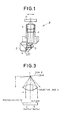
- Fig. 1 is a cross-sectional view showing an arrangement of a pickup P to be used in the optical disk player of this invention.
- this pickup P there are provided in the body 1 thereof, a laser light source 2 to emit a laser light beam, a mirror 3 for reflecting the laser light beam in the direction of the disk D, an objective lens 4 for converging the incident light beam on the information recording surface of the disk D, and a photodetector 5 for receiving reflected light beam from the disk D passing through the objective lens 4.
- the body 1 including objective lens 4 and photodetector 5 is disposed to be integrally movable in the radial direction (-) of the disk when driven by a tracking actuator (not shown). Also, the body 1 is integrally movable in the direction of optical axis by a focus actuator (not shown). Actual arrangement of such pickup P is described in detail in the specification of the Japanese Patent Application Laid Open No. 2-135726 filed by the present applicant.
- the photodetector 5 incorporated in the pickup P is, as shown in the figure, a so-called quadrant type photodetector consisting of four photoelectric conversion elements 5a - 5d, in which the light receiving surface is divided into four parts by a division line L 1 along tangential direction of the track and a division line L 2 perpendicular to it. It is arranged in such manner that the center O of the light receiving surface coincides with optical axis of reflected light beam from the disk D when tracking conditions are adequate.
- the outputs Sa and Sc of the photoelectric conversion elements 5a and 5c disposed on a diagonal line and the outputs Sb and Sd of the photoelectric conversion elements 5b and 5d are added by adders 6 and 7.
- the outputs of the photoelectric conversion elements on both sides the division line Li that is, the outputs Sa and Sd of the photoelectric conversion elements 5a and 5d and the outputs Sb and Sc of the photoelectric conversion elements 5b and 5c are added by adders 8 and 9 respectively.
- the adding outputs (Sa + Sc) and (Sb + Sd) of the adder 6 and 7 are supplied to the phase comparator 14 through BPFs (band pass filters) 10 and 11 and the limiters (LIM) 12 and 13.
- the phase comparator 14 outputs the voltage proportional to the phase difference between two inputs.
- the phase difference output of the phase comparator 14 is derived as the tracking error signal through LPF (low pass filter) 15.
- the polarity and the level of the tracking error signal indicate the deviation direction and the deviation of information reading optical spot in the radial direction of the disk relative to the recording track of the disk D.
- the tracking error signal is selectively supplied to the tracking actuator (not shown) by a loop switch 16.
- the adding outputs (Sa + Sd) and (Sb + Sc) of the adders 8 and 9 are supplied to the subtractor 17, and the difference between these two outputs is obtained.
- This difference output ⁇ (Sa + Sd) - (Sb + Sd) ⁇ is supplied to LPF 20, and its DC component is derived as disk tilt detecting signal.
- This disk tilt detecting signal indicates the inclination of the information recording surface of the disk D with respect to the optical axis of information reading optical beam. Specifically, as shown in Fig.
- the disk tilt detecting signal thus obtained is supplied to the tilt actuator (not shown) of tilt servo mechanism, which controls the optical axis of the optical beam for reading information to the direction perpendicular to the information recording surface of the disk D.
- the tile servo mechanism the one disclosed in the Japanese Provisional Utility Model Application Laid Open No. 59-168835 may be used.
- the disk tilt detection signal is used as a driving signal of the tilt motor of this tilt servo mechanism.
- an offset is generated by relative movement of objective lens 4 and photodetector 5 in the receiving light quantity of two areas divided along the direction of the recording track in addition to the offset component caused by disk tilt.
- it is not the offset caused by the tilt when tilt servo is locked. Because the objective lens 4 and photodetector 5 are integrated, the offset caused by relative movement of these two can be neglected.
- the differential output ⁇ (Sa + Sd) - (Sb + Sc) ⁇ of the subtractor is also supplied to the zero-cross detecting circuit 19, which consists of zero level comparator.
- the polarity and the level of this differential output indicates deviation direction and deviation of the information reading optical spot in radial direction of the disk in relation to the recording track of the disk D. Accordingly, it is possible according to this differential output to detect that the information reading optical spot has reached in the intermediate position on-track and off-track in the zero-cross detecting circuit 19. Therefore, if the zero-cross detecting signal, i.e. the detection output of the zero-cross detection circuit 19 is used, it is possible to detect the timing accurately and at all times to give braking power to the tracking actuator during jumping, i.e. zero-cross timing on off-track.
- the adding outputs (Sa + Sd) and (Sb + Sc) of the adders 8 and 9 are further supplied to the adder 21, and the sum of these two outputs in obtained. Then, the total output ⁇ (Sa + Sd) + (Sb + Sc) ⁇ of the photoelectric conversion elements Sa - Sd is derived as a reading RF signal.
- the photodetector may be divided by a curve provided by projecting the straight line in parallel or perpendicular to the recording track on the disk through objective lens or through optical components, which generate the astigmatism for the focussing operation.
- a quadrant type photodetector consisting of four photoelectric conversion elements with light receiving surface divided into four parts is used as means for receiving reflected light beam from the disk.
- the phase difference output obtained by the time difference detection method based on four detection outputs of this photodetector is issued as tracking error signal, and DC components of differential output obtained by the push-pull method is issued as disk tilt detection signal. Further, zero-cross of this differential output is detected, and the detection output is used for zero- cross detection on off-track. Accordingly, zero-cross time on off-track can be accurately detected even when time difference detection method is used for generating the tracking error signal.
Landscapes
- Optical Recording Or Reproduction (AREA)
Applications Claiming Priority (2)
| Application Number | Priority Date | Filing Date | Title |
|---|---|---|---|
| JP191451/90 | 1990-07-19 | ||
| JP2191451A JP2998807B2 (ja) | 1990-07-19 | 1990-07-19 | 光学式ディスクプレーヤ |
Publications (3)
| Publication Number | Publication Date |
|---|---|
| EP0467498A2 true EP0467498A2 (de) | 1992-01-22 |
| EP0467498A3 EP0467498A3 (en) | 1992-02-26 |
| EP0467498B1 EP0467498B1 (de) | 1996-05-08 |
Family
ID=16274849
Family Applications (1)
| Application Number | Title | Priority Date | Filing Date |
|---|---|---|---|
| EP91301940A Expired - Lifetime EP0467498B1 (de) | 1990-07-19 | 1991-03-08 | Optischer Plattenspieler |
Country Status (4)
| Country | Link |
|---|---|
| US (1) | US5130963A (de) |
| EP (1) | EP0467498B1 (de) |
| JP (1) | JP2998807B2 (de) |
| DE (1) | DE69119314T2 (de) |
Cited By (5)
| Publication number | Priority date | Publication date | Assignee | Title |
|---|---|---|---|---|
| EP0984436A2 (de) * | 1998-08-29 | 2000-03-08 | Samsung Electronics Co., Ltd. | Verfahren, Gerät und Platte zum Steuern von Servofehlern |
| EP1085509A2 (de) * | 1999-09-16 | 2001-03-21 | Samsung Electronics Co., Ltd. | Fehlersignalerfassungsvorrichtung und Wiedergabesignalerfassungsvorrichtung eines optischen Aufzeichnungs-/Wiedergabesystems |
| EP1207523A2 (de) * | 2000-11-17 | 2002-05-22 | Samsung Electronics Co., Ltd. | Fehlersignalerzeugungsgerät eines optischen Aufzeichnungs-/Wiedergabesystems |
| EP1553571A2 (de) * | 2004-01-08 | 2005-07-13 | Kabushiki Kaisha Toshiba | Optische Plattenvorrichtung und Verfahren zu deren Steuerung |
| EP1414028A3 (de) * | 2002-10-21 | 2006-10-25 | Pioneer Corporation | Vorrichtung und Verfahren zur Erfassung des Neigungswinkels |
Families Citing this family (19)
| Publication number | Priority date | Publication date | Assignee | Title |
|---|---|---|---|---|
| US5452276A (en) * | 1991-01-31 | 1995-09-19 | Deutsche Thomson-Brandt/Gmbh | Tracking regulation circuit including apparatus for disabling coarse drive signals |
| KR930008067B1 (ko) * | 1991-07-31 | 1993-08-25 | 삼성전자 주식회사 | 틸트센서를 이용한 디스크 센싱회로 |
| JP2630151B2 (ja) * | 1992-01-30 | 1997-07-16 | 日本ビクター株式会社 | 光ディスク装置 |
| JP3437239B2 (ja) * | 1994-02-16 | 2003-08-18 | オリンパス光学工業株式会社 | 情報再生装置 |
| JP3336778B2 (ja) * | 1994-11-25 | 2002-10-21 | 松下電器産業株式会社 | トラッキング誤差検出装置 |
| JP3478677B2 (ja) * | 1996-08-22 | 2003-12-15 | 株式会社東芝 | 光ディスク装置ならびにその制御方法 |
| US5956304A (en) * | 1997-08-15 | 1999-09-21 | Cirrus Logic, Inc. | Differential phase error detector using dual arm correlation for servo tracking in an optical disk storage device |
| JPH11213441A (ja) * | 1998-01-23 | 1999-08-06 | Rohm Co Ltd | 光ピックアップおよびその調整方法 |
| US6888951B1 (en) * | 1999-08-23 | 2005-05-03 | Nagaoka & Co., Ltd. | Methods and apparatus for analyzing operational and analyte data acquired from optical disc |
| KR100716941B1 (ko) * | 1999-10-21 | 2007-05-10 | 삼성전자주식회사 | 광디스크 기록/재생장치의 레이저 스폿 이동 방향 판단방법 및 이에 적합한 장치 |
| JP3486145B2 (ja) | 2000-01-17 | 2004-01-13 | 松下電器産業株式会社 | デジタル記録データ再生装置 |
| DE10041426A1 (de) * | 2000-08-23 | 2002-03-07 | Thomson Brandt Gmbh | Verfahren zur Spurführung in einem Gerät zum Lesen und/oder Beschreiben eines optischen Aufzeichnungsträgers sowie entsprechendes Gerät zum Lesen und/oder Beschreiben eines optischen Aufzeichnungsträgers |
| US7061594B2 (en) * | 2000-11-09 | 2006-06-13 | Burstein Technologies, Inc. | Disc drive system and methods for use with bio-discs |
| JP2002170265A (ja) * | 2000-12-01 | 2002-06-14 | Pioneer Electronic Corp | チルトサーボ制御装置及び方法 |
| WO2002056311A2 (en) * | 2001-01-11 | 2002-07-18 | Burstein Technologies Inc | Optical disc analysis system including related methods for biological and medical imaging |
| JP2002260354A (ja) * | 2001-03-02 | 2002-09-13 | Funai Electric Co Ltd | サーボ制御装置およびゲイン調整方法 |
| US7221632B2 (en) * | 2001-07-12 | 2007-05-22 | Burstein Technologies, Inc. | Optical disc system and related detecting methods for analysis of microscopic structures |
| US20080094974A1 (en) * | 2001-11-09 | 2008-04-24 | Burstein Technologies, Inc. | Optical disc system and related detecting methods for analysis of microscopic structures |
| JP2005536821A (ja) * | 2002-08-21 | 2005-12-02 | コーニンクレッカ フィリップス エレクトロニクス エヌ ヴィ | トラッキングシステム及び方法 |
Citations (5)
| Publication number | Priority date | Publication date | Assignee | Title |
|---|---|---|---|---|
| US4497048A (en) * | 1981-04-22 | 1985-01-29 | Olympus Optical Co. Ltd. | Technique for controlling tracking in an optical disc apparatus |
| EP0138277A2 (de) * | 1983-10-17 | 1985-04-24 | Koninklijke Philips Electronics N.V. | Gerät zur Wiedergabe von Informationen auf einem optisch lesbaren Informationsträger |
| EP0313818A2 (de) * | 1987-10-29 | 1989-05-03 | Pioneer Electronic Corporation | Optisches Informationswiedergabegerät |
| EP0357323A2 (de) * | 1988-09-02 | 1990-03-07 | Sharp Kabushiki Kaisha | Optische Abtastvorrichtung |
| JPH0279228A (ja) * | 1988-09-14 | 1990-03-19 | Sharp Corp | 光ピックアップ装置 |
Family Cites Families (6)
| Publication number | Priority date | Publication date | Assignee | Title |
|---|---|---|---|---|
| JPS5753830A (en) * | 1980-09-12 | 1982-03-31 | Sony Corp | Tracking servo device for optical information signal reproducer |
| JPS58125242A (ja) * | 1982-01-22 | 1983-07-26 | Victor Co Of Japan Ltd | 光学的情報信号再生装置のトラツキング誤差検出方式 |
| JPS60256927A (ja) * | 1984-06-01 | 1985-12-18 | Nippon Gakki Seizo Kk | 光学式デイスク再生装置の読取り制御装置 |
| JPH0629610B2 (ja) * | 1985-04-19 | 1994-04-20 | 株式会社日立製作所 | 磁気デイスク装置のスピンドル機構 |
| JPH067413B2 (ja) * | 1985-07-03 | 1994-01-26 | 株式会社リコー | 光ピツクアツプのトラツキング制御方式 |
| CA1261467A (en) * | 1985-11-28 | 1989-09-26 | Akira Minami | Focus servomechanism control system of optical disc system having offset setting means |
-
1990
- 1990-07-19 JP JP2191451A patent/JP2998807B2/ja not_active Expired - Fee Related
-
1991
- 1991-02-26 US US07/660,951 patent/US5130963A/en not_active Expired - Fee Related
- 1991-03-08 EP EP91301940A patent/EP0467498B1/de not_active Expired - Lifetime
- 1991-03-08 DE DE69119314T patent/DE69119314T2/de not_active Expired - Fee Related
Patent Citations (5)
| Publication number | Priority date | Publication date | Assignee | Title |
|---|---|---|---|---|
| US4497048A (en) * | 1981-04-22 | 1985-01-29 | Olympus Optical Co. Ltd. | Technique for controlling tracking in an optical disc apparatus |
| EP0138277A2 (de) * | 1983-10-17 | 1985-04-24 | Koninklijke Philips Electronics N.V. | Gerät zur Wiedergabe von Informationen auf einem optisch lesbaren Informationsträger |
| EP0313818A2 (de) * | 1987-10-29 | 1989-05-03 | Pioneer Electronic Corporation | Optisches Informationswiedergabegerät |
| EP0357323A2 (de) * | 1988-09-02 | 1990-03-07 | Sharp Kabushiki Kaisha | Optische Abtastvorrichtung |
| JPH0279228A (ja) * | 1988-09-14 | 1990-03-19 | Sharp Corp | 光ピックアップ装置 |
Cited By (18)
| Publication number | Priority date | Publication date | Assignee | Title |
|---|---|---|---|---|
| US6721243B2 (en) | 1998-08-29 | 2004-04-13 | Samsung Electronics Co., Ltd. | Method for detecting servo error, apparatus therefor, disk which maintains quality of servo error signal, method of controlling servo of disk recording/reproducing apparatus, method of detecting tracking error, and method of detecting tilt error |
| EP0984436A3 (de) * | 1998-08-29 | 2002-03-13 | Samsung Electronics Co., Ltd. | Verfahren, Gerät und Platte zum Steuern von Servofehlern |
| EP0984436A2 (de) * | 1998-08-29 | 2000-03-08 | Samsung Electronics Co., Ltd. | Verfahren, Gerät und Platte zum Steuern von Servofehlern |
| US7110334B2 (en) | 1998-08-29 | 2006-09-19 | Samsung Electronics Co., Ltd. | Method for detecting servo error, apparatus therefor, disk which maintains quality of servo error signal, method of controlling servo of disk recording/reproducing apparatus, method of detecting tracking error, and method of detecting tilt error |
| EP1293972A2 (de) * | 1998-08-29 | 2003-03-19 | Samsung Electronics Co., Ltd. | Verfahren zum Erkennen von Servofehlern, Spurfolgefehlern und Neigungsfehlern, und Gerät dazu |
| EP1293972A3 (de) * | 1998-08-29 | 2003-05-07 | Samsung Electronics Co., Ltd. | Verfahren zum Erkennen von Servofehlern, Spurfolgefehlern und Neigungsfehlern, und Gerät dazu |
| EP1308940A1 (de) * | 1998-08-29 | 2003-05-07 | Samsung Electronics Co., Ltd. | Verfahren zum Regeln des Servo-/Spurlage-/Neigungs- Fehlers eines Platten-Aufnahme-Wiedergabe-Gerät |
| EP1308941A1 (de) * | 1998-08-29 | 2003-05-07 | Samsung Electronics Co., Ltd. | Platte mit einem Spurformat zur Regelung von Servofehlern |
| US7590034B2 (en) | 1998-08-29 | 2009-09-15 | Samsung Electronics Co., Ltd. | Method for detecting servo error, apparatus therefor, disk which maintains quality of servo error signal, method of controlling servo of disk recording/reproducing apparatus, method of detecting tracking error, and method of detecting tilt error |
| US7319643B2 (en) | 1998-08-29 | 2008-01-15 | Samsung Electronics Co., Ltd. | Method for detecting servo error, apparatus therefor, disk which maintains quality of servo error signal, method of controlling servo of disk recording/reproducing apparatus, method of detecting tracking error, and method of detecting tilt error |
| US7167424B2 (en) | 1998-08-29 | 2007-01-23 | Samsung Electronics Co., Ltd. | Method for detecting servo error, apparatus therefor, disk which maintains quality of servo error signal, method of controlling servo of disk recording/reproducing apparatus, method of detecting tracking error, and method of detecting tilt error |
| EP1085509A3 (de) * | 1999-09-16 | 2007-01-31 | Samsung Electronics Co., Ltd. | Fehlersignalerfassungsvorrichtung und Wiedergabesignalerfassungsvorrichtung eines optischen Aufzeichnungs-/Wiedergabesystems |
| EP1085509A2 (de) * | 1999-09-16 | 2001-03-21 | Samsung Electronics Co., Ltd. | Fehlersignalerfassungsvorrichtung und Wiedergabesignalerfassungsvorrichtung eines optischen Aufzeichnungs-/Wiedergabesystems |
| EP1207523A2 (de) * | 2000-11-17 | 2002-05-22 | Samsung Electronics Co., Ltd. | Fehlersignalerzeugungsgerät eines optischen Aufzeichnungs-/Wiedergabesystems |
| EP1207523A3 (de) * | 2000-11-17 | 2007-06-06 | Samsung Electronics Co., Ltd. | Fehlersignalerzeugungsgerät eines optischen Aufzeichnungs-/Wiedergabesystems |
| EP1414028A3 (de) * | 2002-10-21 | 2006-10-25 | Pioneer Corporation | Vorrichtung und Verfahren zur Erfassung des Neigungswinkels |
| EP1553571A3 (de) * | 2004-01-08 | 2007-11-28 | Kabushiki Kaisha Toshiba | Optische Plattenvorrichtung und Verfahren zu deren Steuerung |
| EP1553571A2 (de) * | 2004-01-08 | 2005-07-13 | Kabushiki Kaisha Toshiba | Optische Plattenvorrichtung und Verfahren zu deren Steuerung |
Also Published As
| Publication number | Publication date |
|---|---|
| EP0467498B1 (de) | 1996-05-08 |
| EP0467498A3 (en) | 1992-02-26 |
| US5130963A (en) | 1992-07-14 |
| JP2998807B2 (ja) | 2000-01-17 |
| DE69119314T2 (de) | 1996-10-24 |
| JPH0476829A (ja) | 1992-03-11 |
| DE69119314D1 (de) | 1996-06-13 |
Similar Documents
| Publication | Publication Date | Title |
|---|---|---|
| US5130963A (en) | Optical disk player | |
| EP0468613B1 (de) | Optischer Plattenspieler | |
| US4815060A (en) | Optical pickup device with tracking and focusing utilizing a photodetector having four regions | |
| JP3455298B2 (ja) | 光ビームの移動検出方法および光ディスク再生装置 | |
| US5408452A (en) | Optical information recording/reproducing system including novel tracking system | |
| JPH01107325A (ja) | トラック調整回路 | |
| KR101053375B1 (ko) | 스큐 검출 방법 및 광 픽업과 광 디스크 장치 | |
| JPH04274032A (ja) | 光学情報記録再生装置 | |
| US6091679A (en) | Tracking error signal generating method and apparatus | |
| JP4001196B2 (ja) | 情報記録装置及び情報再生装置 | |
| KR100312803B1 (ko) | 광헤드장치 | |
| JPH11250475A (ja) | 光ディスク装置 | |
| JP2912981B2 (ja) | 光学情報記録再生装置 | |
| JPH02152024A (ja) | 分離型光ピックアップ装置における光軸ずれ補正方法 | |
| JPH11102526A (ja) | 光学ヘッドおよび光学的情報再生装置 | |
| KR100293522B1 (ko) | 광픽업장치 | |
| JPH08279163A (ja) | 光ディスク装置およびシーク方法 | |
| KR100717856B1 (ko) | 부빔의 각도 조정이 필요없는 광 디스크 장치의 광 픽업 | |
| KR100200856B1 (ko) | 광픽업의 구동 알고리즘 | |
| JPH04274033A (ja) | 光学情報記録再生装置 | |
| JPH09330522A (ja) | 光ディスク装置 | |
| JPH04251442A (ja) | トラッキングエラー検出装置 | |
| JPH08306055A (ja) | 光ディスク装置 | |
| JP2005222646A (ja) | 光ヘッド装置及び光ディスク装置 | |
| JPH08235605A (ja) | 光デイスク装置 |
Legal Events
| Date | Code | Title | Description |
|---|---|---|---|
| PUAI | Public reference made under article 153(3) epc to a published international application that has entered the european phase |
Free format text: ORIGINAL CODE: 0009012 |
|
| PUAL | Search report despatched |
Free format text: ORIGINAL CODE: 0009013 |
|
| AK | Designated contracting states |
Kind code of ref document: A2 Designated state(s): DE FR GB |
|
| AK | Designated contracting states |
Kind code of ref document: A3 Designated state(s): DE FR GB |
|
| 17P | Request for examination filed |
Effective date: 19920226 |
|
| 17Q | First examination report despatched |
Effective date: 19940928 |
|
| GRAH | Despatch of communication of intention to grant a patent |
Free format text: ORIGINAL CODE: EPIDOS IGRA |
|
| GRAA | (expected) grant |
Free format text: ORIGINAL CODE: 0009210 |
|
| AK | Designated contracting states |
Kind code of ref document: B1 Designated state(s): DE FR GB |
|
| REF | Corresponds to: |
Ref document number: 69119314 Country of ref document: DE Date of ref document: 19960613 |
|
| ET | Fr: translation filed | ||
| PLBE | No opposition filed within time limit |
Free format text: ORIGINAL CODE: 0009261 |
|
| STAA | Information on the status of an ep patent application or granted ep patent |
Free format text: STATUS: NO OPPOSITION FILED WITHIN TIME LIMIT |
|
| 26N | No opposition filed | ||
| REG | Reference to a national code |
Ref country code: GB Ref legal event code: 746 Effective date: 19980115 |
|
| REG | Reference to a national code |
Ref country code: FR Ref legal event code: D6 |
|
| PGFP | Annual fee paid to national office [announced via postgrant information from national office to epo] |
Ref country code: FR Payment date: 19990309 Year of fee payment: 9 |
|
| PGFP | Annual fee paid to national office [announced via postgrant information from national office to epo] |
Ref country code: GB Payment date: 19990311 Year of fee payment: 9 |
|
| PGFP | Annual fee paid to national office [announced via postgrant information from national office to epo] |
Ref country code: DE Payment date: 19990315 Year of fee payment: 9 |
|
| PG25 | Lapsed in a contracting state [announced via postgrant information from national office to epo] |
Ref country code: GB Free format text: LAPSE BECAUSE OF NON-PAYMENT OF DUE FEES Effective date: 20000308 |
|
| GBPC | Gb: european patent ceased through non-payment of renewal fee |
Effective date: 20000308 |
|
| PG25 | Lapsed in a contracting state [announced via postgrant information from national office to epo] |
Ref country code: FR Free format text: LAPSE BECAUSE OF NON-PAYMENT OF DUE FEES Effective date: 20001130 |
|
| REG | Reference to a national code |
Ref country code: FR Ref legal event code: ST |
|
| PG25 | Lapsed in a contracting state [announced via postgrant information from national office to epo] |
Ref country code: DE Free format text: LAPSE BECAUSE OF NON-PAYMENT OF DUE FEES Effective date: 20010103 |