EP0455113A2 - Auf Fe basierende weichmagnetische Legierung, und diese Legierung enthaltendes Magnetmaterial und magnetischer Apparat, der diese Materialien verwendet - Google Patents
Auf Fe basierende weichmagnetische Legierung, und diese Legierung enthaltendes Magnetmaterial und magnetischer Apparat, der diese Materialien verwendet Download PDFInfo
- Publication number
- EP0455113A2 EP0455113A2 EP91106549A EP91106549A EP0455113A2 EP 0455113 A2 EP0455113 A2 EP 0455113A2 EP 91106549 A EP91106549 A EP 91106549A EP 91106549 A EP91106549 A EP 91106549A EP 0455113 A2 EP0455113 A2 EP 0455113A2
- Authority
- EP
- European Patent Office
- Prior art keywords
- atomic
- alloy
- cooling roll
- soft magnetic
- based soft
- Prior art date
- Legal status (The legal status is an assumption and is not a legal conclusion. Google has not performed a legal analysis and makes no representation as to the accuracy of the status listed.)
- Granted
Links
Images


Classifications
-
- H—ELECTRICITY
- H01—ELECTRIC ELEMENTS
- H01F—MAGNETS; INDUCTANCES; TRANSFORMERS; SELECTION OF MATERIALS FOR THEIR MAGNETIC PROPERTIES
- H01F41/00—Apparatus or processes specially adapted for manufacturing or assembling magnets, inductances or transformers; Apparatus or processes specially adapted for manufacturing materials characterised by their magnetic properties
- H01F41/02—Apparatus or processes specially adapted for manufacturing or assembling magnets, inductances or transformers; Apparatus or processes specially adapted for manufacturing materials characterised by their magnetic properties for manufacturing cores, coils, or magnets
- H01F41/0206—Manufacturing of magnetic cores by mechanical means
- H01F41/0213—Manufacturing of magnetic circuits made from strip(s) or ribbon(s)
- H01F41/0226—Manufacturing of magnetic circuits made from strip(s) or ribbon(s) from amorphous ribbons
-
- H—ELECTRICITY
- H01—ELECTRIC ELEMENTS
- H01F—MAGNETS; INDUCTANCES; TRANSFORMERS; SELECTION OF MATERIALS FOR THEIR MAGNETIC PROPERTIES
- H01F1/00—Magnets or magnetic bodies characterised by the magnetic materials therefor; Selection of materials for their magnetic properties
- H01F1/01—Magnets or magnetic bodies characterised by the magnetic materials therefor; Selection of materials for their magnetic properties of inorganic materials
- H01F1/03—Magnets or magnetic bodies characterised by the magnetic materials therefor; Selection of materials for their magnetic properties of inorganic materials characterised by their coercivity
- H01F1/12—Magnets or magnetic bodies characterised by the magnetic materials therefor; Selection of materials for their magnetic properties of inorganic materials characterised by their coercivity of soft-magnetic materials
- H01F1/14—Magnets or magnetic bodies characterised by the magnetic materials therefor; Selection of materials for their magnetic properties of inorganic materials characterised by their coercivity of soft-magnetic materials metals or alloys
-
- G—PHYSICS
- G11—INFORMATION STORAGE
- G11B—INFORMATION STORAGE BASED ON RELATIVE MOVEMENT BETWEEN RECORD CARRIER AND TRANSDUCER
- G11B5/00—Recording by magnetisation or demagnetisation of a record carrier; Reproducing by magnetic means; Record carriers therefor
- G11B5/127—Structure or manufacture of heads, e.g. inductive
- G11B5/147—Structure or manufacture of heads, e.g. inductive with cores being composed of metal sheets, i.e. laminated cores with cores composed of isolated magnetic layers, e.g. sheets
-
- H—ELECTRICITY
- H01—ELECTRIC ELEMENTS
- H01F—MAGNETS; INDUCTANCES; TRANSFORMERS; SELECTION OF MATERIALS FOR THEIR MAGNETIC PROPERTIES
- H01F1/00—Magnets or magnetic bodies characterised by the magnetic materials therefor; Selection of materials for their magnetic properties
- H01F1/01—Magnets or magnetic bodies characterised by the magnetic materials therefor; Selection of materials for their magnetic properties of inorganic materials
- H01F1/03—Magnets or magnetic bodies characterised by the magnetic materials therefor; Selection of materials for their magnetic properties of inorganic materials characterised by their coercivity
- H01F1/12—Magnets or magnetic bodies characterised by the magnetic materials therefor; Selection of materials for their magnetic properties of inorganic materials characterised by their coercivity of soft-magnetic materials
- H01F1/14—Magnets or magnetic bodies characterised by the magnetic materials therefor; Selection of materials for their magnetic properties of inorganic materials characterised by their coercivity of soft-magnetic materials metals or alloys
- H01F1/147—Alloys characterised by their composition
- H01F1/153—Amorphous metallic alloys, e.g. glassy metals
- H01F1/15308—Amorphous metallic alloys, e.g. glassy metals based on Fe/Ni
-
- H—ELECTRICITY
- H01—ELECTRIC ELEMENTS
- H01F—MAGNETS; INDUCTANCES; TRANSFORMERS; SELECTION OF MATERIALS FOR THEIR MAGNETIC PROPERTIES
- H01F1/00—Magnets or magnetic bodies characterised by the magnetic materials therefor; Selection of materials for their magnetic properties
- H01F1/01—Magnets or magnetic bodies characterised by the magnetic materials therefor; Selection of materials for their magnetic properties of inorganic materials
- H01F1/03—Magnets or magnetic bodies characterised by the magnetic materials therefor; Selection of materials for their magnetic properties of inorganic materials characterised by their coercivity
- H01F1/12—Magnets or magnetic bodies characterised by the magnetic materials therefor; Selection of materials for their magnetic properties of inorganic materials characterised by their coercivity of soft-magnetic materials
- H01F1/14—Magnets or magnetic bodies characterised by the magnetic materials therefor; Selection of materials for their magnetic properties of inorganic materials characterised by their coercivity of soft-magnetic materials metals or alloys
- H01F1/147—Alloys characterised by their composition
- H01F1/153—Amorphous metallic alloys, e.g. glassy metals
- H01F1/15341—Preparation processes therefor
-
- H—ELECTRICITY
- H01—ELECTRIC ELEMENTS
- H01F—MAGNETS; INDUCTANCES; TRANSFORMERS; SELECTION OF MATERIALS FOR THEIR MAGNETIC PROPERTIES
- H01F1/00—Magnets or magnetic bodies characterised by the magnetic materials therefor; Selection of materials for their magnetic properties
- H01F1/01—Magnets or magnetic bodies characterised by the magnetic materials therefor; Selection of materials for their magnetic properties of inorganic materials
- H01F1/03—Magnets or magnetic bodies characterised by the magnetic materials therefor; Selection of materials for their magnetic properties of inorganic materials characterised by their coercivity
- H01F1/12—Magnets or magnetic bodies characterised by the magnetic materials therefor; Selection of materials for their magnetic properties of inorganic materials characterised by their coercivity of soft-magnetic materials
- H01F1/14—Magnets or magnetic bodies characterised by the magnetic materials therefor; Selection of materials for their magnetic properties of inorganic materials characterised by their coercivity of soft-magnetic materials metals or alloys
- H01F1/147—Alloys characterised by their composition
- H01F1/153—Amorphous metallic alloys, e.g. glassy metals
- H01F1/15358—Making agglomerates therefrom, e.g. by pressing
-
- H—ELECTRICITY
- H01—ELECTRIC ELEMENTS
- H01F—MAGNETS; INDUCTANCES; TRANSFORMERS; SELECTION OF MATERIALS FOR THEIR MAGNETIC PROPERTIES
- H01F10/00—Thin magnetic films, e.g. of one-domain structure
- H01F10/08—Thin magnetic films, e.g. of one-domain structure characterised by magnetic layers
- H01F10/10—Thin magnetic films, e.g. of one-domain structure characterised by magnetic layers characterised by the composition
- H01F10/12—Thin magnetic films, e.g. of one-domain structure characterised by magnetic layers characterised by the composition being metals or alloys
- H01F10/13—Amorphous metallic alloys, e.g. glassy metals
- H01F10/131—Amorphous metallic alloys, e.g. glassy metals containing iron or nickel
-
- H—ELECTRICITY
- H01—ELECTRIC ELEMENTS
- H01F—MAGNETS; INDUCTANCES; TRANSFORMERS; SELECTION OF MATERIALS FOR THEIR MAGNETIC PROPERTIES
- H01F10/00—Thin magnetic films, e.g. of one-domain structure
- H01F10/08—Thin magnetic films, e.g. of one-domain structure characterised by magnetic layers
- H01F10/10—Thin magnetic films, e.g. of one-domain structure characterised by magnetic layers characterised by the composition
- H01F10/12—Thin magnetic films, e.g. of one-domain structure characterised by magnetic layers characterised by the composition being metals or alloys
- H01F10/13—Amorphous metallic alloys, e.g. glassy metals
- H01F10/133—Amorphous metallic alloys, e.g. glassy metals containing rare earth metals
- H01F10/135—Amorphous metallic alloys, e.g. glassy metals containing rare earth metals containing transition metals
- H01F10/136—Amorphous metallic alloys, e.g. glassy metals containing rare earth metals containing transition metals containing iron
Definitions
- the present invention relates to an Fe based soft magnetic alloy. Further, the present invention relates to magnetic materials containing such a soft magnetic alloy, for example, ribbons, compressed powders and the like as well as to a process and apparatus for producing such magnetic materials. Also, the present invention relates to magnetic transducers such as a magnetic head, a transformer and a choke coil. However, the present invention is also useful in other applications.
- Soft magnetic alloys used in magnetic heads, transformers choke coils and the like must generally have the following characteristics:
- magnetic heads must have the following characteristics in addition to (1) to (4) above from a point of view of abrasion resistance:
- crystalline alloys such as Sendust, Permalloy (50 % Ni-Fe Permalloy, 80 % Ni-Fe Permalloy, etc.), and silicon steel (see for example, Japanese Patent Publication Nos. 37688/1987 and 45285/1987).
- Fe-based or Co-based amorphous alloys have also been used.
- the aforementioned Sendust has a defect that its saturated magnetic flux density is as low as about 11 kG while it has an excellent soft magnetic characteristics.
- Permalloy has a defect that it has a low saturated magnetic flux density as low as about 8 kG when it has an alloy composition which exhibits an excellent soft magnetic characteristics. More particularly, when it is applied to magnetic cores, core loss at high frequencies is large and the temperature of the core increases drastically at a frequency of no less than several tens kHz, resulting in that it is difficult to use as a material for magnetic cores.
- Silicon steel has a high saturated magnetic flux density but it has a poor soft magnetic characteristics. Also it is disadvantageous in that its iron loss is not low enough and thus it is unsatisfactory from a point of view of energy saving or a problem of heat generation when used in transformers.
- Co-based amorphous magnetic cores have been increasingly used as cores for controlling switching power source, making the most of their features of having a low core loss at high frequencies and having a high squareness.
- the Co-based amorphous alloys have problems that not only they are costly because raw materials thereof are expensive but also they have a low saturated magnetic flux density at a frequency in a zone of several tens kHz to 100 kHz and therefore they suffer from limited working magnetic flux density, thus making it difficult to sufficiently miniaturize magnetic cores.
- Fe-Based alloys generally have a high saturated magnetic flux density and those having a saturated magnetic flux density as high as 15 kG or higher can be obtained but they have an insufficient soft magnetic characteristics. It is known that Fe-based amorphous alloys give rise to magnetic cores having a high squareness ratio of a direct current B-H curve and a high maximum permeability can be obtained as described in Japanese Patent Publication No. 1183/1983.
- Fe-based amorphous alloys have a large iron loss and efforts have been made to improve the iron loss by adjusting additive elements but in spite thereof Fe-based amorphous alloys still have a large iron loss as compared with Co-based amorphous alloys.
- Fe-based amorphous alloys have an extremely large magnetic strain and is sensitive to stress. Therefore, they have a problem that their magnetic characteristics tend to be deteriorated due to deformations as a result of mechanical vibration or by the weight of the alloys themselves.
- FIG. 1 shows a conventional apparatus for continuously producing a ribbon made of an amorphous alloy according to a so-called single roll method.
- the apparatus has a cooling roll 1 made of Cu which is rotated at a high speed and a nozzle 2 arranged in the vicinity of a top portion of the roll 1 which sprays a molten metal 3 onto the roll 1 to thereby quickly cooling the molten metal 3 on the surface of the cooling roll 1 and solidify it so that a ribbon can be formed, which ribbon is drawn in a direction in which the cooling roll 1 rotates.
- the surface of the cooling roll 1 is mirror surface-finished
- the nozzle 2 is provided substantially vertically at a top portion of the cooling roll 1, with the distance between the tip of the nozzle and the surface of the cooling roll 1 being set to about 1 mm or less.
- the molten metal 3 discharged from the nozzle 2 forms a puddle 4 which is substantially standstill between the tip of the nozzle 2 and the surface of the cooling roll 1.
- the cooling roll 1 rotates, the molten metal 3 is drawn out from the puddle 4 and cooled on the surface of the cooling roll 1 to be solidified in the form of a belt or ribbon, thus continuously forming a ribbon 5.
- soft magnetic alloys generally used as a material for making magnetic heads is required to have a sufficiently smooth surface, that is, their surface roughness must be sufficiently small.
- ribbons produced by the conventional apparatus fail to always have a surface roughness small enough to be useful for acoustic magnetic heads and accordingly it has been strenuously demanded to develop an apparatus for producing an alloy ribbon which can give rise to smooth surface.
- ribbons produced thereby have a surface roughness which fluctuates between the both surfaces. More specifically, in comparison with the roll contacting surface, which is formed while the molten metal is being solidified in contact with the cooling roll, the free solidification surface, which is formed by solidification of the molten metal without contact with the roll, has a relatively large surface roughness. Because of this defect, it is difficult to use the ribbons as a material for making magnetic heads.
- the present invention is intended to provide Fe-based soft magnetic alloys free of the above-described problems, magnetic materials containing such alloys, a process and apparatus for producing the magnetic materials, as well as magnetic transducers using the magnetic materials.
- An object of the present invention is to provide a soft magnetic alloy having a high saturated magnetic flux density and a high permeability and at the same time having a high mechanical strength and a high thermal stability.
- Another object of the present invention is to provide a process for heat treatment of an Fe-based soft magnetic alloy in order to improve the magnetic characteristics thereof.
- Still another object of the present invention is to provide a soft magnetic thin film having a high saturated magnetic flux density and a high permeability and at the same time having a high mechanical strength and a high thermal stability.
- Yet another object of the present invention is to provide a process and apparatus for producing an Fe-based soft magnetic alloy ribbon having a high saturated magnetic flux density and a high permeability and at the same time having a high mechanical strength and a high thermal stability with its physical-chemical properties such as surface roughness or extent of oxidation being improved.
- an object of the present invention is to provide a magnetic transducers, such as a magnetic core, a magnetic head or a low frequency transformer, to which is applied an Fe-based soft magnetic alloy having a high saturated magnetic flux density and a high permeability and at the same time having a high mechanical strength and a high thermal stability as well as showing a small iron loss.
- a magnetic transducers such as a magnetic core, a magnetic head or a low frequency transformer
- an Fe-based soft magnetic alloy having a high saturated magnetic flux density and having a composition represented by formula (I) below: (Fe 1-a Q a ) b B x T y T' z (I) wherein Q represents at least one element selected from the group consisting of Co and Ni; T represents at least one element selected from the group consisting of Ti, Zr, Hf, V, Nb, Ta, Mo and W, with Zr and/or Hf being always included; T' represents at least one element selected from the group consisting of Cu, Ag, Au, Ni, Pd and Pt; a, b, x, y and z are real numbers satisfying relationships below: 0 ⁇ a ⁇ 0.05 atomic %, 0 ⁇ b ⁇ 93 atomic %, 0.5 ⁇ x ⁇ 16 atomic %, 4 ⁇ y ⁇ 10 atomic %, 0 ⁇ z ⁇ 4.5 atomic % provided that when 0 ⁇ a 0.05 atomic %, 0
- a process for heat treating a high magnetic flux density alloy comprising the steps of: heating an Fe-based soft magnetic alloy having a high saturated magnetic flux density and having a composition represented by formula (I) as defined above at a temperature no lower than a crystallization temperature, and cooling the alloy at a cooling rate of no lower than 100°C/minute.
- a soft magnetic thin film composed of an Fe-based soft magnetic alloy having a high saturated magnetic flux density and having a composition represented by formula (I) as defined above.
- an Fe-based soft magnetic powder compact comprising powder of an Fe-based soft magnetic alloy having a high saturated magnetic flux density and having a composition represented by formula (I) as defined above, the powder being compressed.
- a process for preparing an Fe-based soft magnetic alloy powder having a high saturated magnetic flux density comprising the steps of: heating an Fe-based soft magnetic alloy having a high saturated magnetic flux density and having a composition represented by formula (I) as defined above at a temperature no lower than a crystallization temperature to render it brittle, and pulverizing the alloy.
- an apparatus for producing an Fe-based soft magnetic alloy ribbon having a cooling roll for cooling a molten metal of an Fe-based soft magnetic alloy, the cooling roll being rotatable and a nozzle having a tip, the nozzle being associated with the cooling roll with the tip thereof being arranged in the vicinity of a surface of the cooling roll at a predetermined distance therefrom and being adapted to spray the molten metal onto the surface of the cooling roll while the cooling roll is rotated in a predetermined direction so that the molten metal on the surface of the cooling roll can be molded in the form of a ribbon while it is being cooled and withdrawn in the direction in which the cooling roll is rotated, wherein the cooling roll has an outer peripheral surface portion and an inner portion, at least one of the outer peripheral surface portion and the inner portion being made of an Fe-based alloy, and wherein the nozzle is arranged in a slanted state with its axis being slanted at a predetermined angle with respect to an imaginary vertical
- an apparatus for producing an Fe-based soft magnetic alloy ribbon having a cooling roll for cooling a molten metal of an Fe-based soft magnetic alloy ribbon, the cooling roll being rotatable and a nozzle having a tip, the nozzle being associated with the cooling roll with the tip thereof being arranged in the vicinity of a surface of the cooling roll at a predetermined distance therefrom and being adapted to spray the molten metal onto the surface of the cooling roll while the cooling roll is rotated in a predetermined direction so that the molten metal on the surface of the cooling roll can be molded in the form of a ribbon while it is being cooled and withdrawn in the direction in which the cooling roll is rotated, wherein the cooling roll has an outer peripheral surface portion and an inner portion, at least one of the outer peripheral portion and the inner portion being made of an Fe-based alloy, and wherein the outer peripheral surface portion has a surface roughness corresponding to that obtainable by polishing with a polishing paper having a grain number of 100 to 1,000.
- an Fe-based soft magnetic alloy ribbon by providing a molten metal of an Fe-based soft magnetic alloy, ejecting the alloy through a nozzle onto a surface of a cooling roll being rotated in a predetermined direction, the nozzle being associated with the cooling roll with a tip of the nozzle being arranged in the vicinity of the surface of the cooling roll at a predetermined distance therefrom, and withdrawing the ribbon in the same direction as that in which the cooling roll is rotated, wherein the cooling roll has an outer peripheral portion and an inner portion, at least one of the outer peripheral portion and the inner portion being made of an Fe-based alloy, and wherein the nozzle is arranged in a slanted state with its axis being slanted at a predetermined angle with respect to an imaginary vertical axis in the same direction as the direction in which the cooling roll is rotated.so that the molten metal from the tip of the nozzle can be ejected onto the surface of the cooling roll which
- an Fe-based soft magnetic alloy ribbon by providing a molten metal of an Fe-based soft magnetic alloy, ejecting the alloy through a nozzle onto a surface of a cooling roll being rotated in a predetermined direction, the nozzle being associated with the cooling roll with a tip of the nozzle being arranged in the vicinity of the surface of the cooling roll at a predetermined distance therefrom, and withdrawing the ribbon in the same direction as that in which the cooling roll is rotated, wherein the cooling roll has an outer peripheral portion and an inner portion, at least one of the outer peripheral portion and the inner portion being made of an Fe-based alloy, and wherein the outer peripheral surface portion has a surface roughness corresponding to that obtainable by polishing with a polishing paper having a grain number of 100 to 1,000.
- a process for producing an Fe-based soft magnetic alloy ribbon comprising the steps of: providing a molten metal of an Fe-based soft magnetic alloy having a composition represented by formula (I) as defined above, providing an evacuatable chamber, housing a nozzle for ejecting the molten metal and a cooling roll in the evacuatable chamber, establishing vacuum in the evacuatable chamber, ejecting the alloy through the nozzle onto a surface of the cooling roll while the roll is being rotated in a predetermined direction, the nozzle being associated with the cooling roll with a tip of the nozzle being arranged in the vicinity of the surface of the cooling roll at a predetermined distance therefrom, to form a ribbon of the alloy, and withdrawing the ribbon in the same direction as that in which the cooling roll is rotated.
- a magnetic core made of an Fe-based soft magnetic alloy, wherein said Fe-based soft magnetic alloy is composed of a high saturated magnetic flux density Fe-based soft magnetic alloy having having a composition represented by formula (I) as defined above.
- a low frequency transformer having an Fe-based soft magnetic alloy and a conductor wire, wherein said Fe-based soft magnetic alloy is composed of a high saturated magnetic flux density Fe-based soft magnetic alloy having a composition represented by formula (I) as defined above.
- a magnetic head having a core made of an Fe-based soft magnetic alloy, wherein said Fe-based soft magnetic alloy is composed of a high saturated magnetic flux density Fe-based soft magnetic alloy having a composition represented by formula (I) as defined above.
- an Fe-based soft magnetic alloy not only having soft magnetic characteristics equal to or superior to the conventional alloys put into practical use but also having a higher saturated magnetic flux density.
- the soft magnetic alloy of the invention has a high mechanical strength and a high thermal stability simultaneously.
- the Fe-based soft magnetic alloy of he invention is suitable for magnetic transducers such as transformers and choke coils of which further reduction in size is demanded, and when it is used in these applications it can effectively increase performance of the magnetic transducers and reduce their size and weight.
- ribbons made of Fe-based soft magnetic alloys can be produced continuously in a state in which their physical chemical properties such as surface roughness or extent of oxidation is improved.
- the Fe-based soft magnetic alloy represented by formula (I) according to the present invention includes the following species.
- the high saturated magnetic flux density Fe-based soft magnetic alloy of the present invention can usually be prepared by a method including the steps of preparing, by quenching of a molten metal or by a gas phase quenching, an amorphous alloy having the above-described composition (composition (I), or composition (Ia), (Ib), (Ic) or (Id)) or a crystalline alloy containing such an amorphous alloy phase, and a heat treating the resulting alloy to deposit fine crystal grains.
- the alloy in order to make it easy to obtain an amorphous phase, the alloy must contain either one of Zr and Hf which have a high amorphous phase forming capability.
- a portion of Zr or Hf may be replaced by one or more of Ti, V, Nb, Ta, Mo and W selected from among elements belonging to the group 4A to 6A of the periodic table. These elements are sometimes referred to herein as the first additive elements.
- the reason why Cr is not included in the first additive elements is that Cr has a poorer capability of forming an amorphous phase than the other elements recited above. However, once a suitable amount of Zr and/or Hf is present in the alloy, Cr may be added too.
- B boron
- B has an effect of increasing the capability of the alloy of the present invention to form an amorphous phase and an effect of inhibiting formation of a phase of a compound which affects adversely on the magnetic characteristics in the above-described heat treatment step.
- addition of B is essential.
- Other elements such as Al, Si, C and P are commonly used together with B as an amorphous phase forming element.
- the alloy of the present invention may contain such amorphous phase forming elements.
- the alloy when the content of B and one or more of the first additive elements is relative high (i.e, x is more than 8 atomic %; and y is more than 9 atomic %), the alloy must contain at least one element selected from among Cu, Ni and those elements which are in the same family as Cu and Ni as the second additive element in an amount of 4.5 atomic % or less, preferably no less than 0.2 atomic % and no more than 4.5 atomic %. If the content of the second additive element or elements is less than 0.2 atomic %, excellent soft magnetic characteristics cannot be obtained during the above-described heat treatment. However, this is not a fatal defect because in this case, desirable soft magnetic characteristics can be obtained by increasing the cooling rate to some extent.
- the second additive elements particularly preferred is Cu.
- the amounts of the elements contained in the Fe-based soft magnetic alloy of the present invention are limited to specified ranges.
- elements belonging to the platinum family such as Cr and Ru may be added in order to improve corrosion resistance of the alloy.
- Y, rare earth elements, Zn, Cd, Ga, In, Ge, Sn, Pb, As, Sb, Bi, Se, Te, Li, Be, Mg, Ca, Sr, Ba and the like may also be added in order to adjust magnetic strain of the alloy.
- Inevitable impurities such as H, N, O and S may be present in the Fe-based soft magnetic alloy of the present invention in amounts such that desired characteristics of the alloy are not deteriorated.
- the alloy composition containing the inevitable impurities in such amounts may be deemed to be the same as or equivalent to the composition of the high saturated magnetic flux density Fe-based soft magnetic alloy of the invention.
- the content of B in the alloy of the invention is within the range of 0.5 ⁇ x ⁇ 16 atomic % in the case where the second additive element or elements are present or within the range of 0.5 ⁇ x ⁇ 8 atomic % in the case where no second additive element is present that it becomes easy to obtain an effective permeability of 10,000 or higher.
- the content of the first additive element or elements in the alloy of the invention in the case where the second additive element or elements are contained in the alloy, the effective permeability of no lower than 10,000 is not obtained with less than 4 atomic % of the first additive element while with above 10 atomic % of the first additive element not only the permeability decreases drastically but also saturated magnetic flux density decreases considerably. Therefore, the content of the first additive element is limited within the range of 4 ⁇ y ⁇ 10 atomic %. In the case where the second additive element is absent, the content of the first additive element or elements is similarly limited within the range of 4 ⁇ y ⁇ 9 atomic %.
- the content b of Fe + Co and/or Ni as main components of the alloy of the present invention is no more than 92 atomic % in the case where one or more of the second elements are present, or no more than 93 atomic % in the case where the second element is absent.
- a high permeability is not obtained if it exceeds 92 atomic % in the presence of the second additive element(s) or 93 atomic % in the absence of the second additive element.
- b be no less than 75 atomic %.
- the soft magnetic alloy composition is heated at a temperature higher than its crystallization temperature, preferably at a temperature of 550 to 650°C, and subsequently cooled at a cooling rate of 100°C/minute or higher.
- the cooling rate of lower than 100°C/minute is undesirable because the resulting soft magnetic alloy has a decreased permeability.
- the magnetic characteristics of the alloy of the present invention can be controlled by properly selecting optimal heat treatment conditions. Also, it is possible to improve the magnetic characteristics by annealing the alloy in a magnetic field.
- the Fe-based soft magnetic alloy of the present invention can be obtained usually in the form of a ribbon by a quenching method, and the ribbon is used for producing a magnetic core for magnetic heads after punching and laminating it.
- the ribbon is used for producing a magnetic core for magnetic heads after punching and laminating it.
- powder of the amorphous alloy is prepared and compressed together with a binder to form a powder compact serving as a magnetic head or choke coil having a desired shape.
- the alloy of the present invention has excellent magnetic characteristics even when it is in the form of a thin film, it is useful as a soft magnetic thin film which can be used as a core for magnetic heads.
- the method of forming a thin film of the Fe-based soft magnetic alloy of the invention described above there can be used various methods utilizing an apparatus for forming a thin film such as a sputtering apparatus and a vapor deposition apparatus.
- the sputtering apparatus there can be used any known ones, for example, RF two-layer sputter, DC sputter, magnetron sputter, 3-electrode sputter, ion beam sputter, confronting target type sputter and the like.
- the thin film thus-prepared is subjected to heat treatment in which the film is heated to form fine crystal grains.
- This heat treatment step is the same as used for the above-described Fe-based soft magnetic alloy itself.
- a single roll type apparatus As an apparatus for continuously producing ribbon of an amorphous alloy, there is known a single roll type apparatus as shown in Fig. 1.
- the apparatus shown in Fig. 1 is operates as follows. That is, while the cooling roll 1 made of Cu is being rotated at a high speed, the molten metal 3 is ejected from the nozzle 2 arranged in the vicinity of the top of the roll. Thus, the molten metal 3 is quenched on the surface of the cooling roll 1 to be solidified and molded into a ribbon, which is then withdrawn in the same direction as the direction in which the cooling roll 1 rotates.
- the Surface of the cooling roll 1 is mirror surface-finished and the nozzle 2 is provided substantially vertically at the top of the roll, with the distance between the tip of the nozzle and the surface of the cooling roll at the top thereof is set to about 1 mm or less.
- the molten metal 3 discharged from the nozzle 2 forms a puddle 4 which is substantially at a standstill and repose between the tip of the nozzle 2 and the surface of the cooling roll 1.
- the cooling roll 1 rotates, the molten metal is withdrawn from the puddle 4 and cooled on the surface of the roll in the form of a ribbon 5, thus producing the ribbon 5 continuously.
- the surface of the cooling roll is made rougher than the mirror surface-finished surface to increase friction between the ribbon and the surface of the roll greater than ever, thereby preventing slipping of the ribbon on the cooling roll and thus preventing the occurrence of unevenness in the freely solidified surface.
- This improves the surface roughness condition of the freely solidified surface.
- the surface roughness of the cooling roll contacting surface depends on the surface roughness of the surface of the cooling roll, the surface roughness values of the both surfaces of the ribbon can be made substantially equal by optimally adjusting the surface roughness of the surface of the cooling roll. As a result, Fe-based soft magnetic ribbons suitable for magnetic heads and the like can be obtained.
- molten metal of the soft magnetic alloy having the specified composition gives rise to ribbons of Fe-based soft magnetic alloy which have a high saturated magnetic flux density and a high permeability as well as having a high hardness and an excellent thermal resistance and which are suitable for magnetic heads and the like.
- Fig. 2 shows the apparatus for continuously producing a ribbon according to the above-described embodiment of the present invention.
- the apparatus shown in Fig. 2 has substantially the same construction as the conventional apparatus shown in Fig. 1, and similarly operates. That is, a cooling roll 10 is rotated at a high speed, and while it is being rotated, a molten metal 30 is ejected onto the roll from a nozzle 20 arranged in the vicinity of the top of the cooling roll 10 to thereby quench and solidify the molten metal.30 to form a ribbon 50, which is then withdrawn in the same direction as the direction in which the cooling roll 10 is rotated.
- the cooling roll 10 is made of an Fe-based alloy. That is, the cooling roll 10 is constructed by an Fe-based alloy such as stainless steel. It should be appreciated that only outer peripheral surface portion of the cooling roll may be made of the Fe-based alloy.
- the outer peripheral surface portion of the cooling roll 10 is finished to have a surface roughness larger than mirror surface-finished one by being polished with a polishing paper having a grain number 600 to 1,000, preferably 800. By so doing, the surface roughness values on the both sides of the ribbon 50 are made substantially uniform therebetween.
- the surface roughness values of the both sides of the ribbon can be made sufficiently small and uniform therebetween by making the surface of the cooling roll 10, or at least outer peripheral surface portion of the cooling roll 10, to have a surface roughness corresponding to that obtainable by polishing with a polishing paper having a grain number of 600 to 1,000, preferably 800. Therefore, the apparatus according to the instant embodiment of the present invention is suitable as an apparatus for continuously producing a soft magnetic alloy ribbon useful as a material for magnetic heads, particularly acoustic magnetic heads.
- molten metal 30 As for the molten metal 30, a molten metal of the Fe-based soft magnetic alloy having a composition represented by formula (I) as defined above.
- the molten metal of the alloy having the above-described composition When a molten metal of the alloy having the above-described composition is ejected from the nozzle 20 onto the top of the cooling roll 10 while the roll is being rotated, the molten metal of the alloy forms the puddle 40 on the top of the cooling roll 10 and extruded therefrom along the surface of the cooling roll to produce the ribbon 50.
- the ribbon 50 is mostly composed of an amorphous phase.
- the outer peripheral surface portion of the cooling roll 10 is made of an Fe-based alloy, which is excellent in its wettability with the Fe-based soft magnetic alloy, thus facilitating separation of the ribbon 50 from the cooling roll 10 so that the ribbon 50 obtained has a uniform thickness.
- the cooling roll 10 made of a metal other than the Fe-based alloy e.g., a roll made of Cu or the like, because in this case the molten metal is scattered when it is ejected from the nozzle 20 to fail to produce ribbons of a good shape.
- the surface of the cooling roll 10 is formed to have a suitable roughness, the ribbon 50 is prevented from slipping on the cooling roll 10, resulting in that the ribbon 50 has a sufficiently small surface roughness on the both sides.
- Annealing of the ribbon 50 thus obtained by heating at a temperature of 500 to 620°C followed by gradual cooling leads to crystallization of non-uniform amorphous phase in the ribbon 50, and as result there are formed a number of regions where local crystallization is ready to occur, thus forming non-uniform nuclei.
- a Fe-based soft magnetic alloy ribbon having a high saturated magnetic flux density and a high permeability as well as exhibiting excellent soft magnetic characteristics and being very hard and excellent in thermal resistance can be obtained.
- the surface roughness values of the both sides of the ribbon can be made sufficiently small and uniform therebetween by making the surface of the cooling roll 10, or at least outer peripheral surface portion of the cooling roll 10, to have a surface roughness corresponding to that obtainable by polishing with a polishing paper having a grain number of 600 to 1,000, preferably 800. Therefore, the apparatus according to the instant embodiment of the present invention is suitable as an apparatus for continuously producing a soft magnetic alloy ribbon useful as a material for magnetic heads, particularly acoustic magnetic heads.
- the tip of the nozzle is arranged so as to confront the surface of the roll in a slanted state such that the tip is directed toward backward side with respect to direction of rotation of the cooling roll.
- the size or volume of the puddle formed between the tip of the nozzle and the cooling roll is larger than that formed in the conventional apparatus.
- molten metal of the soft magnetic alloy having the specified composition gives rise to an Fe-based soft magnetic ribbon having a high saturated magnetic flux density and a high permeability as well as being very hard and excellent in thermal stability and thus are suitable for magnetic heads.
- Figs. 3 and 4 shows the construction of the apparatus for producing a ribbon according to still another embodiment of the present invention.
- the apparatus according to the instant embodiment can be constructed with the same or similar members as used in the apparatus shown in Fig. 2 but is different from the apparatus shown in Fig. 2 in the direction of the nozzle and the direction of rotation of the cooling roll. Roughening of the cooling roll is not essential but it is preferred to carry out the roughening.
- the direction of rotation of the cooling roll 10 is contrary to that of the cooling roll in the apparatus shown in Fig. 2, and the resulting ribbon 50 is withdrawn to the left as indicated by an arrow in Fig. 3.
- the molten metal 30 is supplied vertically downward from the nozzle 20 arranged vertically so that the tip of the nozzle is directed in a direction passing the center in vertical cross section of the cooling roll 10 and therefore there is no difference regardless of the direction of rotation of the cooling roll 10.
- the direction of rotation of the cooling roll is fixed for the direction of slanting of the nozzle (explained hereinbelow).
- nozzle 20 is arranged in the vicinity of the top of the cooling roll 10, with the tip of the nozzle being directed toward backward side with respect to the direction of rotation of the cooling roll (right hand side in Fig. 3) at a predetermined angle with respect to an imaginary vertical axis.
- the angle ⁇ of slanting of the nozzle with respect to imaginary vertical axis is set to a value within the range of not exceeding 40°.
- molten metal 30 to be sprayed to the cooling roll 10 there can be used a molten metal of the Fe-based soft magnetic alloy having a composition represented by formula (I) as defined above.
- the molten metal of the alloy having the above-described composition When a molten metal of the alloy having the above-described composition is ejected from the nozzle 20 onto the top of the cooling roll 10 while the roll is being rotated in the direction indicated by an arrow A in Fig. 3, the molten metal of the alloy forms the puddle 40 on the top of the cooling roll 10 and is extruded therefrom along the surface of the cooling roll to produce the ribbon 50.
- the ribbon 50 is mostly composed of an amorphous phase.
- the outer peripheral surface portion of the cooling roll 10 is made of an Fe-based alloy, which is excellent in its wettability with the Fe-based soft magnetic alloy, so that the ribbon 50 can be conveyed smoothly out of the cooling roll 10.
- the cooling roll 10 made of a metal other than the Fe-based alloy e.g., a roll made of Cu or the like, because in this case the molten metal is scattered when it is ejected from the nozzle 20 to fail to produce ribbons of a good shape.
- the ribbon 50 is withdrawn from this large puddle.stably. the larger the puddle 40 the less the variation in the size of the puddle 40, thus giving rise to the ribbon 50 having a uniform thickness.
- Annealing of the ribbon 50 thus obtained by heating at a temperature of 500 to 620°C followed by gradual cooling leads to crystallization of non-uniform amorphous phase in the ribbon 50, and as result there are formed a number of regions where local crystallization is ready to occur, thus forming non-uniform nuclei.
- a Fe-based soft magnetic alloy ribbon having a high saturated magnetic flux density and a high permeability as well as exhibiting excellent soft magnetic characteristics and being very hard and excellent in thermal resistance can be obtained.
- Fig. 5 is a graph plotting results of actual measurement, showing the relationship between the angle ⁇ of slanting of the nozzle 20 and surface roughness Rz of the cooling roll.
- Horizontal axis indicates the angle ⁇ of slanting of the nozzle 20 while the vertical axis indicates ratio Rz/Rz0 where Rz0 is the surface roughness at an angle ⁇ being 0° and Rz is the surface roughness with the slanted nozzle 20 being slanted at an angle ⁇ being larger than 0°.
- the surface roughness Rz becomes smaller, that is, the surface of the resulting ribbon becomes smoother with increase of the angle ⁇ of slanting of the nozzle 20.
- surface roughness values Rz0 and Rz are obtained by calculation from 10 point average roughness prescribed in JIS-B-0601 metered using a needle type surface roughness meter.
- the reason why the surface roughness Rz reduces by slanting the nozzle 20 is presumably ascribable to increase of the size of the puddle 40 formed between the tip of the nozzle 20 and the cooling roll 10 when the nozzle is slanted as compared with the case where the nozzle 20 is not slanted, which reduces substantially subtle variation in the volume of the puddle 40 according as the molten metal 30 is withdrawn from the puddle 40, thus assuring that the molten metal is withdrawn stably from the puddle.
- the puddle 40 grows larger according as the angle ⁇ of slanting of the nozzle 20 increases to a certain level.
- the angle ⁇ exceeds 40°, the molten metal 30 flows down on the backward side with respect to the direction of rotation of the cooling roll 10 due to the weight of itself, thus failing to form the puddle 40. Therefore, the angle ⁇ does not have to exceed 40°.
- the nozzle is slanted such that the tip thereof is directed toward forward side with respect to the direction of rotation of the cooling roll 10, the puddle 40 of a large side is not formed and therefore no improvement in the surface roughness of the resulting ribbon can be obtained.
- Fig. 6 is a graph plotting results of examination on the influence of the distance between the tip of the nozzle 20 and the surface of the cooling roll 10 when the angle ⁇ of slanting of the nozzle 20 is fixed.
- the horizontal axis indicates the gap or distance between the tip of the nozzle 20 and the surface of the cooling roll 10 (size l 1 described above) while the vertical axis indicates the surface roughness Rz and Rmax of the ribbon 50 formed.
- Rmax is maximum surface roughness measured using a needle type surface roughness meter. From the graph shown in Fig. 6, it can be seen that Rz and Rmax are the smallest when size l 1 is set to a value within the range of 0.3 to 0.5 mm.
- l 1 it is preferred to set the value of l 1 within that range.
- ⁇ 40°
- the nozzle and the cooling roll are housed in a chamber evacuated to vacuum and in this state the molten metal is sprayed onto the cooling roll to form a ribbon. Therefore, a ribbon of a non-oxidized alloy containing less impurities.
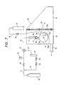
- Fig. 7 shows an example of the apparatus used in the practice of the process of the invention.
- the apparatus shown in Fig. 7 is basically constructed by a chamber 60 in which the cooling roll 10 and a crucible 11 are housed.
- the chamber 60 has a box-like body 12, which houses therein the cooling roll 10 and the crucible 11, and a box-like housing 13 connected to the body 12.
- the body 12 and the housing 13 are bolted together through flange portions 12a and 13a, respectively, so that the connected portion is of an airtight structure.
- a exhaust piping 14, which is connected to an evacuating apparatus, is connected to the body 12 of the chamber 60,
- the cooling roll 10 is supported by a rotary shaft 10a penetrating side walls of the chamber 60.
- the cooling roll 10 is driven to rotate by a motor (not shown) provided outside the chamber 60 through the rotary shaft 10a.
- the portions of side walls at which the rotary shaft 10a penetrates therethrough are provided with a magnetic seal and rendered airtight.
- the nozzle 20 On the lower end of the crucible 11 is provided the nozzle 20.
- a heating coil 11 is provided on the lower part of the crucible 11. Inside the crucible 11 is housed the molten metal 30 of an Fe-soft magnetic alloy.
- the upper part of the crucible 11 is connected to a gas source 18 for supplying a gas such as Ar gas through a supply piping or connecting pipe 15, which has incorporated therein a pressure control valve 19 and a magnetic valve 21.
- a pressure gage 22 In the midway of the supply piping 15 between the pressure control valve and the magnetic valve 21 is provided a pressure gage 22.
- An auxiliary piping 23 is connected to the piping 15 in parallel therewith The auxiliary piping 23 has incorporated therein a pressure control valve 24, a flow rate control valve 25 and a flowmeter 26. That is, a gas such as Ar can be supplied from the gas source 18 to the inside of the crucible 11 so that the molten metal can be sprayed onto the cooling roll 10 from the nozzle 20.
- a gas source 31 for supplying a gas such as Ar gas through a connecting pipe 32, which has incorporated therein a pressure control valve 33 so that Ar gas or the like can be sent to the inside of the chamber 60.
- the cooling roll 10 and the nozzle 20 in the apparatus shown in Fig. 7 are substantially of the same construction as those in the conventional apparatus shown in Fig. 1. That is, the cooling roll 10 is rotated at a high speed, and while it is being rotated, the molten metal 30 is blown onto the roll from a nozzle 20 arranged in the vicinity of the top of the cooling roll 10 to thereby quench and solidify the molten metal.30 in the form of a ribbon, which is then withdrawn in the same direction as the direction in which the cooling roll 10 is rotated.
- the cooling roll 10 is made of an Fe-based alloy. That is, the cooling roll 10 is constructed by an Fe-based alloy such as stainless steel. It should be noted that only outer peripheral surface portion of the cooling roll 10 may be made of the Fe-based alloy.
- the outer peripheral surface portion of the cooling roll 10 is finished to have a surface roughness larger than mirror surface-finished one by being polished with a polishing paper having a grain number 600 to 1,000, preferably 800.
- a polishing paper having a grain number 600 to 1,000, preferably 800.
- the surface roughness values of the both sides of the ribbon can be made sufficiently small and uniform therebetween by making the surface of the cooling roll 10, or at least outer peripheral surface portion of the cooling roll 10, to have a surface roughness corresponding to that obtainable by polishing with a polishing paper having a grain number of 600 to 1,000, preferably 800. Therefore, the apparatus according to the instant embodiment of the present invention is suitable as an apparatus for continuously producing a soft magnetic alloy ribbon useful as a material for magnetic heads, particularly acoustic magnetic heads.
- molten metal 30 As for the molten metal 30, a molten metal of the Fe-based soft magnetic alloy having a composition represented by formula (I) as defined above.
- the inside of he chamber 60 is evacuated and then a non-oxidative gas such as Ar gas is sent to the chamber 60 thus evacuated from the gas source 31.
- Ar gas is pressed into the inside of the crucible 11 to thereby eject the molten metal 30 from the nozzle 20, and at the same time the cooling roll 10 is rotated at a high speed in the direction indicated by an arrow A in Fig. 7.
- the molten metal 30 is extruded along the surface of the cooling roll 10 while forming the puddle 40 on the top of the cooling roll 10 to form the ribbon 50.
- the ribbon 50 is mostly composed of an amorphous phase.
- the outer peripheral surface portion of the cooling roll 10 is made of an Fe-based alloy, which is excellent in its wettability with the Fe-based soft magnetic alloy, thus facilitating separation of the ribbon 50 from the cooling roll 10 so that the ribbon 50 obtained has a uniform thickness.
- the cooling roll 10 made of a metal other than the Fe-based alloy e.g., a roll made of Cu or the like, because in this case the molten metal is scattered when it is ejected from the nozzle 20 to fail to produce ribbons of a good shape.
- the surface of the cooling roll 10 is formed to have a suitable roughness, the ribbon 50 is prevented from slipping on the cooling roll 10, resulting in that the ribbon 50 has a sufficiently small surface roughness on the both sides.
- the molten metal 30 being quenched is not oxidized nor the ribbon 50 withdrawn from the cooling roll 10 after quenching is oxidized.
- the ribbon 50 withdrawn from the cooling roll 10 is stored in the housing 13 in the chamber 60. Because the ribbon 50 is in a preheated state and still at a high temperature, it otherwise tends to be oxidized upon exposure to the air but the inside of the chamber 60 is filled with Ar gas, which prevents oxidation in the chamber 60 from occurring.
- Annealing of the ribbon 50 thus obtained by heating at a temperature of 500 to 620°C followed by gradual cooling leads to crystallization of non-uniform amorphous phase in the ribbon 50, and as result there are formed a number of regions where local crystallization is ready to occur, thus forming non-uniform nuclei.
- a Fe-based soft magnetic alloy ribbon having a high saturated magnetic flux density and a high permeability as well as exhibiting excellent soft magnetic characteristics and being very hard and excellent in thermal resistance can be obtained.
- the apparatus used may be that shown in Fig. 7 but uses the same slanted nozzle as shown in Figs. 3 and 4.
- the nozzle 20 is slanted on the side which cause no obstacle in withdrawing the resulting ribbon 50.
- the surface roughness values of the both sides of the ribbon can be made sufficiently small and uniform therebetween by making the surface of the cooling roll 10, or at least outer peripheral surface portion of the cooling roll 10, to have a surface roughness corresponding to that obtainable by polishing with a polishing paper having a grain number of 600 to 1,000, preferably 800. Therefore, the apparatus according to the instant embodiment of the present invention is suitable as an apparatus for continuously producing a soft magnetic alloy ribbon useful as a material for magnetic heads, particularly acoustic magnetic heads.
- soft magnetic alloy powder having the specified composition makes it possible to obtain a powder compact made of a soft magnetic alloy powder being compressed and having a high saturated magnetic flux density and a high permeability as well as having a high mechanical strength and a high thermal stability.
- Powder of the high saturated magnetic flux density Fe-based soft magnetic alloy according to the present invention can be prepared usually by a process including a step of quenching a molten metal of a soft magnetic alloy having a composition represented by formula (I) as defined above by an atomizing method or the like to convert it into powder, and a step of heating the powder obtained in the preceding step to deposit fine crystal grains.
- the powder can also be prepared by preparing an alloy having a composition represented by formula (I) as defined above, heating the alloy at a temperature no lower than the crystallization temperature thereof to render it brittle, and then pulverizing it.
- the alloy material having the above-described composition is molten in a crucible using a high frequency still and the molten metal is flown down through a nozzle for ejecting the molten metal provided on the bottom of the crucible, with blowing nitrogen gas at a predetermined pressure through a multi-hole atomizing nozzle arranged, for example, in a circle, to the molten metal flow dropping from the nozzle for ejecting the molten metal.
- investigation made by the present inventors has revealed that the above-described soft magnetic alloy having the specified composition becomes brittle upon heating, and therefore the alloy can be powdered utilizing this property.
- powder can be obtained by heating the alloy having the aforementioned composition at a temperature no lower than the crystallization temperature thereof, preferably 550 to 650°C, to render it brittle and pulverizing it in this state to adjust its particle diameter.
- the above-described alloy is transformed into an amorphous phase texture in a quenched state and therefore is rich in ductility so that it is difficult to pulverize as it is in order to obtain its powder. Accordingly, the alloy obtained as above is heated at a temperature of 500°C or higher to embrittle it and pulverized in this state using a grinder such as a roll mill or an attritor. As a result of this operation, a soft magnetic alloy powder having a particle diameter of about 1 to about 100 ⁇ m can be obtained.
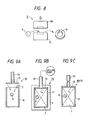
- a soft magnetic alloy powder A is molded into a core B having a predetermined shape using a top force PU and a bottom tool PL of a press P.
- the molded core B is then inserted and sealed in a pressurizing capsule 70 shown.
- Figs. 9A, 9B and 9C together with a pressure medium powder C.
- Figs. 9A to9C only one molded core B is illustrated but in practice a plurality of molded cores B are inserted and sealed in the pressurizing capsule 70.
- the pressurizing capsule 70 has a cylindrical body 71 with a bottom and a detachable cover or lid 72 on the body 71.
- a deaering pipe 73 has an opening in the cover 72.
- the pressurizing capsule 70 are introduced the molded core B and the pressure medium powder C in a state in which the cover is detached.
- a mesh plate 74 which does not allow passage of the molded core B and the pressure medium powder C therethrough is placed on the inner surface of the body 71 on the upper part thereof, followed by welding the body 71 and the cover 71 to seal gaps therebetween.
- the deaering pipe 73 is collapsed to be discommunicated with the outside, thus completing a sealed work 90 (pressurizing capsule 70) in which the molded core B and the pressure medium powder C are included.
- the pressuring capsule 70 Upon deaering, the pressuring capsule 70 is introduced in a heating furnace F and heated at a temperature of about 500 to 900°C. This heat treatment is intended to more completely effect degasification as commonly carried out for this kind of deaeration.
- the pressure medium powder C is selected from materials which do not undergo chemical reaction with the soft magnetic alloy powder A (molded core B).
- the molded core B is made of the Fe-based soft magnetic alloy powder having the aforementioned composition, favorable results are obtained when ZrO2 powder is used as the pressure medium powder C.
- MgO powder may also be used.
- Fig. 10 is a schematic cross-sectional view of a hydraulic hot press 80, in which a high pressure cylinder 81 is closable at both upper and lower ends with an upper lid 82 and a lower lid 83, respectively.
- a high pressure gas conduit 84 has an opening in the upper lid 82.
- a stand 85 for supporting the work 90 and a heater 86 and an insulation layer 87 is provided between the high pressure cylinder 81 and the heater 86.
- the work 90 is mounted on the stand 85 and heated by the heater 86 to a high temperature, and at the same time is applied an isotropic pressure by means of a high pressure gas as a pressure medium introduced therein through the conduit 84.
- the work 90 (capsule 70) is deformed wholly by compression.
- the molded core B in the capsule 70 is exposed to isotropic pressure through the pressure medium powder C.
- it receives the heat from the heater 86 through the pressure medium powder C. From this it follows that no abrupt heating of the molded core B occurs and hence no crack nor deformation due to abrupt heating does occur in the molded core B.
- the molded core B is uniformly or isotropically compressed with bubbles inside being removed and then finally sintered to complete a magnetic head core D.
- the magnetic head core D thus obtained shrinks more than the molded core B and hence the shape of the molded core B is determined taking into consideration the amount of such shrinkage.
- the work 90 compression deformed as described above is taken out from the hot hydraulic press, and thereafter the body 71 and the lid 72 are broken as shown in Fig. 11 for taking out the complete magnetic head core D inside the work 90. Because the magnetic head core D is processed in advance so as to have a predetermined shape, it can be used as it is without further processing as a magnetic head core.
- the molded core B is covered entirely with the pressure medium powder C which does not undergo chemical reaction with the core B, and therefore there is no fear that the complete magnetic head core D suffer from change in the properties.
- annular magnetic core D as shown in Fig. 12 and a drum type magnetic core D1 as shown in Fig. 13
- the process of the invention can be applied to production of various types of magnetic cores such as magnetic cores for antennae in the form of a rod or plate, multi-hole type magnetic cores, screw type magnetic cores, cup type magnetic cores, pot type magnetic cores or magnetic cores of other shapes.
- transformers can be produced.
- Fig. 14 shows the transformer according to one embodiment of the present invention.
- Transformer T includes a pair of magnetic cores 100 and 100 and a wiring 101 wound around the magnetic cores 100 and 100 main elements.
- the magnetic core 100 is formed by winding a ribbon of the alloy several times to form a laminate.
- the ribbon is formed of a soft magnetic alloy ribbon and an insulating layer of MgO or the like formed on one surface of the ribbon.
- the soft magnetic alloy constituting the above-described ribbon, there can be used a high saturated magnetic flux density Fe-based soft magnetic alloy having a composition represented by formula (I) as defined above.
- the alloy mostly has a saturated magnetic flux density of usually 10 kG or higher.
- a ribbon having a width of about several tens millimeters (mm) and a thickness of 20 to 40 ⁇ m can be obtained.
- an insulating layer of MgO or the like is formed on the ribbon by a conventional method such as electrophoresis, metallizing, sputtering or vapor deposition. By winding the ribbon with the insulating layer inside, the magnetic core 100 as shown in Fig. 15 can be obtained.
- the magnetic core 100 is retained at a temperature of 500 to 700°C for 1 hour and quenched by water quenching or the like technique to quench it, followed by annealing, to crystallize the Fe-based soft magnetic alloy constituting the magnetic core 100. This crystallization improves the magnetic characteristics and thermal resistance of the magnetic core, thus giving the objective magnetic core 100.
- the low frequency transformer which is constructed by an Fe-based soft magnetic alloy having a high saturated magnetic flux density and a high permeability, exhibits excellent magnetic characteristics, and at the same time, the alloy itself has been heat treated at a temperature of no lower than 500°C, naturally it has an excellent thermal resistance.
- transformers suitable for transformers for power distribution used at commercial frequencies or inverter transformers used at low frequencies can be obtained. Therefore, according to the present invention, there can be obtained transformers suitable for transformers for power distribution used at commercial frequencies or inverter transformers used at low frequencies
- a magnetic head can be produced which has a laminate type core to which is applied a ribbon made of the Fe-based soft magnetic alloy according to the present invention.
- the magnetic head 100 with a laminate type core has a pair of symmetrically split holding cases 111 and 111 for fixing various elements to respective predetermined positions.
- Each of the holding cases 111 and 111 has a slidable contact surface 111a which is arcuate on one side thereof so that it can achieve a smooth sliding action facing a magnetic tape.
- the laminate type core 112 is made of a plurality of pieces of sheet of a magnetic material in the form of a substantially U-shaped core leaf 113 laminated one on another.
- a pair of such laminate type cores 112 and 112 are butted to each other and the butting surface is defined as a magnetic gap 114.
- a coil 115 is wound around the laminate type core 112 and a gap plate 116 is placed as interrupting the magnetic gap 114 being inserted therein as shown in Fig. 16 to basically construct the magnetic head 110.
- the laminate type core 112 includes a plurality of core leaves 113 punched out from the alloy ribbon and laminated one on another.
- Leaves of the Fe-based soft magnetic alloy of the present invention having a suitable thickness, e.g., 30 mm, are subjected to pressing and barrel polishing to prepare core leaves 113.
- the leaves themselves are annealed (600°C) in the step of annealing.
- the annealed core leaves 113 are inserted in a jig and arranged in the same direction in an array in the step of aligning the core leaves 113 to be caused to adhere closely to each other, and at the same time, for every predetermined number of the core leaves 113 a partition is inserted.
- the core leaves 113 and the partitions are welded in the direction of lamination by laser welding in a state where the core leaves 113 and the partitions are caused to adhere closely to each other.
- the core leaves are separated.
- the core leaves are laminated as a laminate with a predetermined number of core leaves.
- the laminates thus obtained are then dipped in an a resin solution in a resin impregnation step t form an insulating resin film between the respective core leaves 113, thus giving the laminate type core 112 as shown in Fig. 17A.
- Magnetic heads having more complicated shapes may be constructed as magnetic heads having a powder compact type core prepared by compacting powder of the Fe-based soft magnetic alloy according to the present invention.
- Fig. 18 shows a magnetic head 120 according to an embodiment of the present invention.
- the magnetic head 120 is used mainly for tape recorders, and is constructed by a magnetic head core D around which a coil 121 is wound around and a holder 122 holding the magnetic head core D.
- a bobbin 123 is provided on each end of the coil 121.
- the magnetic head core is formed with a gap 124.
- the magnetic head core is produced by compacting the Fe-based soft magnetic alloy powder having a composition represented by formula (I) as defined above in the same manner as the production process of the powder compact described above.
- Fig. 19 shows the magnetic head according to another embodiment of the present invention.
- the magnetic head 130 is also used mainly for tape recorders.
- the soft magnetic alloy powder of the present invention is compacted in the same manner as the powder compact described above to form a magnetic head core D, around which is provided a holder 131 to complete basic construction of the magnetic head 130.
- a magnetic head core D around which is provided a holder 131 to complete basic construction of the magnetic head 130.
- two gaps 132 In the surface of the magnetic head core D facing a magnetic recording medium are formed two gaps 132.
- Fig. 20 shows a magnetic head according to still another embodiment of the present invention.
- a magnetic head 140 is used mainly for VTR.
- the soft magnetic alloy powder of the present invention is compacted in the same manner as the production process of the powder compact described above to prepare a core half D1 of a U-shaped structure and a plate-like core half D2. These core halves are coupled on a coupling surface 141 to form a magnetic head core D and a gap 142 as well as a groove 143 for wiring.
- the magnetic head 140 is basically constructed by winding a coil 144 around the groove 143 in the magnetic head core D.
- Alloys of Examples 1 to 8 hereinbelow were prepared by a single roll liquid quenching method. That is, a molten metal was ejected from a nozzle positioned above a single steel roll rotating in a predetermined direction under pressure applied by means of argon gas onto the surface of the cooling roll.to quench it to obtain a ribbon.
- the ribbon thus produced was about 15 mm in width and about 20 to 40 ⁇ m.
- Permeability was measured by an inductance method, which was carried out using a solenoid prepared by processing the ribbon into a ring having an outer diameter of 10 mm and an inner diameter of 5 mm, superimposing a plurality of such rings to form a laminate, around which was wound a coil.
- Measurement of effective permeability ( ⁇ e) was conducted under the conditions of 10 mOe and 1 kHz.
- Coercive force (Hc) was measured using a direct current B-H loop tracer.
- Saturated magnetic flux density (Bs) was calculated from magnetization measured using a VSM at 10 kOe. Unless otherwise indicated specifically, magnetic characteristics referred to in Examples 1 to 8 below were on the material quenched in water after retaining at a temperature of 500 to 700°C for 1 hour
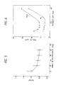
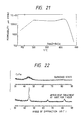
- Fig. 21 is a graph showing effects of annealing (quenching in water after retaining at a predetermined temperature for 1 hour) on the effective permeability of the Fe86Zr7B6Cu1 alloy.
- the effective permeability of the alloy of the invention in a quenched state is at a low level as low as that of of an Fe-based amorphous alloy but reaches a high value by about 10 times as high as the value obtained in the quenched state by effecting annealing at 500 to 620°C.
- the permeability was 32,000 at 1 kHz, 25,600 at 10 kHz and 8,330 at 100 kHz, indicating that even at high frequencies tested, excellent soft magnetic characteristics were obtained.
- the magnetic characteristic of the alloy of the present invention can be controlled by properly selecting conditions of heat treatment so that they can be optimized, and the magnetic characteristics can also be improved by annealing in a magnetic field.
- a halo diffractive pattern characteristic to amorphous structure was obtained in a quenched state and a diffractive pattern characteristic to body centered cubic crystals was observed after the heat treatment.
- Fig. 23 indicates that the texture after the heat treatment is composed of fine crystal grains having a particle diameter of about 100 ⁇ .
- examination on changes in hardness of the Fe86Zr7B6Cu1 alloy by heat treatment revealed that Vickers hardness of the alloy increased from 740 DPN in a quenched state to 1,390 DPN, which was much higher than was attained by the conventional material, after heat treatment at 650°C for 1 hour. This indicates that the alloy of the invention is suitable as a material for magnetic heads.
- Fig. 24 indicates that a high permeability can readily be obtained when the amount of Zr is within the range of 4 to 10 atomic % in the presence of Cu as the second additive element. With the amount of Zr being 4 atomic % or less, an effective permeability of 10,000 or higher is not obtained. The amount of Zr exceeding 10 atomic % is undesirable because not only the permeability decreases abruptly but also the saturated magnetic flux density also decreases.
- a high effective permeability as high as no lower than 10,000 can readily be obtained with the amount of B being within the range of 0.5 to 16 atomic %. Even when the amounts of Zr and of B are within the above range, no high permeability is obtained if the amount of Fe exceeds 92 atomic
- Table 2 shows magnetic characteristics of various Fe-Hf-B-Cu type alloys in which the amounts of B and of Cu were fixed to 6 atomic % and 1 atomic %, respectively.
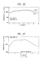
- Fig. 25 shows permeability when the amount of Hf was varied within the range of 4 to 10 atomic %. Fig. 25 also shows the effective permeability of each Fe-Zr-B6-Cu1 type alloy for comparison.
- the effective permeability of the Fe-Hf-B-C type alloys is equal to that of the Fe-Zr-B-Cu type alloys when the amount of Hf is within the range of 4 to 10 atomic %.
- the magnetic characteristics of the Fe86Zr4ZHf3B6Cu1 are equivalent to those of the Fe-Zr-B-Cu type alloys in Example 1. Therefore, Zr in the Fe-Zr-B-Cu type alloys in Example 1 can be replaced by Hf partly or entirely over the whole composition limitation range of 4 to 10 atomic %.
- Table 3 shows results of replacement of a part of Zr in the Fe-Zr-B-Cu type alloys by 1 to 5 atomic % of Nb.
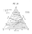
- Fig. 26 shows magnetic characteristics of the Fe-Zr-Nb-B-Cu type alloys containing 3 atomic % of Nb.
- the amount of Zr + Nb which gives a high permeability is within the range of 4 to 10 atomic % as in the case of the amount of Nb in the Fe-Zr-B-Cu type alloys. In this range, high effective permeabilities as high as the Fe-Zr-B-Cu type alloys are obtained. Therefore, a part of Zr and/or Hf in the Fe-(Zr,Hf)-B-Cu alloys can be replaced by Nb.
- Nb in the Fe-(Zr,Hf)-Mb-B-Cu type alloys can be replaced by Ti, V, Ta, Mo or W.
- Fig. 27 shows the relationship between the Cu content (z) in Fe87Zr4Nb3B6Cu x alloys and their permeability.
- Table 5 shows that each alloy exhibited effective permeability of 10,000 or higher and as excellent magnetic characteristics as alloys containing Cu. Therefore, it is clear that Cu in the alloys of the invention can be replaced by Ag, Ni, Pd or Pt.
- Fig. 28 shows the relationship between the Co content (a) in (Fe 1-a Co a )86Zr4Nb3B6Cu1 alloys and their permeability
- Thin film was prepared by a high frequency sputtering method in an Ar atmosphere. The thickness of the resulting film was 1 to 2 ⁇ m. After heat treating it at 500 to 700°C, the film was measured for its magnetic characteristics. Table 6 shows the results obtained.
- Alloys of Examples 9 to 13 hereinbelow were prepared by a single roll liquid quenching method. That is, a molten metal was ejected from a nozzle positioned above a single steel roll rotating in a predetermined direction under pressure applied by means of argon gas onto the surface of the cooling roll.to quench it to obtain a ribbon.
- the ribbon thus produced was about 15 mm in width and about 20 to 40 ⁇ m.
- Permeability was measured by an inductance method, which was carried out using a solenoid prepared by processing the ribbon into a ring having an outer diameter of 10 mm and an inner diameter of 6 mm, superimposing a plurality of such rings to form a laminate, around which was wound a coil.
- Measurement of effective permeability ( ⁇ e) was conducted under the conditions of 10 mOe and 1 kHz.
- Saturated magnetic flux density (Bs) was calculated from magnetization measured using a VSM at 10 kOe. Unless otherwise indicated specifically, magnetic characteristics referred to in Examples 9 to 13 below were on the material quenched in water after retaining at a temperature of 600°C or 650°C for 1 hour.
- Fig. 29 is a graph showing effects of annealing (quenching in water after retaining at a predetermined temperature for 1 hour) on the effective permeability of the Fe91Zr7B2 alloy.
- the effective permeability of the alloy of the invention in a quenched state is at a low level as low as that of of an Fe-based amorphous alloy but reaches a high value by about 10 times as high as the value obtained in the quenched state by effecting annealing at 500 to 650°C.
- the permeability was 26,500 at 1 kHz, 19,800 at 10 kHz and 7,80 at 100 kHz, indicating that even at high frequencies tested, excellent soft magnetic characteristics were obtained.
- Figs. 30, 31 and 32 indicate that a high permeability can readily be obtained when the amount of Zr is within the range of 4 to 9 atomic % in the absence of the second additive element. With the amount of Zr being 4 atomic % or less, an effective permeability of 10,000 or higher is not obtained. The amount of Zr exceeding 9 atomic % is undesirable because not only the permeability decreases abruptly but also the saturated magnetic flux density also decreases.
- a high effective permeability as high as no lower than 10,000 can readily be obtained with the amount of B being within the range of 0.5 to 8 atomic %. Even when the amounts of Zr and of B are within the above range, no high permeability is obtained if the amount of Fe exceeds 93 atomic %.
- Table 8 shows magnetic characteristics of various Fe-Hf-B type alloys in which the amount of Hf was varied within the range of 4 to 9 atomic %.
- Table 9 shows results of replacement of a part of Zr in the Fe-Zr-B-Cu type alloys by 1 to 5 atomic % of Nb.
- the amount of Zr + Nb which gives a high permeability is within the range of 4 to 9 atomic % as in the case of the amount of Nb in the Fe-Zr-B type alloys. In this range, high effective permeabilities as high as the Fe-Zr-B type alloys are obtained. Therefore, a part of Zr and/or Hf in the Fe-(Zr,Hf)-B alloys can be replaced by Nb.
- Nb in the Fe-(Zr,Hf)-Mb-B type alloys can be replaced by Ti, V, Ta, Mo or W.
- Fig. 34 shows the relationship between the Co + Ni content (a) in (Fe 1-a Q a )91Zr7B2 alloys and their permeability
- a soft magnetic alloy sample having a composition of Fe88Cu1B3Zr8 and the one having a composition of Fe91Zr7B2 were measured on their permeability after heating at 650°C for 1 hour and then cooling at various cooling rates.
- Fig. 35 shows the results obtained.
- a soft magnetic thin film having a composition of Fe86Zr7B6Cu1 was prepared using an RF double focus sputtering apparatus. Sputtering was performed in Ar gas atmosphere or Ar + N2 gas atmosphere using a complex target which included an Fe target and respective pellets of Zr, B and Cu properly arranged on the Fe target to form a soft magnetic thin film having a thickness of 2 ⁇ m.
- the soft magnetic thin film thus obtained was measured on its saturated magnetic flux density (Bs), initial permeability ( ⁇ , 10 mOe, 1 MHz) and coercive force (Hc) after annealing.
- the measurement of permeability and coercive force was carried out in a direction of axis of easy magnetization.
- the crystallization initiation temperature of the Fe86Zr7B6Cu1 alloy measured by differential thermal analysis conducted at a temperature elevation rate of 10°C/min. was 503°C.
- the structure of the alloy of the invention changed from amorphous structure to body centered cubic crystals, and that the texture after the heat treatment is composed of fine crystal grains having a particle diameter of about 100 ⁇ .
- a magnetic head core was prepared by the process earlier described with respect to the production of the powder compact referring to Figs. 8 to 11, and the magnetic performance of the magnetic head core obtained was measured.
- the Fe-based soft magnetic alloy powder As for the Fe-based soft magnetic alloy powder, a powder was used which was obtained by heating an alloy having a composition of F90Zr7B2Cu1 at the crystallization temperature or higher and pulverizing it.
- the soft magnetic alloy powder was molded by a press into a compact having a shape of a magnetic head core. Then, the molded article was pre-sintered at a temperature of 500 to 600°C in an inert gas atmosphere including vacuum. Subsequently, the molded article was subjected to hot hydraulic pressing under the conditions of a temperature of 600°C, a pressure of 5,000 atm, and a sintering time of 1 hour.
- the magnetic head core thus obtained had a permeability ⁇ e (1 kHz) of 18,000, a coercive force of 0.03 Oe, and a saturated magnetic flux density of 16.7 kG, and exhibited excellent magnetic characteristics.
- Fig. 36 is a graph showing the relationship between the surface roughness of the cooling roll 10 and the respective surface roughness of the ribbon 50 on each side.
- horizontal axis indicates the grain number of polishing paper used in polishing the cooling roll
- vertical axis indicates maximum surface roughness, Rmax, measured using a needle type surface roughness meter
- 10-point average surface roughness, Rz prescribed by JIS-B-0601.
- a molten metal of an Fe-based soft magnetic alloy having a composition of Fe91Zr7B2 was used.
- the surface roughness of the cooling roll-contacting surface of the ribbon does not vary so largely but roughly speaking, there was observed a tendency that the smaller the surface roughness of the cooling roll (the larger the grain number of polishing paper) the better the surface roughness of the cooling roll-contact surface of the ribbon.
- the surface roughness values on the both sides of the ribbon were substantially equal to each other, and in that case, the surface roughness of the ribbon is substantially the same as that of the cooling roll-contacting surface when the surface of the cooling roll was mirror surface-finished. (conventional case).
- polishing papers with a grain number 600 to 1,000 were used substantially the same results as above were obtained. However, outside this range, the surface roughness of the freely solidifying surface becomes too large to limit fluctuation in surface roughness within acceptable ranges.
- the Fe-based soft magnetic alloy ribbon thus obtained had a saturated magnetic flux density of 1.7 kG and a permeability at 1 kHz of 14,000, and was excellent in soft magnetic characteristics.
- the Fe-baed soft magnetic alloy ribbon showed a Vickers hardness of 1,300 DPN, which indicated that the ribbon had a sufficient hardness to be useful for magnetic heads.
- a ribbon of Fe91Hf7B2 was produced.
- the Fe91Hf7B2 ribbon thus obtained was annealed by retaining at 550°C for 1 our and then gradually cooled. As a result, an Fe-based soft magnetic alloy ribbon was obtained.
- the Fe-based soft magnetic alloy ribbon thus obtained had a saturated magnetic flux density of 1.6 kG, and a permeability at 1 kHz of 18,000 and was excellent in soft magnetic characteristics and also had a Vickers hardness of 1,300 DPN, which indicated that the ribbon has a sufficient hardness to be useful for magnetic heads.
- a ribbon having surface roughness values sufficiently small on the both sides and having excellent soft magnetic characteristics was obtained.
- the Be-based soft magnetic alloy ribbon thus obtained had a saturated magnetic flux density of 1.7 kG, and a permeability at 1 kHz of 14,000 and was excellent in soft magnetic characteristics and also had a Vickers hardness of 1,300 DPN, which indicated that the ribbon has a sufficient hardness to be useful for magnetic heads.
- a ribbon having surface roughness values sufficiently small on the both sides and having excellent soft magnetic characteristics was obtained.
- An annular magnetic core was prepared by the process earlier described with respect to the production of the powder compact referring to Figs. 8 to 11, and the magnetic performance of the magnetic core obtained was measured.
- the Fe-based soft magnetic alloy powder As for the Fe-based soft magnetic alloy powder, a powder was used which was obtained by heating an alloy having a composition of F89Zr8B2Cu1 at the crystallization temperature or higher and pulverizing it.
- the soft magnetic alloy powder was molded by a press into an annular compact. Then, the molded article was pre-sintered at a temperature of 500 to 600°C in an inert gas atmosphere including vacuum. Subsequently, the molded article was subjected to hot hydraulic pressing under the conditions of a temperature of 600°C, a pressure of 5,000 atm, and a sintering time of 24 hour.
- the magnetic core thus obtained had a permeability ⁇ e (1 kHz) of 8,000, a coercive force of 0.2 Oe, and a saturated magnetic flux density of 16 kG, and thus exhibited excellent magnetic characteristics.
- a plurality of magnetic cores produced in the same manner as above were measured on iron loss W2/100K up to a peak value Bm of a magnetic flux density being 2 kG and a frequency f being 100 kHz using a U function meter.
- Table 11 shows the results obtained.
- the composition of the soft magnetic alloy constituting each magnetic core is as shown in Table 11.
- the magnetic core made of the alloy having the specified composition used in the present invention had a less iron loss.
- the magnetic core of the present invention is suitable for high frequency coils, saturable reactors and the like.
- a soft magnetic thin ribbon composed of Fe90Zr7B2Cu1 and having a thickness of 20 ⁇ m and a width of 50 mm was covered with an insulating layer composed of MgO and a thickness of 1 ⁇ m to prepare a ribbon.
- the ribbon was wound around to make a magnetic core in the form of a ring of 200 mm in height and 100 mm in width.
- the magnetic core was heated at 600°C for 1 hour in a N2 gas atmosphere, and then cooled to room temperature at a cooling rate of 100°C/minute.
- the transformer had a saturated magnetic flux density of 16.7 kG, a squareness ratio Br/Bs of 80 %, a coercive force of 30 mOe, a saturated magnetic strain constant of 5 x 10 ⁇ 6 which is lower than the value 5 x 10 ⁇ 5 given by the conventional Fe-based amorphous alloy for distribution transformers.
- the instant transformer had an iron loss of 0.10 W/kg at 50 Hz and Bm being 12 kG. Therefore, it was confirmed that the transformer of the present invention exhibited excellent performance.
- a molten metal having a composition shown in Table 12 was quenched by a single roll method to prepare an alloy ribbon having a width of 25 mm and a thickness of 18 ⁇ m.
- the alloy ribbon was wound around to form a torocoidal core having an outer diameter of 40 mm and an inner diameter of 35 mm.
- the torocoidal core was subjected to the same heat treatment as in Example 21.
- the alloy after the heat treatment had a texture which was mostly composed of ultrafine crystal grains having a particle size of 100 to 200 ⁇ or smaller.
- the core was placed in a core case and wiring with 250 turns was formed on both primary circuit side and secondary circuit side, and the iron loss of the resulting transformer was measured at 50 Hz and 12 kG. Results obtained are shown in Table 12.
- the transformer of the present invention has an iron loss smaller than the conventional silicone steel transformer and thus is suitable for pole transformers, low frequency inverter transformers, and the like.
- a ribbon prepared from one of the alloys of the present invention having a composition of Fe87Zr3Nb3B8Cu1 was processed according to the process of production of a laminate type core earlier described referring to Fig. 17 to produce a laminate type core 112, and using the core 112 a magnetic head 110 was produced.
- Two laminate type cores 112 and 112 each having a coil 115 wound therearound were arranged in holding cases 111 and 111 so that butting surfaces form a magnetic gap 114 therebetween.
- a gap plate 116 was inserted in the magnetic gap 114.
- the magnetic head material thus obtained was measured on its magnetic characteristics.
- the magnetic head material had a permeability (1 kHz) of 33,800, a coercive force of 0.05 Oe and a saturated magnetic flux density of 16 kG.
- the magnetic head material had excellent magnetic characteristics, which are excellent enough as electro-magnetic converting characteristics for magnetic heads.
- the magnetic head core upon measurement of hardness, the magnetic head core showed a Vickers hardness of 1,300 DPN and thus found to be very hard. Therefore, it was successful to obtain a magnetic head having an excellent abrasion resistance as shown in Fig. 37.
- a magnetic head core D as shown in Fig. 18 was produced by the process earlier described with respect to the production of the powder compact referring to Figs. 8 to 11, and the magnetic performance of a magnetic head having the magnetic head core D obtained was measured.
- the Fe-based soft magnetic alloy powder As for the Fe-based soft magnetic alloy powder, a powder was used which was obtained by heating an alloy having a composition of F88Zr8B3Cu1 at the crystallization temperature or higher and pulverizing it.
- the soft magnetic alloy powder was molded by a press into a compact having a shape of a magnetic head core. Then, the molded article was pre-sintered at a temperature of 500 to 600°C in an inert gas atmosphere including vacuum. Subsequently, the molded article was subjected to hot hydraulic pressing under the conditions of a temperature of 700°C, a pressure of 5,000 atm, and a sintering time of 24 hour.
- the magnetic head core thus obtained had a permeability ⁇ e (1 kHz) of 8,000, a coercive force of 0.20 Oe, and a saturated magnetic flux density of 16.5 kG, and thus it was confirmed that the magnetic head core exhibited excellent magnetic characteristics.
- a thin film magnetic head 150 as shown in Fig. 38 and 39 was produced using the soft magnetic thin film of the present invention, and the magnetic characteristics of the magnetic head 150 were measured.
- Fe-based soft magnetic alloy powder an alloy having a composition of F86Zr7B6Cu1 was used.
- the thin film magnetic head 150 was produced as follows. First, on a non-magnetic substrate 151 was formed a lower magnetic layer 152 composed of the soft magnetic thin film of the invention, and then a first insulating layer 153 composed of SiO2 or the like was formed on the layer 152 by sputtering or vapor deposition.
- a first coil conductor 154 composed of Cu or the like was formed on the layer 153, and thereon was formed a second insulating layer 155 composed of SiO2 or the like.
- a second coil conductor 156 was formed between the portions of the first coil conductor 154.
- a third insulating layer 157 composed of SiO2 or the like, followed by taper etching to form a window in order to magnetically connect an upper pole 158 to the lower pole 152. Thereafter, a gap layer 159 made of SiO2 or the like was formed, and then only a part of the gap layer 159 that was located in a rear gap portion was etched.
- the thin film magnetic head 150 of a 2-layer spiral structure was produced.
- the thin film magnetic head 150 thus obtained had a permeability ( ⁇ ) (1 MHz) of 1,900, a coercive force of 0.31 Oe, a saturated magnetic flux density of 15 kG, and thus it was confirmed that the thin film magnetic head having excellent magnetic characteristics can be obtained.
Applications Claiming Priority (24)
| Application Number | Priority Date | Filing Date | Title |
|---|---|---|---|
| JP10830890 | 1990-04-24 | ||
| JP108308/90 | 1990-04-24 | ||
| JP2230135A JPH0765145B2 (ja) | 1990-08-31 | 1990-08-31 | 高飽和磁束密度Fe系軟磁性合金および高飽和磁束密度Fe系軟磁性合金薄帯 |
| JP230135/90 | 1990-08-31 | ||
| JP23775790 | 1990-09-07 | ||
| JP23775390 | 1990-09-07 | ||
| JP23775890 | 1990-09-07 | ||
| JP237757/90 | 1990-09-07 | ||
| JP23775490 | 1990-09-07 | ||
| JP23775290 | 1990-09-07 | ||
| JP237752/90 | 1990-09-07 | ||
| JP237754/90 | 1990-09-07 | ||
| JP237753/90 | 1990-09-07 | ||
| JP237758/90 | 1990-09-07 | ||
| JP237755/90 | 1990-09-07 | ||
| JP23775590 | 1990-09-07 | ||
| JP24358990 | 1990-09-13 | ||
| JP243590/90 | 1990-09-13 | ||
| JP24359090 | 1990-09-13 | ||
| JP243589/90 | 1990-09-13 | ||
| JP32451990 | 1990-11-27 | ||
| JP324518/90 | 1990-11-27 | ||
| JP324519/90 | 1990-11-27 | ||
| JP32451890 | 1990-11-27 |
Publications (3)
| Publication Number | Publication Date |
|---|---|
| EP0455113A2 true EP0455113A2 (de) | 1991-11-06 |
| EP0455113A3 EP0455113A3 (en) | 1992-12-02 |
| EP0455113B1 EP0455113B1 (de) | 1997-06-04 |
Family
ID=27583426
Family Applications (1)
| Application Number | Title | Priority Date | Filing Date |
|---|---|---|---|
| EP91106549A Expired - Lifetime EP0455113B1 (de) | 1990-04-24 | 1991-04-23 | Auf Fe basierende weichmagnetische Legierung, und diese Legierung enthaltendes Magnetmaterial und magnetischer Apparat, der diese Materialien verwendet |
Country Status (5)
| Country | Link |
|---|---|
| US (2) | US5449419A (de) |
| EP (1) | EP0455113B1 (de) |
| KR (1) | KR970007510B1 (de) |
| CA (1) | CA2040741C (de) |
| DE (1) | DE69126367T2 (de) |
Cited By (12)
| Publication number | Priority date | Publication date | Assignee | Title |
|---|---|---|---|---|
| DE19948897A1 (de) * | 1999-10-11 | 2001-04-19 | Vacuumschmelze Gmbh | Schnittstellenmodule für lokale Datennetzwerke |
| WO2002101763A1 (de) | 2001-06-08 | 2002-12-19 | Vacuumschmelze Gmbh | Induktives bauelement und verfahren zu seiner herstellung |
| DE102004023815A1 (de) * | 2004-05-13 | 2005-12-08 | Vacuumschmelze Gmbh & Co. Kg | Antennenanordnung und Verwendung der Antennenanordnung |
| US7265651B2 (en) | 2000-05-19 | 2007-09-04 | Vacuumschmelze Gmbh & Co. Kg | Inductive component and method for the production thereof |
| EP1850334A1 (de) * | 2006-04-27 | 2007-10-31 | Heraeus, Inc. | Weichmagnetische Unterschicht in magnetischen Mitteln und Sputtertarget mit weichmagnetischer Legierung |
| CN106653277A (zh) * | 2016-12-29 | 2017-05-10 | 江西艾特磁材有限公司 | 高导铁硅铝磁粉芯及其制备方法 |
| EP3354759A1 (de) * | 2017-01-30 | 2018-08-01 | TDK Corporation | Weichmagnetische legierung und magnetvorrichtung |
| EP3355321A1 (de) * | 2017-01-30 | 2018-08-01 | TDK Corporation | Weichmagnetische legierung und magnetvorrichtung |
| CN110033916A (zh) * | 2018-01-12 | 2019-07-19 | Tdk株式会社 | 软磁性合金及磁性部件 |
| CN110136953A (zh) * | 2019-06-17 | 2019-08-16 | 江苏科技大学 | 一种具有矫顽力梯度分布特征复合钕铁硼磁体的制备方法 |
| CN113782333A (zh) * | 2021-11-12 | 2021-12-10 | 佛山市南海矽钢铁芯制造有限公司 | 一种小型矩形铁芯挤压成型的方法 |
| US11328847B2 (en) | 2017-01-30 | 2022-05-10 | Tdk Corporation | Soft magnetic alloy and magnetic device |
Families Citing this family (32)
| Publication number | Priority date | Publication date | Assignee | Title |
|---|---|---|---|---|
| CA2040741C (en) * | 1990-04-24 | 2000-02-08 | Kiyonori Suzuki | Fe based soft magnetic alloy, magnetic materials containing same, and magnetic apparatus using the magnetic materials |
| JP3044645B2 (ja) * | 1994-07-04 | 2000-05-22 | ミネベア株式会社 | 磁気ヘッドコア用コイルボビン |
| JPH09505269A (ja) * | 1994-09-14 | 1997-05-27 | フィリップス エレクトロニクス ネムローゼ フェンノートシャップ | Li(Ni)Znフェライト材料からなる焼結成形品、変成器コア及びインダクタコア並びにそれらの用途 |
| JPH1088294A (ja) * | 1996-09-12 | 1998-04-07 | Alps Electric Co Ltd | 硬磁性材料 |
| WO1998038348A1 (en) * | 1997-02-27 | 1998-09-03 | Fmc Corporation | Amorphous and amorphous/microcrystalline metal alloys and methods for their production |
| US6728899B1 (en) | 1999-06-30 | 2004-04-27 | Seagate Technology Llc | On the fly defect slipping |
| DE20007001U1 (de) * | 2000-04-15 | 2000-07-27 | Hummel Anton Verwaltung | Stecker mit einer Hülse |
| TWI222630B (en) | 2001-04-24 | 2004-10-21 | Matsushita Electric Ind Co Ltd | Magnetoresistive element and magnetoresistive memory device using the same |
| DE10134056B8 (de) | 2001-07-13 | 2014-05-28 | Vacuumschmelze Gmbh & Co. Kg | Verfahren zur Herstellung von nanokristallinen Magnetkernen sowie Vorrichtung zur Durchführung des Verfahrens |
| US7541909B2 (en) | 2002-02-08 | 2009-06-02 | Metglas, Inc. | Filter circuit having an Fe-based core |
| JPWO2003092084A1 (ja) * | 2002-04-23 | 2005-09-02 | 松下電器産業株式会社 | 磁気抵抗効果素子とその製造方法ならびにこれを用いた磁気ヘッド、磁気メモリおよび磁気記録装置 |
| JP4210986B2 (ja) * | 2003-01-17 | 2009-01-21 | 日立金属株式会社 | 磁性合金ならびにそれを用いた磁性部品 |
| KR100545849B1 (ko) * | 2003-08-06 | 2006-01-24 | 주식회사 아모텍 | 철계 비정질 금속 분말의 제조방법 및 이를 이용한 연자성코어의 제조방법 |
| KR100531253B1 (ko) * | 2003-08-14 | 2005-11-28 | (주) 아모센스 | 고주파 특성이 우수한 나노 결정립 금속 분말의 제조방법및 그 분말을 이용한 고주파용 연자성 코아의 제조방법 |
| EP1675136B1 (de) * | 2003-10-15 | 2016-05-11 | Sumitomo Electric Industries, Ltd. | Weichmagnetisches material und pulver-magnetkern |
| TWI268289B (en) * | 2004-05-28 | 2006-12-11 | Tsung-Shune Chin | Ternary and multi-nary iron-based bulk glassy alloys and nanocrystalline alloys |
| JP4716033B2 (ja) * | 2004-12-17 | 2011-07-06 | 日立金属株式会社 | カレントトランス用磁心、カレントトランス及び電力量計 |
| DE102005034486A1 (de) * | 2005-07-20 | 2007-02-01 | Vacuumschmelze Gmbh & Co. Kg | Verfahren zur Herstellung eines weichmagnetischen Kerns für Generatoren sowie Generator mit einem derartigen Kern |
| DE102006028389A1 (de) | 2006-06-19 | 2007-12-27 | Vacuumschmelze Gmbh & Co. Kg | Magnetkern und Verfahren zu seiner Herstellung |
| JP2009543370A (ja) | 2006-07-12 | 2009-12-03 | ファキュウムシュメルゼ ゲーエムベーハー ウント コンパニー カーゲー | 磁芯の作製方法、磁芯及び磁芯を伴う誘導性部材 |
| DE102007034925A1 (de) | 2007-07-24 | 2009-01-29 | Vacuumschmelze Gmbh & Co. Kg | Verfahren zur Herstellung von Magnetkernen, Magnetkern und induktives Bauelement mit einem Magnetkern |
| US9057115B2 (en) * | 2007-07-27 | 2015-06-16 | Vacuumschmelze Gmbh & Co. Kg | Soft magnetic iron-cobalt-based alloy and process for manufacturing it |
| US9208933B2 (en) * | 2009-11-19 | 2015-12-08 | Hydro-Quebec | Electrical transformer assembly |
| US8968489B2 (en) | 2010-08-31 | 2015-03-03 | Metglas, Inc. | Ferromagnetic amorphous alloy ribbon with reduced surface defects and application thereof |
| US8974609B2 (en) | 2010-08-31 | 2015-03-10 | Metglas, Inc. | Ferromagnetic amorphous alloy ribbon and fabrication thereof |
| US8968490B2 (en) * | 2010-09-09 | 2015-03-03 | Metglas, Inc. | Ferromagnetic amorphous alloy ribbon with reduced surface protrusions, method of casting and application thereof |
| US20130314198A1 (en) | 2011-01-28 | 2013-11-28 | Hitachi Metals, Ltd. | Rapidly quenched fe-based soft-magnetic alloy ribbon and its production method and core |
| DE112014001651T5 (de) * | 2013-03-27 | 2015-12-17 | Hitachi Chemical Company, Ltd. | Pulvermagnetkern für Reaktor |
| KR101762778B1 (ko) | 2014-03-04 | 2017-07-28 | 엘지이노텍 주식회사 | 무선 충전 및 통신 기판 그리고 무선 충전 및 통신 장치 |
| KR102203689B1 (ko) | 2014-07-29 | 2021-01-15 | 엘지이노텍 주식회사 | 연자성 합금, 이를 포함하는 무선 전력 송신 장치 및 무선 전력 수신 장치 |
| CN105132783A (zh) * | 2015-09-08 | 2015-12-09 | 杨雯雯 | 一种纳米晶软磁合金材料 |
| CN109671549B (zh) * | 2019-01-30 | 2024-02-06 | 深圳市晶磁材料技术有限公司 | 无线充电器用导磁片及其制备方法 |
Citations (8)
| Publication number | Priority date | Publication date | Assignee | Title |
|---|---|---|---|---|
| JPS5527608A (en) * | 1978-08-18 | 1980-02-27 | Hitachi Ltd | Anisotropic thin magnetic band with good high-frequency characteristics and manufacturing device |
| JPS5667905A (en) * | 1979-11-07 | 1981-06-08 | Hitachi Metals Ltd | Improvement method of magnetic characteristic |
| JPS56122106A (en) * | 1980-02-29 | 1981-09-25 | Sony Corp | Manufacture of thin magnetic alloy strip |
| EP0036892A1 (de) * | 1979-04-11 | 1981-10-07 | Shin-Gijutsu Kaihatsu Jigyodan | Amorphe legierung, die ein element der eisenfamilie und zirkonium enthält, und daraus erhaltene artikel |
| EP0092091A2 (de) * | 1982-04-15 | 1983-10-26 | Allied Corporation | Apparat zur Herstellung von magnetischen Pulvern |
| EP0300511A2 (de) * | 1987-07-23 | 1989-01-25 | Hitachi Metals, Ltd. | Magnetkopf |
| DE3909747A1 (de) * | 1988-03-23 | 1989-10-05 | Hitachi Metals Ltd | Niederfrequenz-transformator |
| EP0430085A2 (de) * | 1989-11-22 | 1991-06-05 | Hitachi Metals, Ltd. | Magnetlegierung mit ultrakleinen Kristallkörnern und Herstellungsverfahren |
Family Cites Families (13)
| Publication number | Priority date | Publication date | Assignee | Title |
|---|---|---|---|---|
| DE2856795C2 (de) * | 1977-12-30 | 1984-12-06 | Noboru Prof. Sendai Tsuya | Verwendung einer Stahlschmelze für ein Verfahren zum Stranggießen eines dünnen Bandes |
| WO1984003852A1 (en) * | 1983-03-28 | 1984-10-11 | Tdk Corp | Apparatus and method for producing thin metal strip |
| US4718475A (en) * | 1984-06-07 | 1988-01-12 | Allied Corporation | Apparatus for casting high strength rapidly solidified magnesium base metal alloys |
| US4735865A (en) * | 1985-06-10 | 1988-04-05 | Sharp Kabushiki Kaisha | Magnetic head core |
| CH667022A5 (de) * | 1985-07-21 | 1988-09-15 | Concast Standard Ag | Verfahren und vorrichtung zum giessen von metallbaendern direkt aus der schmelze. |
| JPS62270741A (ja) * | 1986-05-19 | 1987-11-25 | Alps Electric Co Ltd | 磁気ヘツド用非晶質合金 |
| US4881989A (en) * | 1986-12-15 | 1989-11-21 | Hitachi Metals, Ltd. | Fe-base soft magnetic alloy and method of producing same |
| JP2611994B2 (ja) * | 1987-07-23 | 1997-05-21 | 日立金属株式会社 | Fe基合金粉末およびその製造方法 |
| JPH01242755A (ja) * | 1988-03-23 | 1989-09-27 | Hitachi Metals Ltd | Fe基磁性合金 |
| US5028280A (en) * | 1988-12-15 | 1991-07-02 | Matsushita Electric Industrial Co., Ltd. | Soft magnetic alloy films having a modulated nitrogen content |
| US5144999A (en) * | 1989-08-31 | 1992-09-08 | Alps Electric Co., Ltd. | Apparatus for making amorphous metal strips |
| CA2040741C (en) * | 1990-04-24 | 2000-02-08 | Kiyonori Suzuki | Fe based soft magnetic alloy, magnetic materials containing same, and magnetic apparatus using the magnetic materials |
| US5148855A (en) * | 1990-09-04 | 1992-09-22 | Olin Corporation | Feeding system for belt casting of molten metal |
-
1991
- 1991-04-18 CA CA002040741A patent/CA2040741C/en not_active Expired - Lifetime
- 1991-04-23 EP EP91106549A patent/EP0455113B1/de not_active Expired - Lifetime
- 1991-04-23 DE DE69126367T patent/DE69126367T2/de not_active Expired - Lifetime
- 1991-04-23 KR KR1019910006561A patent/KR970007510B1/ko not_active IP Right Cessation
-
1994
- 1994-02-24 US US08/201,135 patent/US5449419A/en not_active Expired - Lifetime
-
1995
- 1995-04-14 US US08/422,720 patent/US5741373A/en not_active Expired - Lifetime
Patent Citations (8)
| Publication number | Priority date | Publication date | Assignee | Title |
|---|---|---|---|---|
| JPS5527608A (en) * | 1978-08-18 | 1980-02-27 | Hitachi Ltd | Anisotropic thin magnetic band with good high-frequency characteristics and manufacturing device |
| EP0036892A1 (de) * | 1979-04-11 | 1981-10-07 | Shin-Gijutsu Kaihatsu Jigyodan | Amorphe legierung, die ein element der eisenfamilie und zirkonium enthält, und daraus erhaltene artikel |
| JPS5667905A (en) * | 1979-11-07 | 1981-06-08 | Hitachi Metals Ltd | Improvement method of magnetic characteristic |
| JPS56122106A (en) * | 1980-02-29 | 1981-09-25 | Sony Corp | Manufacture of thin magnetic alloy strip |
| EP0092091A2 (de) * | 1982-04-15 | 1983-10-26 | Allied Corporation | Apparat zur Herstellung von magnetischen Pulvern |
| EP0300511A2 (de) * | 1987-07-23 | 1989-01-25 | Hitachi Metals, Ltd. | Magnetkopf |
| DE3909747A1 (de) * | 1988-03-23 | 1989-10-05 | Hitachi Metals Ltd | Niederfrequenz-transformator |
| EP0430085A2 (de) * | 1989-11-22 | 1991-06-05 | Hitachi Metals, Ltd. | Magnetlegierung mit ultrakleinen Kristallkörnern und Herstellungsverfahren |
Non-Patent Citations (7)
| Title |
|---|
| & JP-A- 56 67 905 (HITACHI KINZOKU K.K.) 08-06-1981 * |
| IEEE TRANSACTIONS ON MAGNETICS, vol. MAG-15, no. 6, November 1979, pages 1393-1397, IEEE, NEW YORK, US; H.H. LIEBERMANN: "Manufacture of amorphous alloy ribbons" * |
| IEEE TRANSACTIONS ON MAGNETICS, vol. MAG-18, no. 6, November 1982, pages 1421- 1423, IEEE, NEW YORK, US; Y. YAMASHIRO et al.: "Thickness dependence of magnetic properties in rapidly quenched 6.5 percent silicon iron thin ribbons" * |
| PATENT ABSTRACTS OF JAPAN, vol. 4, no. 56 (E-8)[538], 25th April 1980; & JP- A- 55 27 608 (HITACHI SEISAKUSHO K.K.) 27-02-1980 * |
| PATENT ABSTRACTS OF JAPAN, vol. 5, no. 129 (E-70)[801], 19th August 1981; & JP-A- 56 67 905 (HITACHI KINZOKU K.K.) 08-06-1981 * |
| PATENT ABSTRACTS OF JAPAN, vol. 5, no. 198 (E-87)[870], 16th December 1981; & JP- A- 56 122 106 (SONY KK) 25-09-1981 * |
| PHYSICAL REVIEW B/CONDENSED MATTER, vol. 35, no. 16, third series, 1st June 1987, pages 8630-8638, New York, US; D.H. RYAN et al.: "Magnetic properties of iron-rich Fe-Zr glasses" * |
Cited By (25)
| Publication number | Priority date | Publication date | Assignee | Title |
|---|---|---|---|---|
| DE19948897A1 (de) * | 1999-10-11 | 2001-04-19 | Vacuumschmelze Gmbh | Schnittstellenmodule für lokale Datennetzwerke |
| US7265651B2 (en) | 2000-05-19 | 2007-09-04 | Vacuumschmelze Gmbh & Co. Kg | Inductive component and method for the production thereof |
| US8327524B2 (en) | 2000-05-19 | 2012-12-11 | Vacuumscmelze Gmbh & Co. Kg | Inductive component and method for the production thereof |
| WO2002101763A1 (de) | 2001-06-08 | 2002-12-19 | Vacuumschmelze Gmbh | Induktives bauelement und verfahren zu seiner herstellung |
| DE102004023815A1 (de) * | 2004-05-13 | 2005-12-08 | Vacuumschmelze Gmbh & Co. Kg | Antennenanordnung und Verwendung der Antennenanordnung |
| US7545337B2 (en) | 2004-05-13 | 2009-06-09 | Vacuumscmelze Gmbh & Co. Kg | Antenna arrangement for inductive power transmission and use of the antenna arrangement |
| EP1850334A1 (de) * | 2006-04-27 | 2007-10-31 | Heraeus, Inc. | Weichmagnetische Unterschicht in magnetischen Mitteln und Sputtertarget mit weichmagnetischer Legierung |
| CN106653277A (zh) * | 2016-12-29 | 2017-05-10 | 江西艾特磁材有限公司 | 高导铁硅铝磁粉芯及其制备方法 |
| CN106653277B (zh) * | 2016-12-29 | 2018-02-16 | 江西艾特磁材有限公司 | 高导铁硅铝磁粉芯及其制备方法 |
| CN108376598A (zh) * | 2017-01-30 | 2018-08-07 | Tdk株式会社 | 软磁性合金及磁性部件 |
| US11328847B2 (en) | 2017-01-30 | 2022-05-10 | Tdk Corporation | Soft magnetic alloy and magnetic device |
| CN108376597A (zh) * | 2017-01-30 | 2018-08-07 | Tdk株式会社 | 软磁性合金及磁性部件 |
| EP3354759A1 (de) * | 2017-01-30 | 2018-08-01 | TDK Corporation | Weichmagnetische legierung und magnetvorrichtung |
| EP3355321A1 (de) * | 2017-01-30 | 2018-08-01 | TDK Corporation | Weichmagnetische legierung und magnetvorrichtung |
| TWI667355B (zh) * | 2017-01-30 | 2019-08-01 | 日商Tdk股份有限公司 | Soft magnetic alloy and magnetic parts |
| US11783974B2 (en) | 2017-01-30 | 2023-10-10 | Tdk Corporation | Soft magnetic alloy and magnetic device |
| US10535455B2 (en) | 2017-01-30 | 2020-01-14 | Tdk Corporation | Soft magnetic alloy and magnetic device |
| CN108376597B (zh) * | 2017-01-30 | 2020-04-24 | Tdk株式会社 | 软磁性合金及磁性部件 |
| CN108376598B (zh) * | 2017-01-30 | 2020-05-12 | Tdk株式会社 | 软磁性合金及磁性部件 |
| CN110033916A (zh) * | 2018-01-12 | 2019-07-19 | Tdk株式会社 | 软磁性合金及磁性部件 |
| CN110033916B (zh) * | 2018-01-12 | 2020-12-01 | Tdk株式会社 | 软磁性合金及磁性部件 |
| CN110136953B (zh) * | 2019-06-17 | 2022-04-26 | 江苏科技大学 | 一种具有矫顽力梯度分布特征复合钕铁硼磁体的制备方法 |
| CN110136953A (zh) * | 2019-06-17 | 2019-08-16 | 江苏科技大学 | 一种具有矫顽力梯度分布特征复合钕铁硼磁体的制备方法 |
| CN113782333A (zh) * | 2021-11-12 | 2021-12-10 | 佛山市南海矽钢铁芯制造有限公司 | 一种小型矩形铁芯挤压成型的方法 |
| CN113782333B (zh) * | 2021-11-12 | 2022-03-15 | 佛山市南海矽钢铁芯制造有限公司 | 一种小型矩形铁芯挤压成型的方法 |
Also Published As
| Publication number | Publication date |
|---|---|
| CA2040741C (en) | 2000-02-08 |
| DE69126367T2 (de) | 1998-01-08 |
| US5449419A (en) | 1995-09-12 |
| KR910019070A (ko) | 1991-11-30 |
| EP0455113A3 (en) | 1992-12-02 |
| KR970007510B1 (ko) | 1997-05-09 |
| EP0455113B1 (de) | 1997-06-04 |
| DE69126367D1 (de) | 1997-07-10 |
| US5741373A (en) | 1998-04-21 |
| CA2040741A1 (en) | 1991-10-25 |
Similar Documents
| Publication | Publication Date | Title |
|---|---|---|
| EP0455113B1 (de) | Auf Fe basierende weichmagnetische Legierung, und diese Legierung enthaltendes Magnetmaterial und magnetischer Apparat, der diese Materialien verwendet | |
| EP0302355B1 (de) | Weichmagnetisches Pulver aus einer auf Eisen basierenden Legierung, Magnetkern daraus und Herstellungsverfahren | |
| EP2149616B1 (de) | Weicher und dünner magnetstreifen, verfahren zu seiner herstellung, magnetische elemente und amorpher dünner streifen | |
| JP5455040B2 (ja) | 軟磁性合金、その製造方法、および磁性部品 | |
| JP4392649B2 (ja) | アモルファス合金部材及びその製造方法並びにそれを用いた部品 | |
| WO2010021130A1 (ja) | 合金組成物、Fe基ナノ結晶合金及びその製造方法、並びに磁性部品 | |
| JP5305126B2 (ja) | 軟磁性粉末、圧粉磁心の製造方法、圧粉磁心、及び磁性部品 | |
| US5509975A (en) | Soft magnetic bulky alloy and method of manufacturing the same | |
| WO2020026949A1 (ja) | 軟磁性粉末、Fe基ナノ結晶合金粉末、磁性部品、および圧粉磁芯 | |
| JP2004218037A (ja) | 高飽和磁束密度低損失磁性合金ならびにそれを用いた磁性部品 | |
| EP3511959B1 (de) | Weichmagnetische legierung und magnetvorrichtung | |
| EP1001437A1 (de) | Auf Eisen basierte weichmagnetisch Legierung,Magnetkern davon,und Herstellungsverfahren | |
| KR100311922B1 (ko) | 벌크자심및적층자심 | |
| JPH07320920A (ja) | ナノ結晶合金磁心およびナノ結晶合金磁心の熱処理方法 | |
| JPH05335129A (ja) | Fe基軟磁性合金粉末およびその製造方法 | |
| JPH07135106A (ja) | 磁 心 | |
| JP2812573B2 (ja) | 磁気ヘッド | |
| KR20210083203A (ko) | 연자성 합금, 연자성 합금 리본, 연자성 합금 리본의 제조방법, 자성 코어, 및 부품 | |
| US4743313A (en) | Amorphous alloy for use in magnetic heads | |
| JP3294938B2 (ja) | Fe系軟磁性合金 | |
| JP2704157B2 (ja) | 磁性部品 | |
| JPH1173608A (ja) | インダクティブ形ヘッド | |
| JP3532392B2 (ja) | バルク磁心 | |
| JP2925349B2 (ja) | Fe基軟磁性合金磁心 | |
| JPH04289503A (ja) | 磁気ヘッドの製造方法 |
Legal Events
| Date | Code | Title | Description |
|---|---|---|---|
| PUAI | Public reference made under article 153(3) epc to a published international application that has entered the european phase |
Free format text: ORIGINAL CODE: 0009012 |
|
| AK | Designated contracting states |
Kind code of ref document: A2 Designated state(s): DE FR GB NL SE |
|
| RAP1 | Party data changed (applicant data changed or rights of an application transferred) |
Owner name: ALPS ELECTRIC CO., LTD. Owner name: MASUMOTO, TSUYOSHI |
|
| PUAL | Search report despatched |
Free format text: ORIGINAL CODE: 0009013 |
|
| AK | Designated contracting states |
Kind code of ref document: A3 Designated state(s): DE FR GB NL SE |
|
| 17P | Request for examination filed |
Effective date: 19930601 |
|
| 17Q | First examination report despatched |
Effective date: 19931019 |
|
| GRAG | Despatch of communication of intention to grant |
Free format text: ORIGINAL CODE: EPIDOS AGRA |
|
| GRAH | Despatch of communication of intention to grant a patent |
Free format text: ORIGINAL CODE: EPIDOS IGRA |
|
| GRAH | Despatch of communication of intention to grant a patent |
Free format text: ORIGINAL CODE: EPIDOS IGRA |
|
| GRAH | Despatch of communication of intention to grant a patent |
Free format text: ORIGINAL CODE: EPIDOS IGRA |
|
| GRAA | (expected) grant |
Free format text: ORIGINAL CODE: 0009210 |
|
| AK | Designated contracting states |
Kind code of ref document: B1 Designated state(s): DE FR GB NL SE |
|
| REF | Corresponds to: |
Ref document number: 69126367 Country of ref document: DE Date of ref document: 19970710 |
|
| ET | Fr: translation filed | ||
| PLBE | No opposition filed within time limit |
Free format text: ORIGINAL CODE: 0009261 |
|
| STAA | Information on the status of an ep patent application or granted ep patent |
Free format text: STATUS: NO OPPOSITION FILED WITHIN TIME LIMIT |
|
| 26N | No opposition filed | ||
| REG | Reference to a national code |
Ref country code: GB Ref legal event code: IF02 |
|
| PGFP | Annual fee paid to national office [announced via postgrant information from national office to epo] |
Ref country code: FR Payment date: 20100506 Year of fee payment: 20 |
|
| PGFP | Annual fee paid to national office [announced via postgrant information from national office to epo] |
Ref country code: NL Payment date: 20100413 Year of fee payment: 20 Ref country code: DE Payment date: 20100423 Year of fee payment: 20 |
|
| PGFP | Annual fee paid to national office [announced via postgrant information from national office to epo] |
Ref country code: GB Payment date: 20100420 Year of fee payment: 20 Ref country code: SE Payment date: 20100415 Year of fee payment: 20 |
|
| REG | Reference to a national code |
Ref country code: DE Ref legal event code: R071 Ref document number: 69126367 Country of ref document: DE |
|
| REG | Reference to a national code |
Ref country code: NL Ref legal event code: V4 Effective date: 20110423 |
|
| REG | Reference to a national code |
Ref country code: GB Ref legal event code: PE20 Expiry date: 20110422 |
|
| PG25 | Lapsed in a contracting state [announced via postgrant information from national office to epo] |
Ref country code: NL Free format text: LAPSE BECAUSE OF EXPIRATION OF PROTECTION Effective date: 20110423 Ref country code: GB Free format text: LAPSE BECAUSE OF EXPIRATION OF PROTECTION Effective date: 20110422 |
|
| PG25 | Lapsed in a contracting state [announced via postgrant information from national office to epo] |
Ref country code: DE Free format text: LAPSE BECAUSE OF EXPIRATION OF PROTECTION Effective date: 20110423 |