EP0446776A2 - Dichtungsprofil - Google Patents
Dichtungsprofil Download PDFInfo
- Publication number
- EP0446776A2 EP0446776A2 EP91103436A EP91103436A EP0446776A2 EP 0446776 A2 EP0446776 A2 EP 0446776A2 EP 91103436 A EP91103436 A EP 91103436A EP 91103436 A EP91103436 A EP 91103436A EP 0446776 A2 EP0446776 A2 EP 0446776A2
- Authority
- EP
- European Patent Office
- Prior art keywords
- sealing
- sealing profile
- profile
- cavity
- window pane
- Prior art date
- Legal status (The legal status is an assumption and is not a legal conclusion. Google has not performed a legal analysis and makes no representation as to the accuracy of the status listed.)
- Granted
Links
Images
Classifications
-
- E—FIXED CONSTRUCTIONS
- E06—DOORS, WINDOWS, SHUTTERS, OR ROLLER BLINDS IN GENERAL; LADDERS
- E06B—FIXED OR MOVABLE CLOSURES FOR OPENINGS IN BUILDINGS, VEHICLES, FENCES OR LIKE ENCLOSURES IN GENERAL, e.g. DOORS, WINDOWS, BLINDS, GATES
- E06B7/00—Special arrangements or measures in connection with doors or windows
- E06B7/16—Sealing arrangements on wings or parts co-operating with the wings
- E06B7/22—Sealing arrangements on wings or parts co-operating with the wings by means of elastic edgings, e.g. elastic rubber tubes; by means of resilient edgings, e.g. felt or plush strips, resilient metal strips
- E06B7/23—Plastic, sponge rubber, or like strips or tubes
- E06B7/2305—Plastic, sponge rubber, or like strips or tubes with an integrally formed part for fixing the edging
-
- E—FIXED CONSTRUCTIONS
- E06—DOORS, WINDOWS, SHUTTERS, OR ROLLER BLINDS IN GENERAL; LADDERS
- E06B—FIXED OR MOVABLE CLOSURES FOR OPENINGS IN BUILDINGS, VEHICLES, FENCES OR LIKE ENCLOSURES IN GENERAL, e.g. DOORS, WINDOWS, BLINDS, GATES
- E06B3/00—Window sashes, door leaves, or like elements for closing wall or like openings; Layout of fixed or moving closures, e.g. windows in wall or like openings; Features of rigidly-mounted outer frames relating to the mounting of wing frames
- E06B3/54—Fixing of glass panes or like plates
- E06B3/58—Fixing of glass panes or like plates by means of borders, cleats, or the like
- E06B3/62—Fixing of glass panes or like plates by means of borders, cleats, or the like of rubber-like elastic cleats
-
- E—FIXED CONSTRUCTIONS
- E06—DOORS, WINDOWS, SHUTTERS, OR ROLLER BLINDS IN GENERAL; LADDERS
- E06B—FIXED OR MOVABLE CLOSURES FOR OPENINGS IN BUILDINGS, VEHICLES, FENCES OR LIKE ENCLOSURES IN GENERAL, e.g. DOORS, WINDOWS, BLINDS, GATES
- E06B7/00—Special arrangements or measures in connection with doors or windows
- E06B7/16—Sealing arrangements on wings or parts co-operating with the wings
- E06B7/22—Sealing arrangements on wings or parts co-operating with the wings by means of elastic edgings, e.g. elastic rubber tubes; by means of resilient edgings, e.g. felt or plush strips, resilient metal strips
- E06B7/23—Plastic, sponge rubber, or like strips or tubes
- E06B7/2301—Plastic, sponge rubber, or like strips or tubes without an integrally formed part for fixing the edging
- E06B7/2303—Plastic, sponge rubber, or like strips or tubes without an integrally formed part for fixing the edging hollow
-
- E—FIXED CONSTRUCTIONS
- E06—DOORS, WINDOWS, SHUTTERS, OR ROLLER BLINDS IN GENERAL; LADDERS
- E06B—FIXED OR MOVABLE CLOSURES FOR OPENINGS IN BUILDINGS, VEHICLES, FENCES OR LIKE ENCLOSURES IN GENERAL, e.g. DOORS, WINDOWS, BLINDS, GATES
- E06B7/00—Special arrangements or measures in connection with doors or windows
- E06B7/16—Sealing arrangements on wings or parts co-operating with the wings
- E06B7/22—Sealing arrangements on wings or parts co-operating with the wings by means of elastic edgings, e.g. elastic rubber tubes; by means of resilient edgings, e.g. felt or plush strips, resilient metal strips
- E06B7/23—Plastic, sponge rubber, or like strips or tubes
- E06B7/2305—Plastic, sponge rubber, or like strips or tubes with an integrally formed part for fixing the edging
- E06B7/2307—Plastic, sponge rubber, or like strips or tubes with an integrally formed part for fixing the edging with a single sealing-line or -plane between the wing and the part co-operating with the wing
- E06B7/2309—Plastic, sponge rubber, or like strips or tubes with an integrally formed part for fixing the edging with a single sealing-line or -plane between the wing and the part co-operating with the wing with a hollow sealing part
-
- E—FIXED CONSTRUCTIONS
- E06—DOORS, WINDOWS, SHUTTERS, OR ROLLER BLINDS IN GENERAL; LADDERS
- E06B—FIXED OR MOVABLE CLOSURES FOR OPENINGS IN BUILDINGS, VEHICLES, FENCES OR LIKE ENCLOSURES IN GENERAL, e.g. DOORS, WINDOWS, BLINDS, GATES
- E06B7/00—Special arrangements or measures in connection with doors or windows
- E06B7/16—Sealing arrangements on wings or parts co-operating with the wings
- E06B7/22—Sealing arrangements on wings or parts co-operating with the wings by means of elastic edgings, e.g. elastic rubber tubes; by means of resilient edgings, e.g. felt or plush strips, resilient metal strips
- E06B7/23—Plastic, sponge rubber, or like strips or tubes
- E06B7/2314—Plastic, sponge rubber, or like strips or tubes characterised by the material
-
- E—FIXED CONSTRUCTIONS
- E06—DOORS, WINDOWS, SHUTTERS, OR ROLLER BLINDS IN GENERAL; LADDERS
- E06B—FIXED OR MOVABLE CLOSURES FOR OPENINGS IN BUILDINGS, VEHICLES, FENCES OR LIKE ENCLOSURES IN GENERAL, e.g. DOORS, WINDOWS, BLINDS, GATES
- E06B3/00—Window sashes, door leaves, or like elements for closing wall or like openings; Layout of fixed or moving closures, e.g. windows in wall or like openings; Features of rigidly-mounted outer frames relating to the mounting of wing frames
- E06B3/54—Fixing of glass panes or like plates
- E06B3/58—Fixing of glass panes or like plates by means of borders, cleats, or the like
- E06B3/62—Fixing of glass panes or like plates by means of borders, cleats, or the like of rubber-like elastic cleats
- E06B2003/6217—Fixing of glass panes or like plates by means of borders, cleats, or the like of rubber-like elastic cleats with specific fixing means
- E06B2003/6223—Fixing of glass panes or like plates by means of borders, cleats, or the like of rubber-like elastic cleats with specific fixing means with protruding parts anchored in grooves
-
- E—FIXED CONSTRUCTIONS
- E06—DOORS, WINDOWS, SHUTTERS, OR ROLLER BLINDS IN GENERAL; LADDERS
- E06B—FIXED OR MOVABLE CLOSURES FOR OPENINGS IN BUILDINGS, VEHICLES, FENCES OR LIKE ENCLOSURES IN GENERAL, e.g. DOORS, WINDOWS, BLINDS, GATES
- E06B3/00—Window sashes, door leaves, or like elements for closing wall or like openings; Layout of fixed or moving closures, e.g. windows in wall or like openings; Features of rigidly-mounted outer frames relating to the mounting of wing frames
- E06B3/54—Fixing of glass panes or like plates
- E06B3/58—Fixing of glass panes or like plates by means of borders, cleats, or the like
- E06B3/62—Fixing of glass panes or like plates by means of borders, cleats, or the like of rubber-like elastic cleats
- E06B2003/6217—Fixing of glass panes or like plates by means of borders, cleats, or the like of rubber-like elastic cleats with specific fixing means
- E06B2003/6229—Fixing of glass panes or like plates by means of borders, cleats, or the like of rubber-like elastic cleats with specific fixing means with grooves anchoring the cleat on a rim
-
- E—FIXED CONSTRUCTIONS
- E06—DOORS, WINDOWS, SHUTTERS, OR ROLLER BLINDS IN GENERAL; LADDERS
- E06B—FIXED OR MOVABLE CLOSURES FOR OPENINGS IN BUILDINGS, VEHICLES, FENCES OR LIKE ENCLOSURES IN GENERAL, e.g. DOORS, WINDOWS, BLINDS, GATES
- E06B3/00—Window sashes, door leaves, or like elements for closing wall or like openings; Layout of fixed or moving closures, e.g. windows in wall or like openings; Features of rigidly-mounted outer frames relating to the mounting of wing frames
- E06B3/54—Fixing of glass panes or like plates
- E06B3/58—Fixing of glass panes or like plates by means of borders, cleats, or the like
- E06B3/62—Fixing of glass panes or like plates by means of borders, cleats, or the like of rubber-like elastic cleats
- E06B2003/625—Specific form characteristics
- E06B2003/6264—Specific form characteristics hollow
-
- E—FIXED CONSTRUCTIONS
- E06—DOORS, WINDOWS, SHUTTERS, OR ROLLER BLINDS IN GENERAL; LADDERS
- E06B—FIXED OR MOVABLE CLOSURES FOR OPENINGS IN BUILDINGS, VEHICLES, FENCES OR LIKE ENCLOSURES IN GENERAL, e.g. DOORS, WINDOWS, BLINDS, GATES
- E06B3/00—Window sashes, door leaves, or like elements for closing wall or like openings; Layout of fixed or moving closures, e.g. windows in wall or like openings; Features of rigidly-mounted outer frames relating to the mounting of wing frames
- E06B3/54—Fixing of glass panes or like plates
- E06B3/58—Fixing of glass panes or like plates by means of borders, cleats, or the like
- E06B3/62—Fixing of glass panes or like plates by means of borders, cleats, or the like of rubber-like elastic cleats
- E06B2003/627—Fixing of glass panes or like plates by means of borders, cleats, or the like of rubber-like elastic cleats with specific characteristics concerning the material
- E06B2003/6273—Fixing of glass panes or like plates by means of borders, cleats, or the like of rubber-like elastic cleats with specific characteristics concerning the material reinforced, e.g. against elongation
-
- E—FIXED CONSTRUCTIONS
- E06—DOORS, WINDOWS, SHUTTERS, OR ROLLER BLINDS IN GENERAL; LADDERS
- E06B—FIXED OR MOVABLE CLOSURES FOR OPENINGS IN BUILDINGS, VEHICLES, FENCES OR LIKE ENCLOSURES IN GENERAL, e.g. DOORS, WINDOWS, BLINDS, GATES
- E06B3/00—Window sashes, door leaves, or like elements for closing wall or like openings; Layout of fixed or moving closures, e.g. windows in wall or like openings; Features of rigidly-mounted outer frames relating to the mounting of wing frames
- E06B3/54—Fixing of glass panes or like plates
- E06B3/58—Fixing of glass panes or like plates by means of borders, cleats, or the like
- E06B3/62—Fixing of glass panes or like plates by means of borders, cleats, or the like of rubber-like elastic cleats
- E06B2003/627—Fixing of glass panes or like plates by means of borders, cleats, or the like of rubber-like elastic cleats with specific characteristics concerning the material
- E06B2003/6285—Fixing of glass panes or like plates by means of borders, cleats, or the like of rubber-like elastic cleats with specific characteristics concerning the material with provisions for receiving putty or pasty adhesives
Definitions
- the invention relates to a sealing profile, in particular for sealing between a window frame and the associated window pane, according to the preamble of claim 1 and a method for producing such a sealing profile according to the preamble of claim 9.
- Sealing profiles are generally used where an undesired passage of heat or moisture is to be prevented.
- sealing profiles are used when sealing between a window frame and the associated window pane, in order to prevent moisture, for example, from penetrating from the weather side of the window onto the inside thereof or penetrating into the window frame itself.
- a so-called glazing bead which, like the frame, is also made of wood, is pressed on the inside of the insulating glass pane and then fastened, for example by nailing, to the inside wooden frame.
- the gap between the glazing bead and the insulating glass pane which is usually minimal, can also be sealed by applying additional sealing material such as putty or silicone.
- the weatherproof sealing material becomes brittle or shrinks or in some other way stands out from the area to be sealed. Unusually rapid aging effects have occurred in the putty seal, so that silicone has also recently been used as a sealing material.
- the contact pressure decreases very strongly within a short time, so that gaps form between the sealing material and the insulating glass pane or the sealing material and the wooden frame. Through this gap, moisture can penetrate into the interior of the wooden frame via vapor diffusion, so that the wood swells and / or the lacquer layer is pressed off in the moist areas. The penetration of moisture into the wooden frame can also form an undesirable moisture deposit in the space or the spaces in the case of multiple glazing.
- a profile comparable to the sealing profile of the type mentioned at the outset is known from EP 2 140 068 A for sealing car windows.
- This sealing profile has a cavity that also receives a sealing material.
- a membrane-like predetermined tear point is torn.
- the leakage of the sealing material is made more difficult by the fact that the sealing wall to be located on the inside of the window has to be extracted from its largely horizontal position below the lower edge of the window in a relatively cumbersome manner.
- this inner sealing wall is then to be stabilized in its vertical orientation by introducing a support member.
- a specially designed sealing profile is to be used.
- the sealing profile is attached to the area of the window frame to be sealed before the window pane or insulating glass is padded. Only then is the window pane pressed against the profile and secured on the inside, for example with a glazing bead.
- the window pane is pressed in the direction of the weather side, it tears or bursts and the filler material is distributed over the area to be sealed and can additionally penetrate into cracks or gaps that have formed.
- the vertical arrangement of the window pane means that the area between the filling material and the window pane is in relation to the penetration of moisture Particularly endangered, since rainwater runs down the weather side of the window pane over the filling material and the adjoining window frame. Therefore, the aforementioned area must be sealed particularly reliably. This fact is taken into account in an advantageous manner in that the thin wall of the filled cavity faces the window pane, the cavity extending over most of the height of the sealing profile.
- a sealing profile means that the area between the window frame and the sealing profile also does not take place via a cavity filled with filler material. In any case, not too large a surface needs to be sealed in this area, so that it is sufficient as additional security if such a filled cavity is arranged in the area of an edge of the wooden frame.
- This edge can either be the upper edge of the wooden frame or an edge that is created by arranging a horizontal incision in the window frame for receiving a cantilevered sealing lip of the sealing profile.
- the cavities of the sealing profile filled with filling material are designed in such a way that they reliably tear open or burst due to the pressure on the window pane when the window pane is clamped, in order to distribute the filling material reliably and safely.
- the filling or sealing material is fully covered and thus protected even in the sealed state of the window by the design of the sealing profile.
- External weather-related influences thus advantageously contribute to aging and thus to a change in the filler material to a much lesser extent.
- the filler material may change over time, even if it is protected by the sealing profile itself, ie possibly shrink.
- the arrangement of the sealing profile is of very outstanding advantage, since the sealing profile is under tension by pressing the window pane and can compensate for any shrinkage of the filler material due to this tension, so that the formation of gaps or air-filled cavities is reliably prevented.
- a sealing material e.g. based on silicone
- silicone Since the filling material has the task of providing security against the penetration of moisture and loss of heat, a sealing material is advantageously used as the filling material.
- silicone has proven to be advantageous, since silicone retains its liquid state in the absence of air and cures only under the influence of air. Thus, after the cavity of the sealing profile has been torn open, the silicone can first penetrate or wet all the areas to be sealed.
- the wall of the filled cavity facing the area to be sealed has a predetermined tear point.
- a predetermined tear point can advantageously be installed in the wall facing the area to be sealed, so that when the window pane is pressed on and the pressure thus created in the filled cavity, tearing is not only completely ensured , but can also take place at a very specific, predeterminable point. In this way, the walls of the filled cavity can be torn open at those points where sealing is absolutely necessary.
- the predetermined tear point after installing the sealing profile of an edge of the area to be sealed.
- this cavity which is arranged in the region of the window frame, also tears open or bursts open, the predetermined tear point is best placed on an edge of the window frame. Even a little pressure is enough to cause the target tear point to tear.
- At least one cavity is filled with air, which is advantageously arranged in the vicinity of the filled cavity.
- the air-filled cavity will press in before the sealing material is squeezed out of the sealing profile, so that additional space is created for the sealing material.
- the wall thickness of the air-filled cavity to the cavity filled with sealing material and the cross-sectional size of the cavity filled with air can be adjusted so that leakage or underflow of the sealing material under the sealing lips or the sealing area can be reliably avoided.
- the cavity or cavities are compressed and that the upper and lower regions of the sealing profile lying against the window pane each spread outwards through the insertion of the window pane.
- the advantages of compressing the cavities are, on the one hand, that the sealing material is reliably pressed to all desired locations by the compression and, on the other hand, space can be created for the sealing material as required by compressing an air-filled cavity.
- the upper and the lower region of the sealing profile lying against the window pane can spread outwards due to the pressing of the window pane and the tearing of the wall facing the window pane. This spreading causes the areas of the sealing profile mentioned to be under tension and thus lie tightly and securely on the window pane.
- the wall of the filled hollow chamber facing the area to be sealed has a pre-stressed insert which is arranged in the area facing the filled cavity and is continuous in the longitudinal direction of the sealing profile.
- This insert ensures that the torn wall rolls up after the crack due to the existing bias and thus completely releases the area to be sealed.
- a fiber shortening can be provided on the mentioned side of the wall when producing the sealing profile, so that there is a rolling effect not due to a pretensioned insert but rather due to a pretension already applied during manufacture.
- the lower region of the sealing profile facing the window pane edge has a thread which is continuous in the longitudinal direction of the sealing profile. Because of this thread, the necessary incision of the sealing profile can be made in the miter area without the existing strength of the sealing profile occurring in this area and without the risk that the sealing profile in the miter area is completely severed.
- the cutting of the sealing profile in the miter area has the further advantage in the present configuration of the sealing profile that when cutting the sealing profile, some sealant will flow out on both sides, so that when the sealing profile is folded over - as a rule by 90 ° - the effect occurs that the sealing profile is glued in the miter area due to the leaked sealant and thus the vulnerable miter area can be reliably kept tight.
- a projecting sealing lip is arranged in the lower region of the sealing profile facing away from the window pane.
- This sealing lip has the advantage that when the sealing profile is installed on the window frame - before the window pane is put on or pressed against the sealing profile - the sealing profile can be clamped on the window frame.
- the window frame Corresponding to the cantilevered sealing lip, which is arranged somewhat obliquely from the horizontal, the window frame has a horizontally running incision into which the cantilevered sealing lip can be inserted.
- the sealing lip must be bent slightly downwards so that when it is fully inserted into the horizontal recess, in conjunction with the upper cover lip, it has a clamping effect.
- the sealing profile can thus first be clamped to the window frame without fear that the sealing profile will detach either completely or partially from the window frame during or before the window pane is installed.
- the sealing profile is made from elastomers, in particular from PVC or thermo-rubber / TPE.
- Elastomers have proven to be very reliable in the manufacture of sealing profiles and the tasks of sealing profiles.
- the use of the aforementioned materials is also inexpensive.
- the weather influences on the aforementioned materials are extremely low.
- any length of sealing tape can be produced in one operation, which is immediately filled with filler material in at least one cavity, without having to subsequently fill certain cavities with filler material with the aid of a second device.
- the proposed method also ensures that no bubbles or unfilled sections can result when the cavity is filled, since a corresponding amount of filler material is pressed into the cavity in accordance with the cavity cross section.
- Another advantage of the proposed method is that a conventional extrusion machine can be used and only the spray plate or part of the spray plate has to be changed.
- the proposed method also has the advantage that the production speed compared to normal sealing profiles is the same with unfilled cavities. So there is no loss of time during production.
- the proposed sealing profile can also be stored and transported like a sealing profile with unfilled cavities.
- a thread is inserted into one of the profile cross sections of the sealing profile when the sealing profile is extruded, so that the thread is completely surrounded by the material of the sealing profile. Also in the proposed method, it is possible to incorporate an additional process step by means of which a thread can be introduced into the sealing profile, so that the advantages of arranging a thread in the sealing profile, as mentioned above, can also be used in the proposed method.
- the sealing profile is made from elastomers, in particular from PVC or thermo-rubber / TPE.
- elastomers in particular from PVC or thermo-rubber / TPE.
- the aforementioned elastomers can be used to guarantee cost-effective and safe production in the extrusion process.
- a sealing material in particular silicone, is used as the filling material.
- a sealing material in particular silicone
- the fields of application of the sealing profiles produced using the proposed method have shown that it is advantageous if a sealing material is used as the filler material, so that a high level of security against the penetration of moisture and against heat loss is achieved. Silicone in particular has proven to be very reliable and inexpensive.
- the surface of the vertical profile part facing the window frame has a double-sided adhesive tape.
- the sealing profile can be securely and firmly attached to the window frame be held if the sealing profile is first attached to the edge of the window frame and the window pane has not yet been inserted.
- falling or detachment of the sealing profile is reliably and reliably prevented, even if the sealing profile should be pressed or pushed from the wrong side when the window pane is inserted.
- sealing profiles can be used, the cavities of which are not or not all filled with filler or sealing material. After installing the window pane in the window frame, it is in fact possible to lift off the upper sealing lip somewhat, so that, if necessary, filling or sealing material can subsequently be pressed between the sealing profile and the window pane from the outside. Depending on the press-in pressure, it is then also possible to press in unintentionally or deliberately left empty spaces between the sealing profile and the window pane with filling or sealing material.
- an appropriate injection device in particular its end part, it can be ensured that, on the one hand, reliable filling of cavities is ensured and, on the other hand, the sealing profile in the region of its upper sealing lip is not damaged. Due to the elasticity of the sealing profile, when the sealing or filling material is subsequently filled in, it immediately and securely rests against the window pane.
- the vertical profile part has a step-like cross-sectional widening in the central region on the side facing the window frame.
- This step-like widening of the cross section is particularly advantageous when the window frame has a vertically extending projection in the upper region facing the window pane.
- the step-like widening of the cross-section engages under the window frame projection and thus creates a clamping effect of the sealing profile on the window frame.
- the sealing profile is then pressed or rolled between the window frame and the window pane and is thereby given its firm and exact fit, the step-like cross-sectional widening engaging under the window frame projection or snapping into this projection.
- the subsequent introduction of sealing profiles is required, for example, if the sealing materials that have become unusable are removed in sections from the gap between the window frame and window in used wooden windows.
- the proposed sealing profile can then be pressed into the resulting gap.
- the step-like widening of the cross-section in conventional assembly has the same effect that a projecting sealing lip also has, namely a clamping effect on the window frame before the window pane is used.
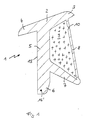
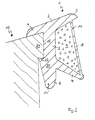
- the sealing profile shown there in cross section is approximately T-shaped.
- the crossbar of the T-shape is inclined to the horizontal and consists of an upper profile part 2, at the end of which the upper sealing lip 3 and the covering lip 4 are located.
- the trunk of the T-shape is formed by the vertical profile part 5, at the end of which the sealing foot 6 is located.
- a lower sealing lip 7 that extends obliquely downwards spreads out.
- the end of the lower sealing lip 7 is seen in the horizontal direction further from the vertical profile part 5 than the end of the upper sealing lip 3.
- the end of the lower sealing lip 7 is connected to the upper profile part 2 via a scribe lip 8 so that the upper sealing lip 3rd presents itself as a cantilevered, free profile part.
- the upper profile part 2, the scribing lip 8, the lower sealing lip 7 and parts of the vertical profile part 5 enclose a cavity 9 which is filled with a sealant.
- FIG. 1 The arrangement of a predetermined tear point 10 can be seen in FIG. 1 in the upper region of the scribing lip 8.
- the functioning and task of the individual parts can best be explained with reference to FIG. 4.
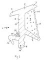
- FIG. 2 shows a cross section through a further sealing profile according to the invention, which differs from the sealing profile shown in FIG. 1 by the additional arrangement of a further cavity 11 and the arrangement of a projecting sealing lip 12.
- the additional cavity 11 is also filled with a sealant.
- the other parts correspond essentially to the sealing profile according to FIG. 1.
- the task and mode of operation of the individual parts result from the description of FIG. 4.
- the sealing lip 12 functions primarily as an anchoring foot.
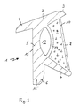
- FIG. 3 shows a further variant of the sealing profile 1 according to the invention, which essentially corresponds to the sealing profile 1 shown in FIG. 1.
- the only difference in the sealing profile 1 according to FIG. 3 is the arrangement of a further cavity 13 which is arranged adjacent to the cavity 9 and is separated from it by a sealing web part 14.
- the further cavity 13 is only filled with air, so it has no sealant.
- the cavity 13 has a compensating function in the installed state of the sealing profile.
- the scribe lip 8 tears when the window pane is installed and pressed against the sealing profile 1, as a result of which the cavity 9 and thus also the sealant therein are compressed.
- the cavity 13 is reduced accordingly, so that it is ensured that no sealant can escape from the sealing profile 1.
- the sealing web part which lies between the filled cavity 9 and the further cavity 13, is designed to be correspondingly thinner.
- the thickness of the sealing web part 14 can be varied so that a pressure which is passed on to the further cavity 13 via the sealant of the cavity 9 requires a correspondingly greater or smaller compression of the cavity 13.
- a double-sided adhesive tape 15 is provided over part of the height of the vertical profile part 5. This double-sided adhesive tape 15 is actually not necessary in the sealing profile shown in FIGS. 2 + 5, but can nevertheless be provided as an additional measure.
- All sealing profiles have an inserted thread 16 'in the area of the sealing foot 6.
- the thread 16 ' is arranged in the sealing foot 6 so that it is enclosed on all sides by the material of the sealing profile 1. In the miter area, it is necessary to cut the sealing profile 1 accordingly. The incision is made shortly before the thread 16 '.
- the thread 16 ' now ensures that the weak point that arises in the miter area during assembly and in the installed state does not tear, since the thread can absorb tensile stresses.
- the sealing profile 1 does not gap in the miter area even if, for example due to external influences, the sealing profile 1 is shortened in its longitudinal direction, since the thread also creates tensile stresses in the miter area installed condition can safely record.
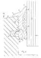
- Fig. 4 shows the sealing profile 1 of FIG. 2 in the installed state.
- the weather side of a wooden window corner area is shown in cross section.
- the sealing profile 1 has a projecting sealing lip 12 which engages in the horizontal recess or groove 17 of the window frame 16 and interacts with it the cover lip 4 clamps on the projecting part 18 of the window frame.
- the window pane or the insulating glass 19 shown is first clogged in the window frame 16. The block is not shown. Then the insulating glass 19 is pressed against the sealing profile 1. Due to the oblique arrangement of the upper sealing lip 3 and the lower sealing lip 7, they each deflect outwards, i.e. the upper sealing lip 3 is pressed upwards and the lower sealing lip 7 downwards. The scribing lip 8 is stretched and is thus under tension.
- the sealing lip 8 Since the sealing lip 8 is thin in relation to the other profile cross-sectional parts and also has a predetermined tear point 10, the scribing lip 8 will tear open during the pressing of the insulating glass 19 against the sealing profile 1.
- the sealing material located in the cavity 9 can thus emerge and seal on the insulating glass 19.
- the scribing lip 8 can also have a non-illustrated, pre-stressed insert on the side facing the cavity 9 or can be designed in such a way that the named side is under greater tension than the opposite side. Because of this pretension, the scribing lip 8 will roll up, starting at the predetermined breaking point 10, so that an even larger area is released in which the sealing material seals the insulating glass 19.
- the predetermined tear point 20 is arranged in a scribing lip 26 which seals the cavity 11 to the outside, the cross section of the further scribing lip 26 being thin in relation to the other profile cross sections.
- the predetermined tear point 20 is arranged so that it is exactly opposite the lower edge 21 in the installed state. Due to the contact pressure and due to the interaction between the lower edge 21 and the predetermined tear point 20, the additional cavity 11 is torn open and the sealing material therein can escape and seal the area of the lower edge 21 of the projecting part 18.
- the seal described is intended to ensure that moisture does not penetrate into the interior on the side between window frame 16 and sealing profile 1. Due to the inclined surface 22 of the window frame 16 and the arrangement of the cover lip 4 penetration of moisture is largely prevented, but it can still happen that moisture penetrates into the space between the window frame 16 and the sealing profile due to damage or other circumstances. In order that this moisture cannot penetrate into the interior between the window frame and insulating glass 19, the lower edge 21 of the projecting part 18 is additionally sealed by the sealant located in the hollow chamber 11.
- a first protection against the ingress of moisture is therefore first of all due to the inclined surface 22 of the window frame 16 and the cover lip 4 and the upper sealing lip 3. Reliable and safe protection against the ingress of moisture and to prevent heat loss is then by the in the hollow chambers 9 and 11 located sealing material guaranteed.
- the sealing material is protected from premature signs of aging, since it is not directly exposed to the weather, but is protected by the sealing profile 1.
- polysulfides for example thiokol
- acrylic resins or acrylic rubber or the like can also be used.
- FIG. 5 shows a further variant of a sealing profile 1 according to the invention according to FIG. 1 in the clamped state on the window frame 16.
- the essential difference between the sealing profile 1 from FIG. 5 and the sealing profile 1 from FIG. 1 is the arrangement of a step 23 in the central region of the vertical profile part 5.
- the window frame 16 is designed such that it is on its vertical side facing the sealing profile jumps back, so that seen in the vertical direction, an extension 24 is formed.
- the distance between the underside of the covering lip 4 and the step 23 corresponds to the height of the extension piece 24.
- a double-sided adhesive tape 15 can also be provided on the surface of the sealing profile 1 opposite the attachment piece 24.
- sealing profile 1 shown in FIG. 5 It is also possible with the sealing profile 1 shown in FIG. 5 to subsequently press the sealing profile 1 into the gap between the window frame 16 and the window pane when the window pane is already installed.
- the correct and firm fit of the sealing profile 1 is ensured in that the step-like cross-sectional widening 25 of the vertical profile part snaps under the extension 24 of the window frame 16.
- the snapped-in state can be recognized from the fact that the sealing profile 1, in the snapped-in state, bears in the upper region under tension against the window frame 16 and against the window pane.
- the sealing profile 1 can also be used in other than wooden window frames, e.g. also plastic or aluminum window frames can be used, whereby the advantages can be seen especially in the sealing of wooden windows.
- a further cavity 11 can be provided in the corner region between the upper cover lip 4 and the vertical profile part 5, the predetermined tear point 20 then being oriented approximately obliquely downwards.
Landscapes
- Engineering & Computer Science (AREA)
- Civil Engineering (AREA)
- Structural Engineering (AREA)
- Securing Of Glass Panes Or The Like (AREA)
- Glass Compositions (AREA)
- Materials For Medical Uses (AREA)
- Diaphragms For Electromechanical Transducers (AREA)
- Secondary Cells (AREA)
Abstract
Description
- Die Erfindung betrifft ein Dichtungsprofil, insbesondere zum Abdichten zwischen einem Fensterrahmen und der dazugehörigen Fensterscheibe, gemäß dem Oberbegriff des Anspruchs 1 sowie ein Verfahren zur Herstellung eines solchen Dichtungsprofils gemäß dem Oberbegriff des Anspruchs 9.
- Dichtungsprofile finden im allgemeinen dort Anwendung, wo ein unerwünschter Wärme- oder Feuchtigkeitsdurchgang verhindert werden soll. Insbesondere finden Dichtungsprofile beim Abdichten zwischen einem Fensterrahmen und der dazugehörigen Fensterscheibe Anwendung, um zu verhindern, daß beispielsweise Feuchtigkeit von der Wetterseite des Fensters auf deren Innenseite dringen kann bzw. in den Fensterrahmen an sich eindringt.
- Bei Holzfenstern ist es bisher üblich, daß die Fenster- bzw. Isolierglasscheibe im Fensterrahmen aufgeklotzt wird und anschließend auf der Wetterseite eine Kitt- oder Silikonverbindung angebracht wird. Auf der Innenseite wird eine sog. Glasleiste, die wie der Rahmen ebenfalls aus Holz besteht, nach Einbringen eines Dichtungsmaterials an die Innenseite der Isolierglasscheibe gedrückt und dann beispielsweise durch Nagelung an dem innenliegenden Holzrahmen befestigt. Der Spalt zwischen Glasleiste und Isolierglasscheibe, der im Regelfall minimal ist, kann zusätzlich durch Aufbringen von weiterem Dichtmaterial wie Kitt oder Silikon abgedichtet werden. Durch das Andrücken der Glasleiste an die Innenseite der Isolierglasscheibe wird das auf der Wetterseite der Isolierglasscheibe befindliche Dichtmaterial etwas zusammengedrückt, wodurch zunächst eine ausreichende Abdichtung erhalten werden kann.
- Es hat sich jedoch gezeigt, daß innerhalb einer relativ kurzen Zeitspanne das Dichtmaterial auf der Wetterseite brüchig wird oder schrumpft oder sich auf irgendeine andere Weise von dem abzudichtenden Bereich abhebt. Ungewöhnlich schnelle Alterungseffekte haben sich bei der Kittdichtung eingestellt, so daß in der letzten Zeit auch Silikon als Dichtmaterial Verwendung gefunden hat. Jedoch auch bei dem Dichtmaterial Silikon läßt der Anpreßdruck innerhalb einer kurzen Zeit sehr stark nach, so daß sich Spalten zwischen dem Dichtmaterial und der Isolierglasscheibe bzw. dem Dichtmaterial und dem Holzrahmen bilden. Durch diese Spalte kann Feuchtigkeit in das Innere des Holzrahmens über Dampfdiffusion eindringen, so daß das Holz aufquillt und/oder die Lackschicht in den feuchten Bereichen abgedrückt wird. Durch das Eindringen von Feuchtigkeit in den Holzrahmen kann sich auch ein unerwünschter Feuchtigkeitsniederschlag in dem Zwischenraum oder den Zwischenräumen bei Mehrfachverglasung bilden.
- Ein dem Dichtungsprofil der eingangs genannten Art vergleichbares Profil ist bei der Abdichtung von Autofenstern aus der EP 2 140 068 A bekannt. Dieses Dichtungsprofil weist einen Hohlraum auf, der ebenfalls ein Dichtmaterial aufnimmt. Beim vertikalen Aufsetzen des Fensters auf diesen Dichtungsbereich wird eine membranartige Sollreißstelle zerrissen. Der Austritt des Dichtmaterials wird jedoch dadurch erschwert, daß die auf der Innenseite des Fensters zu liegen kommende Dichtwandung relativ umständlich aus ihrer weitgehend Horizontallage unter der Fensterunterkante hervorgeholt werden muß. Weiterhin ist diese innere Dichtwandung anschließend in ihrer vertikalen Ausrichtung durch Einbringen eines Stützgliedes zu stabilisieren.
- Aus der US-PS 3,061,895 ist weiterhin ein anderes Dichtungsprofil bekannt, das in zwei Hohlräumen Dichtmaterial aufnimmt. Es ist dort jedoch vorgesehen, das Dichtmaterial nach dem Extrudieren des Dichtungsprofils bzw. später einzubringen.
- Die beiden vorgenannten Dichtungsprofile eignen sich daher nicht für den speziellen Einsatz bei Holz-Fensterrahmen und aufgeklotzten Fensterscheiben, da für diese Zwecke eine optimale Außenabdichtung der Fensterscheibe erforderlich ist.
- Es ist Aufgabe der vorliegenden Erfindung, ein Dichtungsprofil zur Verfügung zu stellen, mit welchem eine bessere und dauerhafte Abdichtung insbesondere zwischen einem Fensterrahmen und der dazugehörigen Fensterscheibe erreicht werden kann. Weiterhin soll das vorgeschlagene Dichtungsprofil insbesondere bei Fenstern mit Holzrahmen eine solche bessere und dauerhafte Abdichtung gewährleisten.
- Daneben ist es ebenfalls Aufgabe der vorliegenden Erfindung, ein Verfahren zur Herstellung eines solchen Dichtungsprofils anzugeben, mit welchem auf schnelle und zuverlässige Art und Weise ein Dichtungsprofil mit mindestens zwei Materialien hergestellt werden kann.
- Diese Aufgabe wird bei einem gattungsgemäßen Dichtungsprofil bzw. bei einem gattungsgemäßen Verfahren durch die kennzeichnenden Merkmale des Anspruchs 1 bzw. die kennzeichnenden Merkmale des Anspruchs 9 gelöst.
- Anstelle von Kitt oder Silikon, welche nach dem Aufklotzen der Fensterscheibe auf der Wetterseite in den Spalt zwischen Fensterrahmen und Fensterscheibe gepreßt werden, soll ein besonders ausgestaltetes Dichtungsprofil Verwendung finden. Das Dichtungsprofil wird dabei vor dem Aufklotzen der Fenstersoheibe oder des Isolierglases an dem abzudichtenden Bereich des Fensterrahmens angebracht. Erst danach wird die Fensterscheibe gegen das Profil gedrückt und auf der Innenseite beispielsweise mit einer Glasleiste befestigt. Es ist auch denkbar, bei bestimmten Dichtungsprofilformen, die Glasscheibe zuerst aufzuklotzen und das vorgeschlagene Dichtungsprofil danach in den sich zwischen Fensterrahmen und Fensterscheibe ergebenden Spalt einzulegen. Diese Vorgehensweise kann insbesondere dann vorteilhaft sein, wenn das verwendete Dichtungsprofil aufgrund seiner Querschnittsform sich an den Fensterrahmen alleine nicht ausreichend festklemmen kann, so daß z.B. die Gefahr besteht, daß Teile des Dichtungsprofiles vor dem Aufklotzen der Fensterscheibe sich aus ihrer vorbestimmten Lage wegbewegen.
- Dadurch, daß bei dem verwendetem Dichtungsprofil mindestens ein Hohlraum mit einem Füllmaterial ausgefüllt ist und dadurch, daß die dem abzudichtenden Bereich zugewandte Wandung der gefüllten Hohlkammer im Verhältnis zu den übrigen Wandstärken dünn ausgebildet ist, kann eine hervorragende Dichtung dadurch erreicht werden, daß der gefüllte Hohlraum beim Anpressen der Fensterscheibe in Richtung auf die Wetterseite aufreißt oder platzt und das Füllmaterial sich auf dem abzudichtenden Bereich verteilt und zusätzlich in entstandene Ritzen oder Spalten eindringen kann. Durch die im Regelfall vertikale Anordnung der Fensterscheibe ist der Bereich zwischen Füllmaterial und Fensterscheibe in Bezug auf das Eindringen von Feuchtigkeit besonders gefährdet, da Regenwasser an der Wetterseite der Fensterscheibe nach unten über das Füllmaterial und den sich anschließenden Fensterrahmen abläuft. Deshalb muß der vorgenannte Bereich ganz besonders zuverlässig abgedichtet werden. Diesem Umstand wird in vorteilhafter Weise dadurch Rechnung getragen, daß die dünn ausgebildete Wandung des gefüllten Hohlraums der Fensterscheibe zugewandt ist, wobei sich der Hohlraum über den größten Teil der Dichtungsprofilhöhe erstreckt.
- Im Regelfall ist es durch die Verwendung eines Dichtungsprofiles nicht erforderlich, daß auch der Bereich zwischen Fensterrahmen und Dichtungsprofil zusätzlich über einen mit Füllmaterial gefüllten Hohlraum erfolgt. Jedenfalls braucht in diesem Bereich keine allzu große Fläche abgedichtet werden, so daß es als zusätzliche Sicherheit bereits genügt, wenn ein solcher gefüllter Hohlraum im Bereich einer Kante des Holzrahmens angeordnet ist. Bei dieser Kante kann es sich entweder um die obere Kante des Holzrahmens handeln oder um eine Kante, die durch Anordnung eines horizontalen Einschnittes des Fensterrahmens zur Aufnahme einer auskragenden Dichtlippe des Dichtungsprofiles entsteht.
- In allen Fällen sind die mit Füllmaterial gefüllten Hohlräume des Dichtungsprofiles so konzipiert, daß sie durch den Andruck der Fensterscheibe beim Festklemmen der Fensterscheibe zuverlässig aufreissen oder aufplatzen, um so das Füllmaterial zuverlässig und sicher zu verteilen. Das Füll- bzw. Dichtungsmaterial ist auch im abgedichteten Zustand des Fensters durch die Ausgestaltung des Dichtungsprofiles voll abgedeckt und somit geschützt. Äußere witterungsbedingte Einflüsse tragen somit in vorteilhafter Weise in wesentlich geringerem Umfang zu einer Alterung und somit zu einer Veränderung des Füllmaterials bei. Das Füllmaterial wird sich über einen größeren Zeitraum, selbst wenn es durch das Dichtungsprofil an sich geschützt ist, möglicherweise verändern, d.h. eventuell schrumpfen. Dabei ist jedoch die Anordnung des Dichtungsprofils von ganz herausragendem Vorteil, da das Dichtungsprofil durch das Andrücken der Fensterscheibe unter Spannung steht und aufgrund dieser Spannung eventuelle Schrumpfungen des Füllmaterials ausgleichen kann, so daß ein Entstehen von Spalten oder luftgefüllten Hohlräumen zuverlässig verhindert wird.
- Es ist bei der vorliegenden Erfindung von besonderem Vorteil, daß als Füllmaterial ein Dichtmaterial, z.B.auf Silikonbasis Verwendung findet. Da das Füllmaterial die Aufgabe hat, eine Sicherheit gegen Eindringen von Feuchtigkeit und Verlust von Wärme zu bieten, wird als Füllmaterial in vorteilhafter Weise ein Dichtmaterial verwendet. Dabei hat sich insbesondere Silikon als vorteilhaft herausgestellt, da Silikon unter Luftabschluß seinen flüssigen Zustand behält und erst unter Lufteinfluß aushärtet. Somit kann das Silikon nach dem Aufreissen des Hohlraumes des Dichtungsprofiles zunächst in alle abzudichtenden Bereiche dringen bzw. sie benetzen.
- Es ist weiterhin von besonderem Vorteil, daß die dem abzudichtenden Bereich zugewandte Wandung des gefüllten Hohlraums eine Sollreißstelle aufweist. Um das sichere Aufreissen des mit dem Füllmaterial gefüllten Hohlraumes sicherzustellen, kann in vorteilhafter Weise in die dem abzudichtenden Bereich zugewandte Wandung eine Sollreißstelle eingebaut werden, so daß beim Andrücken der Fensterscheibe und dem dadurch in dem gefüllten Hohlraum entstehenden Druck ein Aufreissen nicht nur völlig gesichert ist, sondern auch an einer ganz bestimmten, vorbestimmbaren Stelle erfolgen kann. So kann ein Aufreissen der Wandung des gefüllten Hohlraumes an den Stellen vorbestimmt werden, an denen eine Abdichtung unbedingt erforderlich ist.
- Es ist auch weiterhin von besonderem Vorteil, daß die Sollreißstelle nach dem Einbau des Dichtungsprofils einer Kante des abzudichtenden Bereichs gegenüberliegt. Dies trifft insbesondere für den Bereich zwischen dem Holzrahmen und dem Dichtungsprofil zu, da ein dort angeordneter gefüllter Hohlraum möglicherweise durch das Andrücken der Fensterscheibe an das Dichtungsprofil nicht so sehr, aufgrund des Materials des Dichtungsprofiles, unter Druck steht, wie dies bei dem der Fensterscheibe zugewandten Hohlraum der Fall ist. Um jedoch trotzdem sicherzustellen, daß auch dieser im Bereich des Fensterrahmens angeordnete Hohlraum zuverlässig aufreißt oder aufplatzt, wird die Sollreißstelle am günstigsten an einer Kante des Fensterrahmens placiert. Somit reicht schon ein geringer Druck, um die Sollreißstelle zum Reissen zu bringen.
- Weiterhin ist es von ganz besonderem Vorteil, daß mindestens ein Hohlraum mit Luft gefüllt ist, der in vorteilhafter Weise in der Nähe der gefüllten Hohlkammer angeordnet ist. Durch das Andrücken der Fensterscheibe gegen die Profildichtung und das anschließende Aufreissen des mit Füllmaterial gefüllten Hohlraumes kann es möglich sein, daß aufgrund zu festen Andrückens der Fensterscheibe gegen das Dichtungsprofil ein Teil des Füllmaterials aus dem Hohlraum und dem Dichtungsprofil nach außen gedrückt wird. Dies ist jedoch nicht erwünscht, da einerseits das Dichtungsprofil sowie die angrenzende Fensterscheibe bzw. der Fensterrahmen verschmutzt werden und andererseits Füll- bzw. Dichtmaterial verlorengeht. Aus diesem Grunde kann ein mit Luft gefüllter Hohlraum in der Nähe der mit Dichtmaterial gefüllten Hohlkammer angeordnet sein. Wenn nun der Druck gegen das Dichtmaterial zu stark ist, wird sich, bevor das Dichtmaterial aus dem Dichtungsprofil gequetscht wird, der mit Luft gefüllte Hohlraum eindrücken, so daß zusätzlicher Raum für das Dichtmaterial geschaffen wird. Die Wandungsdicke des mit Luft gefüllten Hohlraumes zu dem mit Dichtmaterial gefüllten Hohlraum sowie die Querschnittsgröße des mit Luft gefüllten Hohlraums können so abgestimmt werden, daß ein Austreten bzw. Unterfließen des Dichtmaterials unter die Dichtlippen oder den Dichtbereich zuverlässig vermeiden werden kann.
- Es ist weiterhin von Vorteil, daß nach dem Einsetzen der Fensterscheibe der oder die Hohlräume komprimiert werden und daß sich der obere und untere Bereich des an der Fensterscheibe anliegenden Dichtungsprofils durch das Einsetzen der Fensterscheibe jeweils nach außen abspreizt. Die Vorteile des Komprimierens der Hohlräume liegen wie besprochen einerseits darin, daß das Dichtmaterial durch das Komprimieren zuverlässig an alle gewünschten Stellen gedrückt wird und andererseits durch das Komprimieren eines mit Luft gefüllten Hohlraumes je nach Bedarf Platz für das Dichtmaterial geschaffen werden kann. Der obere und der untere Bereich des an der Fensterscheibe anliegenden Dichtungsprofils kann sich aufgrund des Andrückens der Fensterscheibe und des Reissens der der Fensterscheibe zugewandten Wandung jeweils nach außen abspreizen. Durch dieses Abspreizen werden die genannten Bereiche des Dichtungsprofils unter Spannung gesetzt und liegen somit dicht und sicher an der Fensterscheibe an. Auch vergrößert sich dadurch der der Fensterscheibe zugewandte Bereich der Hohlkammer, so daß dadurch eine wesentlich größere Fläche mit dem Dichtmaterial benetzt werden kann. D.h., der abzudichtende Bereich vergrößert sich erheblich. Schon allein durch das Anpressen des oberen Bereiches des Dichtprofiles, der sog. oberen Dichtlippe, wird ein erster und zuverlässiger Schutz gegen Eindringen von Feuchtigkeit und Verlust von Wärme geschaffen. Im unteren Bereich des Dichtungsprofils, nämlich im Bereich der unteren Dichtlippe, sorgt die Spannung dafür, daß das Dichtungsprofil fest und unverrückbar in dem Spalt zwischen Fensterrahmen und Fensterscheibe festgeklemmt ist.
- Bei der vorliegenden Erfindung ist es weiterhin von Vorteil, daß die dem abzudichtenden Bereich zugewandte Wandung der gefüllten Hohlkammer eine in dem dem gefüllten Hohlraum zugewandten Bereich angeordnete, vorgespannte und in Längsrichtung des Dichtungsprofils durchgehende Einlage aufweist. Diese Einlage sorgt dafür, daß die eingerissene Wandung sich nach dem Riß aufgrund der vorhandenen Vorspannung aufrollt und somit den abzudichtenden Bereich vollständig freigibt. Es ist auch vorstellbar, daß aufgrund besonderer z.B.thermischer Verfahren beim Herstellen des Dichtungsprofils eine Faserverkürzung auf der genannten Seite der Wandung vorgesehen werden kann, so daß sich ein Aufrolleffekt nicht aufgrund einer vorgespannten Einlage, sondern aufgrund einer bereits beim Herstellen aufgebrachten Vorspannung ergibt.
- Es ist weiterhin von Vorteil, daß der der Fensterscheibenkante zugewandte untere Bereich des Dichtungsprofil einen in Längsrichtung des Dichtungsprofils durchgehenden Faden aufweist. Aufgrund dieses Fadens kann im Gehrungsbereich der nötige Einschnitt des Dichtungsprofiles vorgenommen werden, ohne daß die vorhandene Festigkeit des Dichtungsprofiles in diesem Bereich vorlorengeht und ohne daß die Gefahr besteht, daß das Dichtungsprofil im Gehrungsbereich völlig durchtrennt wird. Das Aufschneiden des Dichtungsprofiles im Gehrungsbereich hat bei der vorliegenden Ausgestaltung des Dichtungsprofiles den weiteren Vorteil, daß beim Einschneiden des Dichtungsprofiles an beiden Seiten etwas Dichtmittel ausfließen wird, so daß beim Umklappen des Dichtungsprofiles - im Regelfall um 90° - der Effekt auftritt, daß das Dichtungsprofil im Gehrungsbereich aufgrund des ausgetretenen Dichtmittels verklebt wird und somit der anfällige Gehrungsbereich zuverlässig dicht gehalten werden kann.
- Es ist weiterhin von Vorteil, daß im unteren,der Fensterscheibe abgewandten Bereich des Dichtungsprofils eine auskragende Dichtlippe angeordnet ist. Diese Dichtlippe hat den Vorteil, daß bei der Montage des Dichtungsprofils am Fensterrahmen - vor dem Anlegen bzw. Anpressen der Fensterscheibe gegen das Dichtungsprofil - das Dichtungsprofil am Fensterrahmen festgeklemmt werden kann. Entsprechend der auskragenden Dichtlippe, die etwas nach schräg oben von der Horizontalen aus gesehen, angeordnet ist, weist der Fensterrahmen einen horizontal verlaufenden Einschnitt auf, in den die auskragende Dichtlippe eingeschoben werden kann. Dabei muß die Dichtlippe etwas nach unten gebogen werden, so daß sie beim vollständigen Einbringen in die horizontale Aussparung im Zusammenspiel mit der oberen Abdecklippe einen Klemmeffekt ergibt. Das Dichtungsprofil kann also zunächst an dem Fensterrahmen festgeklemmt werden, ohne daß zu befürchten ist, daß sich während oder vor dem Montieren der Fensterscheibe das Dichtungsprofil entweder ganz oder teilweise von dem Fensterrahmen löst.
- Es ist auch von besonderem Vorteil, daß das Dichtungsprofil aus Elastomeren, insbesondere aus PVC oder Thermo-Kautschuk/ TPE hergestellt ist. Elastomere haben sich bei der Herstellung von Dichtungsprofilen und den Aufgaben von Dichtungsprofilen als sehr zuverlässig erwiesen. Daneben ist die Verwendung der vorgenannten Materialien auch kostengünstig. Darüberhinaus sind die Witterungseinflüsse auf die vorgenannten Materialien außerordentlich gering.
- Bei der Herstellung eines solchen Dichtungsprofiles ist es von besonderem Vorteil, daß unmittelbar nach dem Bilden des Hohlraumes vor dem Austreten des gesamten Dichtungsprofiles aus der Spritzplatte das Füllmaterial in den Hohlraum gepreßt wird. Somit kann in einem Arbeitsgang ein beliebig langes Dichtungsband hergestellt werden, das in mindestens einem Hohlraum sofort mit Füllmaterial ausgefüllt ist, ohne daß etwa anschließend mit Hilfe einer zweiten Vorrichtung bestimmte Hohlräume mit Füllmaterial gefüllt werden müssen. Durch das vorgeschlagene Verfahren ist auch sichergestellt, daß sich bei der Füllung des Hohlraumes keine Blasen oder ungefüllte Abschnitte ergeben können, da entsprechend dem Hohlraumquerschnitt eine entsprechende Füllmaterialmenge in den Hohlraum eingedrückt wird. Ein weiterer Vorteil bei dem vorgeschlagenen Verfahren besteht darin, daß eine herkömmliche Extrusionsmaschine Verwendung finden kann und lediglich die Spritzplatte bzw. ein Teil der Spritzplatte verändert werden muß. Das vorgeschlagene Verfahren hat zudem den Vorteil, daß die Herstellungsgeschwindigkeit gegenüber normalen Dichtungsprofilen mit ungefüllten Hohlräumen gleich ist. Es tritt also bei der Herstellung kein Zeitverlust ein. Das vorgeschlagene Dichtungsprofil kann zudem wie ein Dichtungsprofil mit ungefüllten Hohlräumen gelagert und transportiert werden.
- Es ist weiterhin von Vorteil, daß beim Extrudieren des Dichtungsprofiles ein Faden in einen der Profilquerschnitte des Dichtungsprofiles eingelegt wird, so daß der Faden völlig vom Material des Dichtungsprofiles umgeben wird. Auch bei dem vorgeschlagenen Verfahren ist es möglich, einen zusätzlichen Verfahrensschritt einzubauen, mit Hilfe dessen ein Faden in das Dichtungsprofil eingeführt werden kann, so daß die Vorteile der Anordnung eines Fadens im Dichtungsprofil, wie vorgenannt, auch bei dem vorgeschlagenen Verfahren ausgenutzt werden können.
- Es ist bei dem vorgeschlagenen Verfahren weiterhin von Vorteil, daß das Dichtungsprofil aus Elastomeren, insbesondere aus PVC oder Thermo-Kautschuk/TPE hergestellt wird. Mit den vorgenannten Elastomeren kann ein kostengünstiges und sicheres Herstellen im Extrusionsverfahren garantiert werden.
- Bei dem vorgeschlagenen Verfahren ist es auch von Vorteil, daß als Füllmaterial ein Dichtmaterial, insbesondere Silikon, verwendet wird. Die Einsatzgebiete der mit dem vorgeschlagenen Verfahren hergestellten Dichtungsprofile haben gezeigt, daß es von Vorteil ist, wenn als Füllmaterial ein Dichtmaterial Verwendung findet, so daß eine hohe Sicherheit gegen das Eindringen von Feuchtigkeit und gegen Wärmeverlust erreicht wird. Dabei hat sich insbesondere Silikon als sehr zuverlässig und kostengünstig erwiesen.
- Es ist weiterhin von besonderem Vorteil, daß die dem Fensterrahmen zugewandte Fläche des vertikalen Profilteiles ein doppelseitiges Klebeband aufweist. Mit Hilfe dieses Klebebandes kann das Dichtungsprofil sicher und fest an dem Fensterrahmen gehalten werden, wenn zunächst das Dichtungsprofil an der Kante des Fensterrahmens angebracht wird und die Fensterscheibe noch nicht eingesetzt ist. In diesem Zwischenzustand, in welchem das Dichtungsprofil durch die Fensterscheibe noch nicht gehalten ist, wird ein Herunterfallen oder Ablösen des Dichtungsprofiles sicher und zuverlässig verhindert, selbst wenn beim Einsetzen der Fensterscheibe das Dichtungsprofil von der falschen Seite her gedrückt oder geschoben werden sollte.
- Es ist gleichfalls von besonderem Vorteil, daß Dichtungsprofile zur Anwendung kommen können, deren Hohlräume nicht oder nicht alle mit Füll- bzw. Dichtmaterial ausgefüllt sind. Nach dem Einbau der Fensterscheibe in den Fensterrahmen ist es nämlich möglich, die obere Dichtlippe etwas abzuheben, so daß erforderlichenfalls nachträglich von außen her Füll- bzw. Dichtmaterial zwischen das Dichtungsprofil und die Fensterscheibe gepreßt werden kann. Je nach Einpreßdruck ist es dann gleichfalls möglich, ungewollt oder gewollt freigelassene Hohlräume zwischen dem Dichtungsprofil und der Fensterscheibe mit Füll- bzw. Dichtmaterial vollzupressen. Bei Verwendung einer entsprechenden Einspritzvorrichtung, insbesondere deren Endteil kann sichergestellt werden, daß einerseits ein zuverlässiges Auffüllen von Hohlräumen sichergestellt ist und andererseits das Dichtungsprofil im Bereich seiner oberen Dichtlippe nicht verletzt wird. Aufgrund der Elastizität des Dichtungsprofils legt sich dieses bei erfolgtem nachträglichem Einfüllen von Dicht- bzw. Füllmaterial sofort wieder sicher und fest an die Fensterscheibe an.
- Es ist darüberhinaus von besonderem Vorteil, daß das vertikale Profilteil in seinem mittleren Bereich eine stufenartige Querschnittsverbreiterung auf der dem Fensterrahmen zugewandten Seite aufweist. Diese stufenartige Querschnittsverbreiterung ist insbesondere dann von Vorteil, wenn der Fensterrahmen im oberen, der Fensterscheibe zugewandten Bereich einen sich vertikal ersteckenden Vorsprung aufweist. Die stufenartige Querschnittsverbreiterung untergreift den Fensterrahmenvorsprung und erzeugt somit einen Klemmeffekt des Dichtungsprofiles am Fensterrahmen. Mit einem Dichtungsprofil, welches eine solche stufenartige Querschnittsverbreiterung aufweist, ist es insbesondere möglich, in vorteilhafter Weise das Dichtungsprofil auch einzubringen, nachdem die Fensterscheibe bereits im Fensterrahmen eingesetzt ist. Das Dichtungsprofil wird dann zwischen Fensterrahmen und Fensterscheibe eingedrückt bzw. eingerollt und erhält dadurch seinen festen und exakten Sitz, wobei die stufenartige Querschnittsverbreiterung den Fensterrahmenvorsprung untergreift bzw. in diesen Vorsprung einschnappt. Das nachträgliche Einbringen von Dichtungsprofilen ist beispielsweise dann erforderlich, wenn bei gebrauchten Holzfenstern die Dichtmaterialien, die unbrauchbar geworden sind, aus dem Spalt zwischen Fensterrahmen und Fenster abschnittsweise herausgenommen werden. Anstelle des üblichen erneuten Einbringens von Dichtmaterialien, wie Kitt und Silikon, kann dann das vorgeschlagene Dichtungsprofil in den entstehenden Spalt eingedrückt werden. Daneben hat die stufenartige Querschnittsverbreiterung bei üblicher Montage den gleichen Effekt, den auch eine auskragende Dichtlippe aufweist, nämlich einen Klemmeffekt am Fensterrahmen, bevor die Fensterscheibe eingesetzt wird.
- Die vorliegende Erfindung soll im nachfolgenden anhand verschiedener Ausführungsbeispiele weiter erläutert werden. Es zeigen dabei:
- Fig. 1
- einen Querschnitt durch ein erfindungsgemäßes Dichtungsprofil mit einem gefüllten Hohlraum,
- Fig. 2
- einen Querschnitt durch ein erfindungsgemäßes Dichtungsprofil mit zwei gefüllten Hohlräumen und einer auskragenden Dichtlippe,
- Fig. 3
- einen Querschnitt durch ein erfindungsgemäßes Dichtungsprofil gemäß Fig. 1, wobei zusätzlich ein nicht gefüllter Hohlraum vorgesehen ist,
- Fig. 4
- das Dichtungsprofil gemäß Fig. 2 in eingebautem Zustand und
- Fig. 5
- einen Querschnitt durch ein weiteres erfindungsgemäßes Dichtungsprofil nach Fig. 1 in am Fensterrahmen eingeklemmtem Zustand, wobei zusätzlich eine Querschnittsverbreiterung vorgesehen ist.
- Identische Teile werden in den Figuren mit gleichen Ziffern beschriftet.
- Nach Fig. 1 weist das dort im Querschnitt gezeigte Dichtungsprofil etwa T-Form auf. Der Querbalken der T-Form ist dabei gegen die Horizontale geneigt und besteht aus einem oberen Profilteil 2, an dessen Ende sich die obere Dichtlippe 3 und die Abdecklippe 4 befinden. Der Stamm der T-Form wird durch das vertikale Profilteil 5 gebildet, an dessen Ende sich der Dichtungsfuß 6 befindet. Ungefähr am Anfang des letzten Drittels des vertikalen Profilteiles 5 spreizt eine, schräg nach unten verlaufende untere Dichtlippe 7 ab. Das Ende der unteren Dichtlippe 7 ist in horizontaler Richtung gesehen weiter von dem vertikalen Profilteil 5 entfernt als das Ende der oberen Dichtlippe 3. Das Ende der unteren Dichtlippe 7 ist mit dem oberen Profilteil 2 über eine Anreißlippe 8 so verbunden, daß die obere Dichtlippe 3 sich als auskragendes, freies Profilteil darstellt.
- Das obere Profilteil 2, die Anreißlippe 8, die untere Dichtlippe 7 und Teile des vertikalen Profilteils 5 umschließen einen Hohlraum 9, der mit einem Dichtmittel ausgefüllt ist.
- Im oberen Bereich der Anreißlippe 8 ist aus der Fig. 1 die Anordnung einer Sollreißstelle 10 zu erkennen. Die Funktionsweise und Aufgabe der einzelnen Teile lassen sich am besten anhand von Fig. 4 erklären.
- Fig. 2 zeigt einen Querschnitt durch ein weiteres erfindungsgemäßes Dichtungsprofil, welches sich von dem in Fig. 1 gezeigten Dichtungsprofil durch die zusätzliche Anordnung eines weiteren Hohlraumes 11 und die Anordnung einer auskragenden Dichtlippe 12 unterscheidet. Der zusätzliche Hohlraum 11 ist ebenfalls mit einem Dichtmittel ausgefüllt. Die übrigen Teile entsprechen im wesentlichen dem Dichtungsprofil gemäß Fig. 1. Aufgabe und Wirkungsweise der einzelnen Teile ergeben sich aus der Beschreibung zu Fig. 4. Die Dichtlippe 12 fungiert hierbei primär als Verankerungsfuß. Fig. 3 zeigt eine weitere Variante des erfindungsgemäßen Dichtungsprofiles 1, welches im wesentlichen dem in Fig. 1 gezeigten Dichtungsprofil 1 entspricht. Einziger Unterschied bei dem Dichtungsprofil 1 gemäß Fig. 3 ist die Anordnung eines weiteren Hohlraumes 13, der benachbart zu dem Hohlraum 9 angeordnet ist und von diesem durch ein Dichtungsstegteil 14 getrennt ist. Der weitere Hohlraum 13 ist dabei nur mit Luft gefüllt, weist also keinerlei Dichtungsmittel auf.
- Der Hohlraum 13 hat im eingebauten Zustand des Dichtungsprofils eine Ausgleichsfunktion. Wie zu Fig. 4 später beschrieben wird, reißt die Anreißlippe 8 beim Einbau und Anpressen der Fensterscheibe gegen das Dichtungsprofil 1, wodurch der Hohlraum 9 und somit auch das darin befindliche Dichtmittel komprimiert werden. Bevor nun das Dichtmittel im ungünstigsten Fall nach oben über die obere Dichtlippe 3 oder nach unten über die untere Dichtlippe 7 austritt, verringert sich der Hohlraum 13 entsprechend, so daß es sichergestellt ist, daß kein Dichtmittel aus dem Dichtungsprofil 1 austreten kann. Dazu ist das Dichtungsstegteil, welches zwischen dem gefüllten Hohlraum 9 und dem weiteren Hohlraum 13 liegt, entsprechend dünner ausgeausgestaltet. Je nach Bedürfnis und Anwendungsbereich kann die Dicke des Dichtungsstegteils 14 variiert werden, so daß ein Durck, der über das Dichtmittel des Hohlraumes 9 an den weiteren Hohlraum 13 weitergegeben wird, eine entsprechend größere oder kleinere Komprimierung des Hohlraumes 13 bedingt.
- Damit die gezeigten Dichtungsprofile, insbesondere die Profile gemäß Fig. 1 und 3 bei der Montage an dem Fensterrahmen sicher gehalten werden, ist ein doppelseitiges Klebeband 15 über einen Teil der Höhe des vertikalen Profilteiles 5 vorgesehen. Dieses doppelseitige Klebeband 15 ist bei dem in Fig. 2 + 5 gezeigten Dichtungsprofil eigentlich nicht notwendig, kann aber als zusätzliche Maßnahme trotzdem vorgesehen werden.
- Sämtliche Dichtungsprofile weisen im Bereich des Dichtungsfußes 6 einen eingelegten Faden 16' auf. Der Faden 16' ist in dem Dichtungsfuß 6 so angeordnet, daß er allseitig von dem Material des Dichtungsprofiles 1 umschlossen ist. Im Gehrungsbereich ist es erforderlich, das Dichtungsprofil 1 entsprechend einzuschneiden. Der Einschnitt erfolgt bis kurz vor den Faden 16'. Der Faden 16' sorgt nun dafür, daß die entstandene Schwachstelle im Gehrungsbereich bei der Montage sowie im eingebauten Zustand nicht reißt, da der Faden Zugspannungen aufnehmen kann. Dadurch, daß der Faden im Gehrungsbereich unbeschädigt erhalten bleibt, klafft das Dichtungsprofil 1 im Gehrungsbereich auch dann nicht auf, wenn sich beispielsweise aufgrund äusserer Einflüsse eine Verkürzung des Dichtungsprofils 1, in seiner Längsrichtung gesehen, ergibt, da der Faden im Gehrungsbereich entstehende Zugspannungen auch im eingebauten Zustand sicher aufnehmen kann.
- Fig. 4 zeigt das Dichtungsprofil 1 nach Fig. 2 im eingebauten Zustand. Dargestellt ist dabei die Wetterseite eines Holzfenster-Eckbereiches im Querschnitt.
- Im nachfolgenden soll beschrieben werden, wie der Einbau des Dichtungsprofiles 1 erfolgt:
- Zunächst wird das Dichtungsprofil 1 gemäß Fig. 2 auf den Fensterrahmen 16 aufgesteckt oder aufgeschoben, was dadurch ermöglicht wird, daß das Dichtungsprofil 1 eine auskragende Dichtlippe 12 aufweist, die in die horizontale Aussparung bzw. Nut 17 des Fensterrahmens 16 eingreift und sich im Zusammenspiel mit der Abdecklippe 4 an dem auskragenden Teil 18 des Fensterrahmens festklemmt. Danach wird die Fensterscheibe bzw. das dargestellte Isolierglas 19 zunächst im Fensterrahmen 16 aufgeklotzt. Die Aufklotzung ist dabei nicht dargestellt. Anschließend wird das Isolierglas 19 gegen das Dichtungsprofil 1 gedrückt. Aufgrund der schrägen Anordnung der oberen Dichtlippe 3 und der unteren Dichtlippe 7 weichen diese jeweils nach außen aus, d.h. die obere Dichtlippe 3 wird nach oben gedrückt und die untere Dichtlippe 7 nach unten. Dabei wird die Anreißlippe 8 gedehnt und steht dadurch unter Zugspannung. Da die Dichtlippe 8 im Verhältnis zu den übrigen Profilquerschnittsteilen dünn ausgebildet ist und zudem eine Sollreißstelle 10 aufweist, wird die Anreißlippe 8 während dem Anpressen des Isolierglases 19 gegen das Dichtungsprofil 1 aufreissen. Das in dem Hohlraum 9 befindliche Dichtmaterial kann somit austreten und am Isolierglas 19 abdichten. Durch die Spreizung der oberen Dichtlippe 3 und der unteren Dichtlippe 7 vergrößert sich der Bereich, in welchem das Dichtmaterial das Isolierglas 19 abdichtet. Die Anreißlippe 8 kann auch auf der dem Hohlraum 9 zugewandten Seite eine nicht dargestellte, vorgespannte Einlage aufweisen oder so konzipiert sein, daß die benannte Seite unter größerer Spannung steht als die gegenüberliegende Seite. Aufgrund dieser Vorspannung wird sich die Anreißlippe 8, beginnend an der Sollbruchstelle 10, aufrollen, so daß ein noch größerer Bereich freigegeben wird, in welchem das Dichtmaterial das Isolierglas 19 abdichtet.
- Der zusätzliche Hohlraum 11 , der ebenfalls mit Dichtmaterial gefüllt ist und eine Sollreißstelle 20 aufweist, wird gegen die untere Kante 21 des auskragenden Teils 18 gedrückt. Die Sollreißstelle 20 ist in einer Anreißlippe 26 angeordnet, die den Hohlraum 11 nach außen abdichtet, wobei der Querschnitt der weiteren Anreißlippe 26 im Verhältnis zu den übrigen Profilquerschnitten dünn ausgebildet ist. Die Sollreißstelle 20 ist dabei so angeordnet, daß sie im eingebauten Zustand der unteren Kante 21 genau gegenüberliegt. Aufgrund des Anpreßdruckes und aufgrund des Zusammenspiels zwischen der unteren Kante 21 und der Sollreißstelle 20 wird der zusätzliche Hohlraum 11 aufgerissen und däs darin befindliche Dichtmaterial kann austreten und den Bereich der unteren Kante 21 des auskragenden Teiles 18 abdichten. Die beschriebene Abdichtung soll sicherstellen, daß keinesfalls Feuchtigkeit in den Innenraum auf der Seite zwischen Fensterrahmen 16 und Dichtungsprofil 1 eindringt. Durch die schräge Fläche 22 des Fensterrahmens 16 und die Anordnung der Abdecklippe 4 ist zwar ein Eindringen von Feuchtigkeit weitgehend verhindert, es kann aber trotzdem vorkommen, daß aufgrund von Beschädigung oder anderen Umständen Feuchtigkeit in den Raum zwischen Fensterrahmen 16 und Dichtungsprofil eindringt. Damit diese Feuchtigkeit nicht in den Innenraum zwischen Fensterrahmen und Isolierglas 19 eindringen kann, ist die untere Kante 21 des auskragenden Teiles 18 zusätzlich durch das in der Hohlkammer 11 befindliche Dichtmittel abgedichtet.
- Ein erster Schutz gegen Eindringen von Feuchtigkeit erfolgt also zunächst aufgrund der schrägen Fläche 22 des Fensterrahmens 16 und der Abdecklippe 4 sowie der oberen Dichtlippe 3. Zuverlässiger und sicherer Schutz gegen Eindringen von Feuchtigkeit und zur Verhinderung von Wärmeverlusten ist dann durch das in den Hohlkammern 9 und 11 befindliche Dichtmaterial gewährleistet. Das Dichtmaterial ist dabei vor vorzeitigen Alterserscheinungen geschützt, da es nicht den Witterungseinflüssen direkt ausgesetzt ist, sondern durch das Dichtungsprofil 1 geschützt ist. Neben Dichtungsmaterialien auf Siliconbasis können auch Polysulfide (z.B. Thiokol), Acrylharze bzw. Acrylkautschuk oder dergleichen verwendet werden.
- Fig. 5 zeigt eine weitere Variante eines erfindungsgemäßen Dichtungsprofiles 1 gemäß Fig. 1 in am Fensterrahmen 16 angeklemmtem Zustand. Der wesentliche Unterschied des Dichtungsprofiles 1 aus Fig. 5 zu dem Dichtungsprofil 1 aus Fig. 1 ist die Anordnung einer Stufe 23 im mittleren Bereich des vertikalen Profilteils 5. Der Fensterrahmen 16 ist dabei so ausgestaltet, daß er an seiner vertikalen, dem Dichtungsprofil zugewandten Seite zurückspringt, so daß in vertikaler Richtung gesehen, ein Ansatzstück 24 entsteht. Der Abstand zwischen der Unterseite der Abdecklippe 4 und der Stufe 23 entspricht dabei der Höhe des Ansatzstückes 24. Für den üblichen Einbauzustand bedeutet dies, daß das Dichtungsprofil 1 vor der Montage der Fensterscheibe auf das Ansatzstück 24 des Fensterrahmens aufgeschoben werden kann und sich dort festklemmt. Züsätzlich kann auch an der dem Ansatzstück 24 gegenüberliegenden Fläche des Dichtungsprofiles 1 ein doppelseitiges Klebeband 15 vorgesehen sein.
- Es ist mit dem in Fig. 5 dargestellten Dichtungsprofil 1 aber auch möglich, das Dichtungsprofil 1 nachträglich bei bereits montierter Fensterscheibe in den Spalt zwischen Fensterrahmen 16 und der Fensterscheibe einzupressen. Der richtige und feste Sitz des Dichtungsprofiles 1 wird dadurch sichergestellt, daß die stufenartige Querschnittsverbreiterung 25 des vertikalen Profilteils unterhalb des Ansatzstückes 24 des Fensterrahmens 16 einschnappt. Der eingeschnappte Zustand läßt sich daran erkennen, daß das Dichtungsprofil 1 im eingeschnappten Zustand im oberen Bereich unter Spannung gegen den Fensterrahmen 16 und gegen die Fensterscheibe anliegt.
- Das Dichtungsprofil 1 kann auch bei anderen als Holz-Fensterrahmen, z.B. auch Kunststoff- oder Alu-Fensterrahmen, eingesetzt werden, wobei die Vorteile speziell bei der Abdichtung an Holzfenstern erkennbar sind. Ergänzend zu Fig. 2 sei erwähnt, daß ein weiterer Hohlraum 11 im Eckbereich zwischen der oberen Abdecklippe 4 und dem vertikalen Profilteil 5 vorgesehen sein kann, wobei die Sollreißstelle 20 dann etwa schräg nach unten orientiert ist.
Claims (10)
- Dichtungsprofil zum Abdichten zwischen einem Holz-Fensterrahmen und einer Fensterscheibe,
mit einem gegenüber dem Rahmen abdichtenden ersten Bereich und einem gegenüber der Fensterscheibe abdichtenden zweiten Bereich,
mit mindestens einem Hohlraum in Längsrichtung des Dichtungsprofils, wobei der der Fensterscheibe zugewandte Hohlraum ein Dichtmaterial enthält und eine relativ dünne Wandung mit Sollreißstelle aufweist, die bei Anlage gegen die Fensterscheibe reißt und eine Abdichtung mittels des Dichtmaterials gegenüber der Fensterscheibe ermöglicht, und mit Dichtlippen gegenüber Fensterscheibe und Rahmen,
dadurch gekennzeichnet,
daß eine obere Abdecklippe (4) zur Dichtauflage auf dem Rahmen (18) vorhanden ist,
daß am zweiten Bereich eine obere und untere Dichtlippe (3,7) vorgesehen sind, die die dünne Wandung des Hohlraumes (9) begrenzen und beim Einbau in Dichtungsanlage mit der Fensterscheibe (19) treten, und
daß der am Rahmen (18) abdichtende zweite Bereich einen weiteren Hohlraum (11) aufweist, der mit einem Dichtmaterial, insbesondere auf Silikonbasis, gefüllt ist und eine Sollreißstelle (20) hat, die nach dem Einbau des Dichtungsprofils (1) ein Austreten des Dichtmaterials gegen den Rahmen (18) ermöglicht. - Dichtungsprofil nach Anspruch 1,
dadurch gekennzeichnet,
daß mindestens ein mit Luft gefüllter Hohlraum (13) benachbart zum mit Dichtmaterial gefüllten Hohlraum (9) vorgesehen ist. - Dichtungsprofil nach Anspruch 1 und 2,
dadurch gekennzeichnet,
daß der mit Luft gefüllte Hohlraum (13) durch ein Dichtungsstegteil (14) vom mit Dichtmaterial gefüllten Hohlraum (9) getrennt ist und durch die Dicke des Dichtungsstegteiles (14) sowie durch die Querschnittsgröße des mit Luft gefüllten Hohlraumes (13) die Komprimierung der Hohlräume (13,9) einstellbar ist. - Dichtungsprofil nach einem der Ansprüche 1 bis 3,
dadurch gekennzeichnet,
daß nach dem Einsetzen der Fensterscheibe der oder die Hohlräume (9,11,13) komprimiert werden und daß sich die obere und untere Dichtlippe (3,7) des an der Fensterscheibe anliegenden Dichtungsprofils (1) durch das Einsetzen der Fensterscheibe jeweils nach außen abspreizt. - Dichtungsprofil nach einem der Ansprüche 1 bis 4,
dadurch gekennzeichnet,
daß die dem abzudichtenden Bereich zugewandte Wandung der gefüllten Hohlkammer (9,11) eine in dem dem gefüllten Hohlraum zugewandten Bereich angeordnete, vorgespannte und in Längsrichtung des Dichtungsprofils (1) durchgehende Einlage, zum mindestens teilweisen Aufrollen der dünnen Wandung (8) nach Reißen der Sollreißstelle, aufweist. - Dichtungsprofil nach einem der Ansprüche 1 bis 5,
dadurch gekennzeichnet,
daß am zweiten Bereich des Dichtungsprofils im Bereich des Hohlraumes (11) ein Verankerungsfuß (12) angeordnet ist. - Dichtungsprofil nach einem der Ansprüche 1 bis 6,
dadurch gekennzeichnet,
daß ein vertikales Profilteil (5) vorgesehen ist, das auf der dem Rahmen zugewandten Fläche ein doppelseitiges Klebeband (15) aufweist. - Dichtungsprofil nach einem der Ansprüche 1 bis 7,
dadurch gekennzeichnet,
daß das Dichtungsprofil (1) aus Elastomeren, insbesondere aus PVC oder Thermo-Kautschuk/TPE hergestellt ist. - Verfahren zur Herstellung eines Dichtungsprofiles, nach einem der Ansprüche 1 bis 8, mit einem oder mehreren in Längsrichtung des Dichtungsprofiles durchgehenden Hohlräumen durch Extrudieren des Dichtungsprofiles,
dadurch gekennzeichnet,
daß nach dem Bilden der Hohlräume ein vom Material des Dichtungsprofils unterschiedliches Dichtmaterial, insbesondere auf Silikonbasis, in einige Hohlräume gespritzt und das mit Dichtmaterial versehene Dichtungsprofil extrudiert wird. - Verfahren nach Anspruch 9,
dadurch gekennzeichnet,
daß beim Extrudieren des Dichtungsprofiles ein Faden in einen der Profilquerschnitte des Dichtungsprofiles eingelegt wird, so daß der Faden völlig vom Material des Dichtungsprofiles umgeben wird.
Applications Claiming Priority (2)
| Application Number | Priority Date | Filing Date | Title |
|---|---|---|---|
| DE4006983A DE4006983C2 (de) | 1990-03-06 | 1990-03-06 | Dichtungsprofil |
| DE4006983 | 1990-03-06 |
Publications (3)
| Publication Number | Publication Date |
|---|---|
| EP0446776A2 true EP0446776A2 (de) | 1991-09-18 |
| EP0446776A3 EP0446776A3 (en) | 1992-05-20 |
| EP0446776B1 EP0446776B1 (de) | 1994-06-29 |
Family
ID=6401516
Family Applications (1)
| Application Number | Title | Priority Date | Filing Date |
|---|---|---|---|
| EP91103436A Expired - Lifetime EP0446776B1 (de) | 1990-03-06 | 1991-03-06 | Dichtungsprofil |
Country Status (4)
| Country | Link |
|---|---|
| EP (1) | EP0446776B1 (de) |
| AT (1) | ATE108001T1 (de) |
| DE (2) | DE4006983C2 (de) |
| DK (1) | DK0446776T3 (de) |
Cited By (5)
| Publication number | Priority date | Publication date | Assignee | Title |
|---|---|---|---|---|
| FR2747172A1 (fr) * | 1996-04-03 | 1997-10-10 | Heurteaux | Bande profilee de largeur modulable, en particulier pour la formation d'un joint ou d'une goulotte |
| EP1845229A1 (de) | 2006-04-13 | 2007-10-17 | Dätwyler AG Schweizerische Kabel-, Gummi- und Kunststoffwerke | Verglasungsdichtung |
| EP2123949A1 (de) | 2008-05-21 | 2009-11-25 | Artweger GmbH & Co. | Dichtungsprofil |
| US8584426B2 (en) | 2010-06-04 | 2013-11-19 | Milgard Manufacturing Incorporated | Sash binder |
| CN116181197A (zh) * | 2021-11-26 | 2023-05-30 | 南通市开泰高分子材料有限公司 | 一种玻璃窗聚硫密封胶条 |
Families Citing this family (5)
| Publication number | Priority date | Publication date | Assignee | Title |
|---|---|---|---|---|
| DE4421804C2 (de) * | 1994-06-22 | 1998-02-19 | Deflex Dichtsysteme Gmbh | Anordnung zur Abdichtung |
| DE19704094A1 (de) * | 1997-02-04 | 1998-08-06 | Volkswagen Ag | Dichtung |
| CN1093211C (zh) * | 1998-05-09 | 2002-10-23 | 朱铁全 | 铝、塑门窗密封胶条的一种制造工艺 |
| CN108360965A (zh) * | 2018-04-26 | 2018-08-03 | 刘家栋 | 一种密封条及使用该密封条的门、窗 |
| DE102023211382A1 (de) * | 2023-11-15 | 2025-05-15 | Volkswagen Aktiengesellschaft | Dichtung, Verfahren zur Montage einer Dichtung und Verfahren zur Herstellung einer Dichtung, insbesondere für ein Kraftfahrzeug |
Family Cites Families (11)
| Publication number | Priority date | Publication date | Assignee | Title |
|---|---|---|---|---|
| DE1129273B (de) * | 1957-12-12 | 1962-05-10 | Pawling Rubber Corp | Elastisches Scheiben- oder Platteneinfassprofil, insbesondere zum Abdichten von Fensterscheiben gegenueber dem Rahmen |
| US3061895A (en) * | 1960-08-05 | 1962-11-06 | Pawling Rubber Corp | Resilient caulking seal |
| DE3048744A1 (de) * | 1980-12-23 | 1982-07-22 | Metzeler Kautschuk GmbH, 8000 München | Anordnung zum abdichten einer mehrscheibenverglasung |
| DE8120340U1 (de) * | 1981-07-11 | 1981-11-05 | SCHÜCO Heinz Schürmann GmbH & Co, 4800 Bielefeld | "fenster oder tuer mit einem zwischen einer glashalteleiste und der scheibe einsetzbaren dichtungsprofil" |
| DE8131774U1 (de) * | 1981-10-30 | 1982-04-01 | Deventer GmbH & Co, 8000 München | "dichtungsprofil" |
| DE3415347A1 (de) * | 1983-04-28 | 1984-10-31 | Huber & Suhner Ag Kabel-, Kautschuk-, Kunststoffwerke, Herisau | Gummielastisches profil |
| GB2140068B (en) * | 1983-05-20 | 1986-03-19 | Draftex Ind Ltd | Window glass mounting |
| GB8422322D0 (en) * | 1984-09-04 | 1984-10-10 | Schlegel Uk Holdings | Extruded elastomer seals |
| DE8534283U1 (de) * | 1985-12-05 | 1986-02-20 | Metzeler Kautschuk GmbH, 8000 München | Verglasungsdichtung mit geringer Faltenbildung |
| DE3619583A1 (de) * | 1986-06-11 | 1987-12-17 | Pirelli Reifenwerke | Strangartiges dichtungsprofil |
| DE3706503A1 (de) * | 1987-02-27 | 1988-09-08 | Deventer Profile | Verfahren zum abdichten von scheiben aus glas o.ae. in fenstern, tueren oder dgl. sowie elastische strangdichtung zur durchfuehrung des verfahrens |
-
1990
- 1990-03-06 DE DE4006983A patent/DE4006983C2/de not_active Expired - Fee Related
-
1991
- 1991-03-06 DK DK91103436.1T patent/DK0446776T3/da active
- 1991-03-06 EP EP91103436A patent/EP0446776B1/de not_active Expired - Lifetime
- 1991-03-06 AT AT91103436T patent/ATE108001T1/de not_active IP Right Cessation
- 1991-03-06 DE DE59102045T patent/DE59102045D1/de not_active Expired - Fee Related
Cited By (6)
| Publication number | Priority date | Publication date | Assignee | Title |
|---|---|---|---|---|
| FR2747172A1 (fr) * | 1996-04-03 | 1997-10-10 | Heurteaux | Bande profilee de largeur modulable, en particulier pour la formation d'un joint ou d'une goulotte |
| EP1845229A1 (de) | 2006-04-13 | 2007-10-17 | Dätwyler AG Schweizerische Kabel-, Gummi- und Kunststoffwerke | Verglasungsdichtung |
| EP2123949A1 (de) | 2008-05-21 | 2009-11-25 | Artweger GmbH & Co. | Dichtungsprofil |
| DE102008024609A1 (de) * | 2008-05-21 | 2009-12-10 | Artweger Gmbh & Co. | Dichtungsprofil |
| US8584426B2 (en) | 2010-06-04 | 2013-11-19 | Milgard Manufacturing Incorporated | Sash binder |
| CN116181197A (zh) * | 2021-11-26 | 2023-05-30 | 南通市开泰高分子材料有限公司 | 一种玻璃窗聚硫密封胶条 |
Also Published As
| Publication number | Publication date |
|---|---|
| DE4006983A1 (de) | 1991-09-12 |
| EP0446776B1 (de) | 1994-06-29 |
| ATE108001T1 (de) | 1994-07-15 |
| DE59102045D1 (de) | 1994-08-04 |
| DK0446776T3 (da) | 1994-11-07 |
| DE4006983C2 (de) | 1994-06-16 |
| EP0446776A3 (en) | 1992-05-20 |
Similar Documents
| Publication | Publication Date | Title |
|---|---|---|
| EP0029984B1 (de) | Mehrscheiben-Isolierglas und Verfahren zu seiner Herstellung | |
| EP0341269B1 (de) | Abdeckprofilleiste für festverglasungen oder füllelemente an gebäudeaussenseiten | |
| DE4303877A1 (de) | Eckverbindung auf Gehrung geschnittener Hohlprofile eines Rahmens für Fenster, Türen oder Fassaden | |
| DE4326115A1 (de) | Profildichtung für Fenster und sowie Verfahren und Vorrichtung zu ihrer Anbringung | |
| EP3260644B1 (de) | Glashalter und verfahren zur montage hierfür | |
| EP0446776B1 (de) | Dichtungsprofil | |
| DE29901972U1 (de) | Rahmenprofil für Holz-Metall-Fenster oder -Türen | |
| DE69734632T2 (de) | Wärmedämmender Trennprofilkörper zum Einsetzen zwischen Aluminiumprofilen zur Verwendung bei der Herstellung von Türen und Fenster | |
| AT391518B (de) | Verfahren und strangdichtung zum abdichten von scheiben aus glas und dgl. in raumabschlussorganen | |
| DE9002593U1 (de) | Dichtungsprofil | |
| DE19615378A1 (de) | Dichtkörper für einen Anschluß zwischen einem Pfostenprofil und einem Fenster- oder Türrahmenprofil | |
| EP1860250A2 (de) | Aufsatzdichtung | |
| EP0651839B1 (de) | Entwässerungsrinne | |
| DE4039386C2 (de) | Elastisches Strangdichtungsprofil zum Abdichten von Verglasungen in Flügeln von Holzfenstern oder Holztüren | |
| DE7031886U (de) | Fensterbank-abdeckschiene. | |
| DE3414958A1 (de) | Verklotzungssystem | |
| DE19756899C2 (de) | Verfahren zur Montage von Scheiben und vorgefertigte Rahmenleiste zur Ausbildung eines geschlossenen Rahmens für Fensterscheiben | |
| DE4401667A1 (de) | Abstandshalterrahmen für eine Isolierscheibe und Vorrichtung zu seiner Herstellung | |
| DE29609162U1 (de) | Strangförmige Dichtung | |
| DE7933613U1 (de) | Von einem rahmen aus kunststoff- profilstaeben umgebene isolierglaseinheit | |
| EP3587701B1 (de) | Anputzleisten-anordnung zum abdichten einer fuge | |
| DE3528388A1 (de) | Elastische profildichtung fuer isolierverglasungen | |
| DE19612491A1 (de) | Glasdichtungsleiste für Rahmen von Fenstern oder Türen mit eingesetzter Verglasung | |
| DE202004017823U1 (de) | Vorrichtung zum Abdichten von Betonfugen | |
| DE8615696U1 (de) | Strangartiges Dichtungsprofil |
Legal Events
| Date | Code | Title | Description |
|---|---|---|---|
| PUAI | Public reference made under article 153(3) epc to a published international application that has entered the european phase |
Free format text: ORIGINAL CODE: 0009012 |
|
| AK | Designated contracting states |
Kind code of ref document: A2 Designated state(s): AT BE CH DE DK ES FR GB GR IT LI LU NL SE |
|
| PUAL | Search report despatched |
Free format text: ORIGINAL CODE: 0009013 |
|
| AK | Designated contracting states |
Kind code of ref document: A3 Designated state(s): AT BE CH DE DK ES FR GB GR IT LI LU NL SE |
|
| 17P | Request for examination filed |
Effective date: 19921117 |
|
| 17Q | First examination report despatched |
Effective date: 19930304 |
|
| GRAA | (expected) grant |
Free format text: ORIGINAL CODE: 0009210 |
|
| AK | Designated contracting states |
Kind code of ref document: B1 Designated state(s): AT BE CH DE DK ES FR GB GR IT LI LU NL SE |
|
| PG25 | Lapsed in a contracting state [announced via postgrant information from national office to epo] |
Ref country code: GR Free format text: LAPSE BECAUSE OF FAILURE TO SUBMIT A TRANSLATION OF THE DESCRIPTION OR TO PAY THE FEE WITHIN THE PRESCRIBED TIME-LIMIT Effective date: 19940629 Ref country code: ES Free format text: THE PATENT HAS BEEN ANNULLED BY A DECISION OF A NATIONAL AUTHORITY Effective date: 19940629 |
|
| REF | Corresponds to: |
Ref document number: 108001 Country of ref document: AT Date of ref document: 19940715 Kind code of ref document: T |
|
| REF | Corresponds to: |
Ref document number: 59102045 Country of ref document: DE Date of ref document: 19940804 |
|
| ITF | It: translation for a ep patent filed | ||
| ET | Fr: translation filed | ||
| GBT | Gb: translation of ep patent filed (gb section 77(6)(a)/1977) |
Effective date: 19940926 |
|
| REG | Reference to a national code |
Ref country code: DK Ref legal event code: T3 |
|
| EAL | Se: european patent in force in sweden |
Ref document number: 91103436.1 |
|
| PG25 | Lapsed in a contracting state [announced via postgrant information from national office to epo] |
Ref country code: AT Effective date: 19950306 |
|
| PG25 | Lapsed in a contracting state [announced via postgrant information from national office to epo] |
Ref country code: LU Free format text: LAPSE BECAUSE OF NON-PAYMENT OF DUE FEES Effective date: 19950331 Ref country code: LI Effective date: 19950331 Ref country code: CH Effective date: 19950331 |
|
| PLBE | No opposition filed within time limit |
Free format text: ORIGINAL CODE: 0009261 |
|
| STAA | Information on the status of an ep patent application or granted ep patent |
Free format text: STATUS: NO OPPOSITION FILED WITHIN TIME LIMIT |
|
| 26N | No opposition filed | ||
| REG | Reference to a national code |
Ref country code: CH Ref legal event code: PL |
|
| PGFP | Annual fee paid to national office [announced via postgrant information from national office to epo] |
Ref country code: GB Payment date: 19980213 Year of fee payment: 8 |
|
| PGFP | Annual fee paid to national office [announced via postgrant information from national office to epo] |
Ref country code: FR Payment date: 19990127 Year of fee payment: 9 |
|
| PGFP | Annual fee paid to national office [announced via postgrant information from national office to epo] |
Ref country code: SE Payment date: 19990305 Year of fee payment: 9 |
|
| PG25 | Lapsed in a contracting state [announced via postgrant information from national office to epo] |
Ref country code: GB Free format text: LAPSE BECAUSE OF NON-PAYMENT OF DUE FEES Effective date: 19990306 |
|
| PGFP | Annual fee paid to national office [announced via postgrant information from national office to epo] |
Ref country code: DK Payment date: 19990310 Year of fee payment: 9 |
|
| PGFP | Annual fee paid to national office [announced via postgrant information from national office to epo] |
Ref country code: BE Payment date: 19990323 Year of fee payment: 9 |
|
| PGFP | Annual fee paid to national office [announced via postgrant information from national office to epo] |
Ref country code: NL Payment date: 19990329 Year of fee payment: 9 |
|
| PGFP | Annual fee paid to national office [announced via postgrant information from national office to epo] |
Ref country code: DE Payment date: 19990331 Year of fee payment: 9 |
|
| GBPC | Gb: european patent ceased through non-payment of renewal fee |
Effective date: 19990306 |
|
| PG25 | Lapsed in a contracting state [announced via postgrant information from national office to epo] |
Ref country code: DK Free format text: LAPSE BECAUSE OF NON-PAYMENT OF DUE FEES Effective date: 20000306 |
|
| PG25 | Lapsed in a contracting state [announced via postgrant information from national office to epo] |
Ref country code: SE Free format text: LAPSE BECAUSE OF NON-PAYMENT OF DUE FEES Effective date: 20000307 |
|
| PG25 | Lapsed in a contracting state [announced via postgrant information from national office to epo] |
Ref country code: BE Free format text: LAPSE BECAUSE OF NON-PAYMENT OF DUE FEES Effective date: 20000331 |
|
| BERE | Be: lapsed |
Owner name: HPP PROFILE G.M.B.H. Effective date: 20000331 |
|
| PG25 | Lapsed in a contracting state [announced via postgrant information from national office to epo] |
Ref country code: NL Free format text: LAPSE BECAUSE OF NON-PAYMENT OF DUE FEES Effective date: 20001001 |
|
| EUG | Se: european patent has lapsed |
Ref document number: 91103436.1 |
|
| PG25 | Lapsed in a contracting state [announced via postgrant information from national office to epo] |
Ref country code: FR Free format text: LAPSE BECAUSE OF NON-PAYMENT OF DUE FEES Effective date: 20001130 |
|
| NLV4 | Nl: lapsed or anulled due to non-payment of the annual fee |
Effective date: 20001001 |
|
| REG | Reference to a national code |
Ref country code: DK Ref legal event code: EBP |
|
| REG | Reference to a national code |
Ref country code: FR Ref legal event code: ST |
|
| PG25 | Lapsed in a contracting state [announced via postgrant information from national office to epo] |
Ref country code: DE Free format text: LAPSE BECAUSE OF NON-PAYMENT OF DUE FEES Effective date: 20010103 |
|
| PG25 | Lapsed in a contracting state [announced via postgrant information from national office to epo] |
Ref country code: IT Free format text: LAPSE BECAUSE OF NON-PAYMENT OF DUE FEES;WARNING: LAPSES OF ITALIAN PATENTS WITH EFFECTIVE DATE BEFORE 2007 MAY HAVE OCCURRED AT ANY TIME BEFORE 2007. THE CORRECT EFFECTIVE DATE MAY BE DIFFERENT FROM THE ONE RECORDED. Effective date: 20050306 |