EP0445542B1 - Antrieb einer Heberwalze einer Druckmaschine - Google Patents
Antrieb einer Heberwalze einer Druckmaschine Download PDFInfo
- Publication number
- EP0445542B1 EP0445542B1 EP91101642A EP91101642A EP0445542B1 EP 0445542 B1 EP0445542 B1 EP 0445542B1 EP 91101642 A EP91101642 A EP 91101642A EP 91101642 A EP91101642 A EP 91101642A EP 0445542 B1 EP0445542 B1 EP 0445542B1
- Authority
- EP
- European Patent Office
- Prior art keywords
- roller
- diameter
- friction
- rollers
- ductor roller
- Prior art date
- Legal status (The legal status is an assumption and is not a legal conclusion. Google has not performed a legal analysis and makes no representation as to the accuracy of the status listed.)
- Expired - Lifetime
Links
Images

Classifications
-
- B—PERFORMING OPERATIONS; TRANSPORTING
- B41—PRINTING; LINING MACHINES; TYPEWRITERS; STAMPS
- B41F—PRINTING MACHINES OR PRESSES
- B41F31/00—Inking arrangements or devices
- B41F31/02—Ducts, containers, supply or metering devices
- B41F31/14—Applications of messenger or other moving transfer rollers
Definitions
- the invention relates to a drive of a jack roller of a printing press, in particular a sheet-fed offset printing press, according to the preamble of the first claim. (see FR-A-2564380)
- the lifting roller itself is usually not driven. It is consequently carried by friction alternately from the box roller or from the first roller of the inking or dampening unit, which is usually designed as a friction roller.
- the lifting roller is always braked on the slower-driven box roller and is always accelerated on the faster-driven friction roller.
- the difference in the peripheral speed of these rollers, particularly at high machine speeds, causes an uneven liquid flow because the rolling movement of the corresponding rollers does not take place exactly.
- the object of the invention is to provide a drive with which a clean fluid transfer is ensured even at the highest machine speeds with a lifting roller which is carried along purely by friction.
- the advantage of the invention over the prior art is that purely by friction a slip-free transfer of the liquid from the box roller to the lifting roller and from the lifting roller to the grinder roller is reached.
- the time between the contact, the converging friction rings attached to the rollers and the fluid transfer is used to compensate for the speed.
- the movement of the lifting roller is inevitably delayed on its pendulum path immediately before it hits the box roller and accelerates immediately before it hits the friction roller.
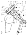
- a box roller 2 and a friction roller 4 are mounted in side walls 23 in the machine frame.
- a roller lever 17 is pinned to a shaft 1 and a forked lever 5 is pinned to the left and right between the side walls 23.
- a rocker arm 6 is mounted on the shaft 1. The arm of each rocker arm 6 is resiliently connected to the fork-shaped lever 5.
- a roller lever 17 with a cam roller 19 is pressed onto the cam of a cam plate 20 by means of a compression spring 21 via a spring rod 18.
- the compression spring 21 is supported on a spring support 22 mounted in the side walls 23. In this way it is ensured that when the cam disc 20 rotates, the shaft 1 performs an oscillating movement the size of a pivot angle 25.
- a jack roller 3 is received via roller bearings.
- adjustable resilient bolts 11, 12 having resilient buffers 7, 9, 11, 13; 8, 10, 12, 14 attached opposite each other.
- two adjusting screws 15, 16 arranged opposite one another are attached.
- a resilient friction ring 30, the diameter of which is selected to be slightly larger than the diameter of the lifting roller 3, is fastened on shaft sections 27 on both sides of the lifting roller 3 outside the ink-carrying contact points of the rollers 2, 3, 4.
- a hard friction ring 29 is fastened in the same way, the diameter of which is selected to be the same as the diameter of the box roller 2.
- a hard friction ring 31 is fastened in the same way on shaft sections 28 of the friction roller 4, the diameter of which is selected to be equal to the diameter of the friction roller 4.
- the friction rings 29 to 31 are so axially attached to the associated rollers 2, 3, 4 that the friction rings 29, 30 and 30, 31 of the approaching rollers 2, 3 and 3, 4 are able to roll on each other with mutual contact.
- the resilient friction rings 30 are made of a compressible material, e.g. made of rubber.
- the friction rings 29, 30 and 30, 31 first come into contact before the ink transfer is initiated.
- the time between the contact of the friction rings 29 to 31 and the ink transfer on the respective rollers 2, 3 and 3, 4 is used for speed compensation. This is achieved by the larger diameter and the compressibility of the friction rings 30 of the lifting roller.
- the compressibility is designed so that a perfect color transfer is guaranteed.
- the peripheral speed of the lifting roller 3 then corresponds to the peripheral speed of the box roller 2 or the friction roller 4.
Landscapes
- Inking, Control Or Cleaning Of Printing Machines (AREA)
- Rotary Presses (AREA)
Priority Applications (1)
| Application Number | Priority Date | Filing Date | Title |
|---|---|---|---|
| AT91101642T ATE104213T1 (de) | 1990-03-08 | 1991-02-07 | Antrieb einer heberwalze einer druckmaschine. |
Applications Claiming Priority (2)
| Application Number | Priority Date | Filing Date | Title |
|---|---|---|---|
| DE4007285 | 1990-03-08 | ||
| DE4007285A DE4007285C1 (enExample) | 1990-03-08 | 1990-03-08 |
Publications (2)
| Publication Number | Publication Date |
|---|---|
| EP0445542A1 EP0445542A1 (de) | 1991-09-11 |
| EP0445542B1 true EP0445542B1 (de) | 1994-04-13 |
Family
ID=6401675
Family Applications (1)
| Application Number | Title | Priority Date | Filing Date |
|---|---|---|---|
| EP91101642A Expired - Lifetime EP0445542B1 (de) | 1990-03-08 | 1991-02-07 | Antrieb einer Heberwalze einer Druckmaschine |
Country Status (4)
| Country | Link |
|---|---|
| EP (1) | EP0445542B1 (enExample) |
| AT (1) | ATE104213T1 (enExample) |
| DE (2) | DE4007285C1 (enExample) |
| ES (1) | ES2051530T3 (enExample) |
Cited By (1)
| Publication number | Priority date | Publication date | Assignee | Title |
|---|---|---|---|---|
| DE10158592A1 (de) * | 2001-11-29 | 2003-06-18 | Roland Man Druckmasch | Heberfarbwerk |
Family Cites Families (6)
| Publication number | Priority date | Publication date | Assignee | Title |
|---|---|---|---|---|
| DD121300A1 (enExample) * | 1975-05-23 | 1976-07-20 | ||
| DD141490A1 (de) * | 1979-03-01 | 1980-05-07 | Rudolf Stoerr | Heberantrieb |
| DD203016A1 (de) * | 1981-11-30 | 1983-10-12 | Hans Johne | Farbwerk fuer druckmaschinen |
| DD206350A1 (de) * | 1982-03-15 | 1984-01-25 | Guenter Schumann | Heberdosiersystem fuer druckmaschinen |
| DE3342877C1 (de) * | 1983-11-26 | 1985-01-10 | M.A.N.- Roland Druckmaschinen AG, 6050 Offenbach | Heberfarbwerk fuer eine Rotationsdruckmaschine |
| FR2564380B1 (fr) * | 1984-05-15 | 1990-06-15 | Marinoni Harris Sa | Dispositif de reduction de chocs dans la commande d'encrage d'un preneur d'encre alternatif de presse offset rotative |
-
1990
- 1990-03-08 DE DE4007285A patent/DE4007285C1/de not_active Expired - Lifetime
-
1991
- 1991-02-07 ES ES91101642T patent/ES2051530T3/es not_active Expired - Lifetime
- 1991-02-07 DE DE59101348T patent/DE59101348D1/de not_active Expired - Fee Related
- 1991-02-07 EP EP91101642A patent/EP0445542B1/de not_active Expired - Lifetime
- 1991-02-07 AT AT91101642T patent/ATE104213T1/de not_active IP Right Cessation
Cited By (2)
| Publication number | Priority date | Publication date | Assignee | Title |
|---|---|---|---|---|
| DE10158592A1 (de) * | 2001-11-29 | 2003-06-18 | Roland Man Druckmasch | Heberfarbwerk |
| DE10158592B4 (de) * | 2001-11-29 | 2006-03-23 | Man Roland Druckmaschinen Ag | Heberfarbwerk |
Also Published As
| Publication number | Publication date |
|---|---|
| DE4007285C1 (enExample) | 1991-06-06 |
| ATE104213T1 (de) | 1994-04-15 |
| DE59101348D1 (de) | 1994-05-19 |
| ES2051530T3 (es) | 1994-06-16 |
| EP0445542A1 (de) | 1991-09-11 |
Similar Documents
| Publication | Publication Date | Title |
|---|---|---|
| DE3243582C2 (de) | Vorrichtung zum Verändern des axialen Hubes einer Verreibwalze in einer Druckmaschine | |
| DE19940532B4 (de) | Druckmaschine mit einem Heberfarbwerk | |
| EP0796737B1 (de) | Reinigungseinrichtung an Rotationsdruckmaschinen | |
| EP0445542B1 (de) | Antrieb einer Heberwalze einer Druckmaschine | |
| EP0267504B1 (de) | Lagerung für changierende Auftragwalzen von Druckmaschinen | |
| DE3226814A1 (de) | Farbwerk fuer druckmaschinen | |
| DE10035354B4 (de) | Offsetdruckmaschine | |
| EP1088658B1 (de) | Kurzfarbwerk | |
| EP0475120A1 (de) | Hochgeschwindigkeitsfarbzufuhrmechanismus | |
| EP0179244B1 (de) | Vorrichtung zum Übertragen von Farbe in das Farbwerk von Druckmaschinen | |
| EP0480879A1 (de) | Vorrichtung zur stufenlosen Verstellung der axialen Verreibungsbewegung von Reibwalzen | |
| DE3836580C2 (enExample) | ||
| DE3621384A1 (de) | Vorrichtung zum antrieb eines schwingenden vorgreifers einer druckmaschine | |
| DE3241862C2 (enExample) | ||
| DE3402124C2 (enExample) | ||
| EP0467124B1 (de) | Schnell hin- und herbwegliche Hebwalze | |
| DE4141127A1 (de) | Farbheberantrieb fuer druckmaschinen | |
| DE4141126B4 (de) | Farbheberantrieb für Druckmaschinen | |
| EP0389740B1 (de) | Feuchtwerk | |
| DE232937C (enExample) | ||
| DE3625132C2 (enExample) | ||
| DE1436529C3 (enExample) | ||
| DE391303C (de) | Tiegeldruckpresse mit um den Mittelkoerper der Presse herumgefuehrten Auftragwalzen | |
| DE4017307A1 (de) | Heberfarbwerk fuer rotationsdruckmaschinen | |
| DE4140651C2 (de) | Feuchtauftragwalzenantrieb in Druckmaschinen |
Legal Events
| Date | Code | Title | Description |
|---|---|---|---|
| PUAI | Public reference made under article 153(3) epc to a published international application that has entered the european phase |
Free format text: ORIGINAL CODE: 0009012 |
|
| 17P | Request for examination filed |
Effective date: 19910711 |
|
| AK | Designated contracting states |
Kind code of ref document: A1 Designated state(s): AT BE CH DE ES FR GB IT LI NL SE |
|
| 17Q | First examination report despatched |
Effective date: 19930831 |
|
| ITF | It: translation for a ep patent filed | ||
| GRAA | (expected) grant |
Free format text: ORIGINAL CODE: 0009210 |
|
| AK | Designated contracting states |
Kind code of ref document: B1 Designated state(s): AT BE CH DE ES FR GB IT LI NL SE |
|
| REF | Corresponds to: |
Ref document number: 104213 Country of ref document: AT Date of ref document: 19940415 Kind code of ref document: T |
|
| ET | Fr: translation filed | ||
| REF | Corresponds to: |
Ref document number: 59101348 Country of ref document: DE Date of ref document: 19940519 |
|
| GBT | Gb: translation of ep patent filed (gb section 77(6)(a)/1977) |
Effective date: 19940503 |
|
| REG | Reference to a national code |
Ref country code: ES Ref legal event code: FG2A Ref document number: 2051530 Country of ref document: ES Kind code of ref document: T3 |
|
| EAL | Se: european patent in force in sweden |
Ref document number: 91101642.6 |
|
| PLBE | No opposition filed within time limit |
Free format text: ORIGINAL CODE: 0009261 |
|
| STAA | Information on the status of an ep patent application or granted ep patent |
Free format text: STATUS: NO OPPOSITION FILED WITHIN TIME LIMIT |
|
| 26N | No opposition filed | ||
| PGFP | Annual fee paid to national office [announced via postgrant information from national office to epo] |
Ref country code: GB Payment date: 19980112 Year of fee payment: 8 |
|
| PGFP | Annual fee paid to national office [announced via postgrant information from national office to epo] |
Ref country code: FR Payment date: 19980116 Year of fee payment: 8 Ref country code: BE Payment date: 19980116 Year of fee payment: 8 |
|
| PGFP | Annual fee paid to national office [announced via postgrant information from national office to epo] |
Ref country code: AT Payment date: 19980121 Year of fee payment: 8 |
|
| PGFP | Annual fee paid to national office [announced via postgrant information from national office to epo] |
Ref country code: SE Payment date: 19980126 Year of fee payment: 8 |
|
| PGFP | Annual fee paid to national office [announced via postgrant information from national office to epo] |
Ref country code: NL Payment date: 19980127 Year of fee payment: 8 |
|
| PGFP | Annual fee paid to national office [announced via postgrant information from national office to epo] |
Ref country code: CH Payment date: 19980203 Year of fee payment: 8 |
|
| PGFP | Annual fee paid to national office [announced via postgrant information from national office to epo] |
Ref country code: ES Payment date: 19980216 Year of fee payment: 8 |
|
| PG25 | Lapsed in a contracting state [announced via postgrant information from national office to epo] |
Ref country code: GB Free format text: LAPSE BECAUSE OF NON-PAYMENT OF DUE FEES Effective date: 19990207 Ref country code: AT Free format text: LAPSE BECAUSE OF NON-PAYMENT OF DUE FEES Effective date: 19990207 |
|
| PG25 | Lapsed in a contracting state [announced via postgrant information from national office to epo] |
Ref country code: SE Free format text: LAPSE BECAUSE OF NON-PAYMENT OF DUE FEES Effective date: 19990208 Ref country code: ES Free format text: LAPSE BECAUSE OF NON-PAYMENT OF DUE FEES Effective date: 19990208 |
|
| PG25 | Lapsed in a contracting state [announced via postgrant information from national office to epo] |
Ref country code: LI Free format text: LAPSE BECAUSE OF NON-PAYMENT OF DUE FEES Effective date: 19990228 Ref country code: CH Free format text: LAPSE BECAUSE OF NON-PAYMENT OF DUE FEES Effective date: 19990228 Ref country code: BE Free format text: LAPSE BECAUSE OF NON-PAYMENT OF DUE FEES Effective date: 19990228 |
|
| BERE | Be: lapsed |
Owner name: MAN ROLAND DRUCKMASCHINEN A.G. Effective date: 19990228 |
|
| PG25 | Lapsed in a contracting state [announced via postgrant information from national office to epo] |
Ref country code: NL Free format text: LAPSE BECAUSE OF NON-PAYMENT OF DUE FEES Effective date: 19990901 |
|
| GBPC | Gb: european patent ceased through non-payment of renewal fee |
Effective date: 19990207 |
|
| REG | Reference to a national code |
Ref country code: CH Ref legal event code: PL |
|
| PG25 | Lapsed in a contracting state [announced via postgrant information from national office to epo] |
Ref country code: FR Free format text: LAPSE BECAUSE OF NON-PAYMENT OF DUE FEES Effective date: 19991029 |
|
| EUG | Se: european patent has lapsed |
Ref document number: 91101642.6 |
|
| REG | Reference to a national code |
Ref country code: FR Ref legal event code: ST |
|
| REG | Reference to a national code |
Ref country code: ES Ref legal event code: FD2A Effective date: 20010503 |
|
| PGFP | Annual fee paid to national office [announced via postgrant information from national office to epo] |
Ref country code: DE Payment date: 20030208 Year of fee payment: 13 |
|
| PG25 | Lapsed in a contracting state [announced via postgrant information from national office to epo] |
Ref country code: DE Free format text: LAPSE BECAUSE OF NON-PAYMENT OF DUE FEES Effective date: 20040901 |
|
| PG25 | Lapsed in a contracting state [announced via postgrant information from national office to epo] |
Ref country code: IT Free format text: LAPSE BECAUSE OF NON-PAYMENT OF DUE FEES;WARNING: LAPSES OF ITALIAN PATENTS WITH EFFECTIVE DATE BEFORE 2007 MAY HAVE OCCURRED AT ANY TIME BEFORE 2007. THE CORRECT EFFECTIVE DATE MAY BE DIFFERENT FROM THE ONE RECORDED. Effective date: 20050207 |