EP0443433B1 - Couverture de façade - Google Patents
Couverture de façade Download PDFInfo
- Publication number
- EP0443433B1 EP0443433B1 EP91102069A EP91102069A EP0443433B1 EP 0443433 B1 EP0443433 B1 EP 0443433B1 EP 91102069 A EP91102069 A EP 91102069A EP 91102069 A EP91102069 A EP 91102069A EP 0443433 B1 EP0443433 B1 EP 0443433B1
- Authority
- EP
- European Patent Office
- Prior art keywords
- catch
- webs
- bend
- edge
- façade
- Prior art date
- Legal status (The legal status is an assumption and is not a legal conclusion. Google has not performed a legal analysis and makes no representation as to the accuracy of the status listed.)
- Expired - Lifetime
Links
Images

Classifications
-
- E—FIXED CONSTRUCTIONS
- E04—BUILDING
- E04F—FINISHING WORK ON BUILDINGS, e.g. STAIRS, FLOORS
- E04F13/00—Coverings or linings, e.g. for walls or ceilings
- E04F13/07—Coverings or linings, e.g. for walls or ceilings composed of covering or lining elements; Sub-structures therefor; Fastening means therefor
- E04F13/08—Coverings or linings, e.g. for walls or ceilings composed of covering or lining elements; Sub-structures therefor; Fastening means therefor composed of a plurality of similar covering or lining elements
- E04F13/0801—Separate fastening elements
- E04F13/0803—Separate fastening elements with load-supporting elongated furring elements between wall and covering elements
- E04F13/081—Separate fastening elements with load-supporting elongated furring elements between wall and covering elements with additional fastening elements between furring elements and covering elements
Definitions
- the invention relates to a facade cladding according to the preamble of claim 1.
- Facade cladding in which the edge folds are essentially formed by bevels angled perpendicularly in the direction of the substructure, the latching recesses for hanging on bolts arranged parallel to the building wall to be clad and connected to the substructure.
- These bolts are arranged between the legs of a U-shaped mounting rail at a vertical distance of approximately 80 cm from one another.
- Such a mounting rail can serve to hold two horizontally abutting wall elements on their mutually opposite vertical abutting edges. The bolts are then disadvantageously visible between the adjoining wall elements.
- These known facade claddings also have defects in terms of dimensional stability.
- a facade cladding of the type mentioned has become known. It has cassette-like cladding elements which comprise a cassette floor and at least on mutually opposite, vertically running edges in the direction of a substructure from the cassette floor, angled edge folds, with spaced-apart latching devices in the vertically running lateral edge regions of the cladding elements for hanging the cladding elements into corresponding ones , holding devices attached to the substructure are provided.
- the jack consoles have slots for Kirkstegen's intervention.
- sheet metal supports are fastened to the first bending portions and run parallel to the cassette bottom, which are T-shaped and have a transverse web for fastening to the first bending and a longitudinal web which runs parallel to the cassette bottom.
- the latch brackets with the slots are inserted into U-shaped recesses in the legs of the U-shaped mounting rails, which are fastened vertically to the wall, the brackets being fastened therein by means of screws.
- a facade cladding which can be attached to a building wall and in which the cladding elements have a first fold perpendicular to the cassette floor and a second fold which runs parallel to the cassette floor has become known from DE 37 33 359 A.
- the latch brackets with the slots are clamped in hollow profiles on a support rail that runs true to normal, whereby exact locking is not possible.
- a kit consisting of individual construction elements for wall or ceiling cladding on buildings has become known.
- a first U-shaped mounting rail is provided, which is fastened perpendicularly to the building wall;
- a hat-profile-like mounting rail is attached, which partially engages inside the two legs of the mounting rail, and hooks are provided on the L-shaped bevels of the hat-profile-like mounting rail, into which the panel elements are hung, with closed slots provided in the second bend are that can be slid over the slots and only then hooked in.
- a shaped piece is provided (see DE-U-8621 152, Fig. 22), which is designed as a plastic clip and has a shape which is adapted to the complicated shape of the jack brackets with slot.
- the object of the invention is to provide a facade cladding of the type mentioned, which is simplified compared to the facade cladding known from AT-B-385 305.
- a rastering of the latching brackets and the latching webs should be provided, which is predetermined by the construction of the facade cladding.
- the vertical edge bend includes a first edge bend angled from the cassette bottom and a second edge bend angled from the first edge bend means a considerable simplification, in particular compared to the construction according to AT-B-385 305.
- a clear latching is possible and any subsequent adjustments on the construction site, such as are required for the design according to AT-B 385 305, are no longer necessary with the facade cladding according to the invention.
- the cladding elements are given a high degree of connection stability, which is advantageous not only in terms of the dimensional stability of the cladding elements in the assembled state, but also in terms of stresses when transporting the connecting elements from the manufacturing site to the construction site.
- the mounting rail profile can advantageously be prefabricated in a standard length with the jack brackets in the specific grid spacing, so that no measures for project-related are carried out on the construction site or during prefabrication Attachment of support elements to the substructure may be required.
- a sorting of the mounting rails on the construction site can be omitted, since all rails have the same grid dimension in relation to the latching brackets and are not attached to the mounting rail bolts in a project-specific manner as in the known arrangements.
- DIN rail profiles in a standard length result in further advantages with regard to the pretreatments, such as the application of a coating which improves the appearance and possibly protects against corrosion, with a device tailored to this standard length, the transport to the construction site and storage. Residual rails may only be used after repainting on any other construction site.
- clamping devices are provided which can be pushed onto the latching webs, wherein they have the shape of a spring clip and are held resiliently on the latching webs.
- the latch bars are clamped in the slots of the latch brackets, so that the latch bars are immobilized within the slots, so that e.g. rattling noises cannot occur when the facade cladding is exposed to wind.
- metallic clips an electrical connection is made between the cladding elements and the substructure, so that only a common grounding line is required for grounding the facade cladding, in contrast to, for example, the design according to DE-U-8621 152, in which plastic caps are provided , which provide electrical insulation of the cladding elements from the substructure.
- a recess is provided according to claim 5.
- a stop lug can be provided which serves on the one hand to guide the spring clip and on the other hand as a stop against the latch bracket.
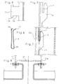
- reference number 1 denotes a cassette-shaped cladding element which has a cassette base 2 and a bevel 3 or 3a on opposite, vertically extending edges.
- the bevels 3 and 3a comprise a first bevel 8 or 8a perpendicular to the cassette base 2 and a second bevel which is angled inwards from the perpendicular bevel 8 or 8a with respect to the surface of the cassette base and runs parallel to the surface of the cassette base 2 9 or 9a. From the folds 9 and 9a, latch webs 5 and 5a, respectively, are formed as latch tabs 5 and 5a.
- the cladding element 1 further comprises on its upper edge a bevel 4, a first bevel 11 perpendicular to the cassette bottom 2 and one second, bent from the bend 11 upward bend 10 comprises.
- the fold 11 has a greater length than the fold 12.
- the distance between the latches 5 and 5a from the cassette bottom is approximately 50 mm.
- the foothills of the mounting rail profiles are designated.
- These support rail profiles which serve as a substructure, are connected to the wall to be clad via a leg 17 or 17a, while a leg perpendicular to the leg 17 or 17a has latching brackets 6 at a certain grid spacing, in the present example at a distance of 10 cm, which are integrally formed with this leg.
- a latch 5 in which a latch 5 is shown separately, 14 denotes a recess delimited by a nose 15, which forms a seat for the spring clip 16, which is shown separately in Fig. 6 and which corresponds to this recess Width, and as can be seen in FIG. 6, has bends 18 and 19 at its upper end.
- FIG. 5 which separately shows a latch bracket 6, 7 denotes a slot for the engagement of a latch bracket 5.
- the cladding elements 1 with the latches 5 are hooked into the slots 7 of the latching brackets 6, each latching bracket of the mounting rail profile 13 or 13a being used in the present exemplary embodiment.
- the raster width of the latch tabs is 10 cm.
- the suspension path in the direction of the wall is 15 mm in the present exemplary embodiment. With a construction depth of 60 mm, there is no need to click the substructure for the horizontal facade joints.
- FIG. 8 in which an embodiment of a joint between two horizontally adjacent cladding elements is shown, 13 'is an expediently designed as an H-profile support rail, whose side legs 17 and 17a are provided with latch brackets according to FIG. 5. Due to this advantageous design of the mounting rail profile as an H-profile, only one mounting rail is required for the horizontal connection of two horizontally adjacent plates.
- FIG. 7 shows how the spring clip 16 clamps the tab 5 in the slot 7.
- the clip can be used to create a non-positive connection between the latch and the bracket. Since the spring clip corresponds in width to the recess 14 in the latch 5, a seat for the latch is formed by the recess 14, so that the spring clip, which is longer than the latch after it has been pushed onto the latch, neither in can be stripped more vertically or in the horizontal direction from the latch clip without the application of force by the bend 18 and the nose 15 each forming a vertical or horizontal stop.
- the nose 15 prevents the latch clip provided with the spring clip from slipping out of the slot in the latch bracket during lateral displacement. Because the spring clip is made of metal, an electrical connection is made from the cladding elements to the substructure, so that advantageously only a single grounding line is required for the entire wall cladding.
- the narrow grid of the suspension points helps to prevent deformation of the cladding elements that impair the appearance of the facade cladding.
- the fact that the edge of the cassette bottoms is folded in a C-shape on the vertical sides results in a high torsional rigidity of the cassette-like cladding elements, so that deformations of these during transport can be largely avoided.
- the tight grid of the latches or the latch brackets makes a project-related calculation of the suspension points of the cladding elements unnecessary. Time-consuming work for the project-related prefabrication of the cladding elements and mounting rails is eliminated. For length information that must be communicated to the assembly staff for the work on site, you can largely rely on the grid dimensions.
- the mounting rails can advantageously be manufactured in standard lengths.
- the support rails manufactured in standard lengths also have advantages in terms of pretreatment, e.g. the application of a coating in that the parts of the same length can be pre-processed in a treatment device tailored for this purpose. Since the mounting rails can be delivered to the construction site in a standard length, there are also advantages in terms of warehousing. Residual rails may only be reused on any other construction site after repainting. Fastening elements need not be attached to the elements either before or after the coating. This eliminates the risk of crevice corrosion due to chrome plating residues and there is no need to subsequently coat fasteners.
Landscapes
- Engineering & Computer Science (AREA)
- Architecture (AREA)
- Civil Engineering (AREA)
- Structural Engineering (AREA)
- Finishing Walls (AREA)
Claims (7)
- Bardage de façade à éléments de bardage du type caisson (1), qui comprennent un corps de caisson (2) et des chanfreins (3,3a;4;4a), inclinés depuis le corps du caisson en direction d'une sous-structure, réalisés au moins aux bords se faisant face et s'étendant verticalement, des dispositifs de clavetage disposés latéralement à une certaine distance les uns des autres au voisinage des bords latéraux, s'étendant verticalement, des élements de bardage étant prévus pour l'accrochage des éléments de bardage (1) dans les dispositifs d'ancrage correspondants prévus dans la sous-structure, les dispositifs de clavetage étant formés d'entretoises de clavetage (5) qui sont prévues aux chanfreins, qui s'étendent à distance du corps du caisson (2) et essentiellement parallèlement à ce dernier et qui font saillie par rapport au chanfrein et les dispositifs d'ancrage étant formés de consoles de clavetage (6) qui sont prévues sur des rails de support qui s'étendent essentiellement dans la direction verticale avec des fentes de couplage (7) pour l'engagement des entretoises (5), caractérisé en ce que chaque chanfrein vertical (3,3a) comprend un premier biseau (8, 8a), incline par rapport au corps du caisson et un deuxième biseau (9,9a) incliné par rapport au premier biseau, en ce que les entretoises de clavetage (5) du deuxième biseau (9,9a) font saillie sur le chanfrein (3,3a), en ce que les entretoises de clavetage (5) sont maintenues élastiquement dans les fentes de couplage (7) des consoles de clavetage (6) par un dispositif de serrage formé d'une clavette-ressort (16) essentiellement en forme de U, qui se laisse glisser sur l'entretoise de clavetage, et en ce que les consoles de clavetage sont disposées à la même hauteur à une distance de quadrillage sur la façade.
- Bardage de façade selon la revendication 1, caractérisé en ce que la distance de quadrillage est d'environ 0,1 m.
- Bardage selon l'une des revendications 1 ou 2, caractérisé en ce que les entretoises de clavetage (5) en place sur les bords des éléments de bardage (1) se faisant face et s'étendant verticalement sont disposées face à face à la même hauteur.
- Bardage de façade selon l'une quelconque des revendications 1 à 4, caractérisé en ce que les rails de support munis de consoles de clavetage (6) sont essentiellement faits de profils en forme de U ou de H.
- Bardage de façade selon l'une quelconque des revendications 1 à 4, caractérisé en ce que les entretoises de clavetage (5) ont, à leur bord inférieur, un évidement (14) formant appui pour l'extrémité fermée de la clavette (16) en forme de U.
- Bardage de façade selon l'une quelconque des revendications 1 à 5, caractérisé en ce que les entretoises de clavetage ont, à leur bord inférieur, une extrémité butoiré pour l'arrêt contre les consoles de clavetage (6).
- Bardage selon l'une quelconque des revendications 1 à 6, caractérisé en ce que les entretoises de clavetage (5) sont disposées le long du biseau à une distance de quadrillage qui est égale ou multiple de la distance de quadrillage des consoles de clavetage (6).
Priority Applications (1)
| Application Number | Priority Date | Filing Date | Title |
|---|---|---|---|
| AT91102069T ATE81700T1 (de) | 1990-02-21 | 1991-02-14 | Fassadenverkleidung. |
Applications Claiming Priority (2)
| Application Number | Priority Date | Filing Date | Title |
|---|---|---|---|
| DE4005508A DE4005508C2 (de) | 1990-02-21 | 1990-02-21 | Fassadenverkleidung |
| DE4005508 | 1990-02-21 |
Publications (2)
| Publication Number | Publication Date |
|---|---|
| EP0443433A1 EP0443433A1 (fr) | 1991-08-28 |
| EP0443433B1 true EP0443433B1 (fr) | 1992-10-21 |
Family
ID=6400683
Family Applications (1)
| Application Number | Title | Priority Date | Filing Date |
|---|---|---|---|
| EP91102069A Expired - Lifetime EP0443433B1 (fr) | 1990-02-21 | 1991-02-14 | Couverture de façade |
Country Status (3)
| Country | Link |
|---|---|
| EP (1) | EP0443433B1 (fr) |
| AT (1) | ATE81700T1 (fr) |
| DE (1) | DE4005508C2 (fr) |
Families Citing this family (3)
| Publication number | Priority date | Publication date | Assignee | Title |
|---|---|---|---|---|
| FR2697298B1 (fr) * | 1992-10-28 | 1995-01-13 | Profilor Sa | Structure de raccordement et d'assemblage de pièces de revêtement constituant un habillage extérieur par rapport à un support donné. |
| DE4421614C2 (de) * | 1994-06-21 | 2000-01-05 | Sommer Metallbau Stahlbau Gmbh | Fassadenverkleidung |
| US5575124A (en) * | 1995-03-29 | 1996-11-19 | Novello, Jr.; Eligio | Construction with modular walls |
Family Cites Families (5)
| Publication number | Priority date | Publication date | Assignee | Title |
|---|---|---|---|---|
| DE3517443A1 (de) * | 1985-05-14 | 1986-11-20 | Straub GmbH & Co Metallbau, 8857 Wertingen | Haltekonstruktion fuer hinterlueftete fassaden aus schalenfoermigen fassadenelementen |
| GB2188075B (en) * | 1986-03-12 | 1989-12-06 | Crittall Windows Ltd | Building cladding |
| AT385305B (de) * | 1986-06-02 | 1988-03-25 | Bug Alutechnik | Profilleiste zur befestigung von fassadenelementen |
| DE8621152U1 (de) * | 1986-08-07 | 1987-12-03 | Christian Pohl GmbH, 5000 Köln | Aus einzelnen Konstruktionselementen bestehender Bausatz für Wand- oder Deckenbekleidungen an Bauwerken |
| DE3733359A1 (de) * | 1987-10-02 | 1989-04-13 | Hupfeld & Schloeffel Metallbau | An einer gebaeudewand anbringbare fassade |
-
1990
- 1990-02-21 DE DE4005508A patent/DE4005508C2/de not_active Expired - Fee Related
-
1991
- 1991-02-14 EP EP91102069A patent/EP0443433B1/fr not_active Expired - Lifetime
- 1991-02-14 AT AT91102069T patent/ATE81700T1/de not_active IP Right Cessation
Also Published As
| Publication number | Publication date |
|---|---|
| DE4005508A1 (de) | 1991-08-22 |
| EP0443433A1 (fr) | 1991-08-28 |
| ATE81700T1 (de) | 1992-11-15 |
| DE4005508C2 (de) | 2001-08-16 |
Similar Documents
| Publication | Publication Date | Title |
|---|---|---|
| DE60216008T2 (de) | Schienenvorrichtung zum Tragen von Wandpfosten, Verfahren und Wandrahmenanordnung | |
| DE2945148C2 (de) | Vorrichtung zum Befestigen von Wärmedämmplatten am Rahmen eines Fensters | |
| DE3139829A1 (de) | Pfosten fuer eine demontierbare trennwand | |
| EP0180837B2 (fr) | Jeu de pièces séparées pour un dispositif de fixation de murs rideaux | |
| DE3726255A1 (de) | Trennwand | |
| EP3548412A2 (fr) | Dispositif de fixation et procédé permettant de fixer un élément de paroi dans une cabine d'ascenseur | |
| DE2610998C3 (de) | Halterung zur Befestigung von Bekleidungsplatten vor einer Bauwerkswand | |
| EP3222794B1 (fr) | Dispositif de retenue destine a appliquer des elements de revetement de plafond ou mural en forme de plaques sur un fond cote construction et procede de fabrication du dispositif de retenue | |
| EP0443433B1 (fr) | Couverture de façade | |
| DE102017101509A1 (de) | Konsole zur Befestigung von Fassadenelementen | |
| DE2927164A1 (de) | Fassadenverkleidung | |
| DE20214938U1 (de) | Fassadensystem aus keramischen Fassadenplatten zum Einsatz als vorgehängte hinterlüftete Fassade an einer tragenden Bauwerkswand | |
| EP0010694B1 (fr) | Revêtement pour murs ou plafonds | |
| DE20200530U1 (de) | Unterkonstruktion für eine Wandbekleidung von Bauwerken mit Wandbekleidungsplatten aus einem massiven Werkstoff | |
| AT1026U1 (de) | Profilschiene | |
| DE3245851A1 (de) | Gelaender | |
| DE2606726C2 (de) | Nichttragende Wandkonstruktion | |
| DE8417333U1 (de) | Abhaenge-vorrichtung fuer c-foermige tragschienen von unterdecken od. dgl. | |
| EP0639680B1 (fr) | Suspente pour plafonds suspendus | |
| DE20114555U1 (de) | Ankerwinkel | |
| DE9102531U1 (de) | Deckenverkleidung | |
| DE19932528C1 (de) | Montagehilfe eines Trag-, Anschluß- oder Abschlußprofils für einen Dämmstoff | |
| DE2103993A1 (de) | Verkleidung für Klima-Induktionsgeräte und Konrektoren | |
| DE19625315A1 (de) | Wandsystem | |
| DE20105400U1 (de) | Montagehilfsvorrichtung zur Befestigung einer Unterkonstruktion zwecks Aufnahme von Wand- oder Deckenverkleidungen |
Legal Events
| Date | Code | Title | Description |
|---|---|---|---|
| PUAI | Public reference made under article 153(3) epc to a published international application that has entered the european phase |
Free format text: ORIGINAL CODE: 0009012 |
|
| 17P | Request for examination filed |
Effective date: 19910214 |
|
| AK | Designated contracting states |
Kind code of ref document: A1 Designated state(s): AT CH FR GB LI |
|
| 17Q | First examination report despatched |
Effective date: 19911029 |
|
| GRAA | (expected) grant |
Free format text: ORIGINAL CODE: 0009210 |
|
| AK | Designated contracting states |
Kind code of ref document: B1 Designated state(s): AT CH FR GB LI |
|
| REF | Corresponds to: |
Ref document number: 81700 Country of ref document: AT Date of ref document: 19921115 Kind code of ref document: T |
|
| ET | Fr: translation filed | ||
| GBT | Gb: translation of ep patent filed (gb section 77(6)(a)/1977) |
Effective date: 19930127 |
|
| PLBE | No opposition filed within time limit |
Free format text: ORIGINAL CODE: 0009261 |
|
| STAA | Information on the status of an ep patent application or granted ep patent |
Free format text: STATUS: NO OPPOSITION FILED WITHIN TIME LIMIT |
|
| 26N | No opposition filed | ||
| PGFP | Annual fee paid to national office [announced via postgrant information from national office to epo] |
Ref country code: CH Payment date: 19940118 Year of fee payment: 4 |
|
| PGFP | Annual fee paid to national office [announced via postgrant information from national office to epo] |
Ref country code: FR Payment date: 19940121 Year of fee payment: 4 |
|
| PGFP | Annual fee paid to national office [announced via postgrant information from national office to epo] |
Ref country code: AT Payment date: 19940214 Year of fee payment: 4 |
|
| PG25 | Lapsed in a contracting state [announced via postgrant information from national office to epo] |
Ref country code: GB Effective date: 19950214 Ref country code: AT Effective date: 19950214 |
|
| PG25 | Lapsed in a contracting state [announced via postgrant information from national office to epo] |
Ref country code: LI Effective date: 19950228 Ref country code: CH Effective date: 19950228 |
|
| GBPC | Gb: european patent ceased through non-payment of renewal fee |
Effective date: 19950214 |
|
| PG25 | Lapsed in a contracting state [announced via postgrant information from national office to epo] |
Ref country code: FR Effective date: 19951031 |
|
| REG | Reference to a national code |
Ref country code: FR Ref legal event code: ST |