EP0443433B1 - Façade covering - Google Patents
Façade covering Download PDFInfo
- Publication number
- EP0443433B1 EP0443433B1 EP91102069A EP91102069A EP0443433B1 EP 0443433 B1 EP0443433 B1 EP 0443433B1 EP 91102069 A EP91102069 A EP 91102069A EP 91102069 A EP91102069 A EP 91102069A EP 0443433 B1 EP0443433 B1 EP 0443433B1
- Authority
- EP
- European Patent Office
- Prior art keywords
- catch
- webs
- bend
- edge
- façade
- Prior art date
- Legal status (The legal status is an assumption and is not a legal conclusion. Google has not performed a legal analysis and makes no representation as to the accuracy of the status listed.)
- Expired - Lifetime
Links
Images

Classifications
-
- E—FIXED CONSTRUCTIONS
- E04—BUILDING
- E04F—FINISHING WORK ON BUILDINGS, e.g. STAIRS, FLOORS
- E04F13/00—Coverings or linings, e.g. for walls or ceilings
- E04F13/07—Coverings or linings, e.g. for walls or ceilings composed of covering or lining elements; Sub-structures therefor; Fastening means therefor
- E04F13/08—Coverings or linings, e.g. for walls or ceilings composed of covering or lining elements; Sub-structures therefor; Fastening means therefor composed of a plurality of similar covering or lining elements
- E04F13/0801—Separate fastening elements
- E04F13/0803—Separate fastening elements with load-supporting elongated furring elements between wall and covering elements
- E04F13/081—Separate fastening elements with load-supporting elongated furring elements between wall and covering elements with additional fastening elements between furring elements and covering elements
Definitions
- the invention relates to a facade cladding according to the preamble of claim 1.
- Facade cladding in which the edge folds are essentially formed by bevels angled perpendicularly in the direction of the substructure, the latching recesses for hanging on bolts arranged parallel to the building wall to be clad and connected to the substructure.
- These bolts are arranged between the legs of a U-shaped mounting rail at a vertical distance of approximately 80 cm from one another.
- Such a mounting rail can serve to hold two horizontally abutting wall elements on their mutually opposite vertical abutting edges. The bolts are then disadvantageously visible between the adjoining wall elements.
- These known facade claddings also have defects in terms of dimensional stability.
- a facade cladding of the type mentioned has become known. It has cassette-like cladding elements which comprise a cassette floor and at least on mutually opposite, vertically running edges in the direction of a substructure from the cassette floor, angled edge folds, with spaced-apart latching devices in the vertically running lateral edge regions of the cladding elements for hanging the cladding elements into corresponding ones , holding devices attached to the substructure are provided.
- the jack consoles have slots for Kirkstegen's intervention.
- sheet metal supports are fastened to the first bending portions and run parallel to the cassette bottom, which are T-shaped and have a transverse web for fastening to the first bending and a longitudinal web which runs parallel to the cassette bottom.
- the latch brackets with the slots are inserted into U-shaped recesses in the legs of the U-shaped mounting rails, which are fastened vertically to the wall, the brackets being fastened therein by means of screws.
- a facade cladding which can be attached to a building wall and in which the cladding elements have a first fold perpendicular to the cassette floor and a second fold which runs parallel to the cassette floor has become known from DE 37 33 359 A.
- the latch brackets with the slots are clamped in hollow profiles on a support rail that runs true to normal, whereby exact locking is not possible.
- a kit consisting of individual construction elements for wall or ceiling cladding on buildings has become known.
- a first U-shaped mounting rail is provided, which is fastened perpendicularly to the building wall;
- a hat-profile-like mounting rail is attached, which partially engages inside the two legs of the mounting rail, and hooks are provided on the L-shaped bevels of the hat-profile-like mounting rail, into which the panel elements are hung, with closed slots provided in the second bend are that can be slid over the slots and only then hooked in.
- a shaped piece is provided (see DE-U-8621 152, Fig. 22), which is designed as a plastic clip and has a shape which is adapted to the complicated shape of the jack brackets with slot.
- the object of the invention is to provide a facade cladding of the type mentioned, which is simplified compared to the facade cladding known from AT-B-385 305.
- a rastering of the latching brackets and the latching webs should be provided, which is predetermined by the construction of the facade cladding.
- the vertical edge bend includes a first edge bend angled from the cassette bottom and a second edge bend angled from the first edge bend means a considerable simplification, in particular compared to the construction according to AT-B-385 305.
- a clear latching is possible and any subsequent adjustments on the construction site, such as are required for the design according to AT-B 385 305, are no longer necessary with the facade cladding according to the invention.
- the cladding elements are given a high degree of connection stability, which is advantageous not only in terms of the dimensional stability of the cladding elements in the assembled state, but also in terms of stresses when transporting the connecting elements from the manufacturing site to the construction site.
- the mounting rail profile can advantageously be prefabricated in a standard length with the jack brackets in the specific grid spacing, so that no measures for project-related are carried out on the construction site or during prefabrication Attachment of support elements to the substructure may be required.
- a sorting of the mounting rails on the construction site can be omitted, since all rails have the same grid dimension in relation to the latching brackets and are not attached to the mounting rail bolts in a project-specific manner as in the known arrangements.
- DIN rail profiles in a standard length result in further advantages with regard to the pretreatments, such as the application of a coating which improves the appearance and possibly protects against corrosion, with a device tailored to this standard length, the transport to the construction site and storage. Residual rails may only be used after repainting on any other construction site.
- clamping devices are provided which can be pushed onto the latching webs, wherein they have the shape of a spring clip and are held resiliently on the latching webs.
- the latch bars are clamped in the slots of the latch brackets, so that the latch bars are immobilized within the slots, so that e.g. rattling noises cannot occur when the facade cladding is exposed to wind.
- metallic clips an electrical connection is made between the cladding elements and the substructure, so that only a common grounding line is required for grounding the facade cladding, in contrast to, for example, the design according to DE-U-8621 152, in which plastic caps are provided , which provide electrical insulation of the cladding elements from the substructure.
- a recess is provided according to claim 5.
- a stop lug can be provided which serves on the one hand to guide the spring clip and on the other hand as a stop against the latch bracket.
- reference number 1 denotes a cassette-shaped cladding element which has a cassette base 2 and a bevel 3 or 3a on opposite, vertically extending edges.
- the bevels 3 and 3a comprise a first bevel 8 or 8a perpendicular to the cassette base 2 and a second bevel which is angled inwards from the perpendicular bevel 8 or 8a with respect to the surface of the cassette base and runs parallel to the surface of the cassette base 2 9 or 9a. From the folds 9 and 9a, latch webs 5 and 5a, respectively, are formed as latch tabs 5 and 5a.
- the cladding element 1 further comprises on its upper edge a bevel 4, a first bevel 11 perpendicular to the cassette bottom 2 and one second, bent from the bend 11 upward bend 10 comprises.
- the fold 11 has a greater length than the fold 12.
- the distance between the latches 5 and 5a from the cassette bottom is approximately 50 mm.
- the foothills of the mounting rail profiles are designated.
- These support rail profiles which serve as a substructure, are connected to the wall to be clad via a leg 17 or 17a, while a leg perpendicular to the leg 17 or 17a has latching brackets 6 at a certain grid spacing, in the present example at a distance of 10 cm, which are integrally formed with this leg.
- a latch 5 in which a latch 5 is shown separately, 14 denotes a recess delimited by a nose 15, which forms a seat for the spring clip 16, which is shown separately in Fig. 6 and which corresponds to this recess Width, and as can be seen in FIG. 6, has bends 18 and 19 at its upper end.
- FIG. 5 which separately shows a latch bracket 6, 7 denotes a slot for the engagement of a latch bracket 5.
- the cladding elements 1 with the latches 5 are hooked into the slots 7 of the latching brackets 6, each latching bracket of the mounting rail profile 13 or 13a being used in the present exemplary embodiment.
- the raster width of the latch tabs is 10 cm.
- the suspension path in the direction of the wall is 15 mm in the present exemplary embodiment. With a construction depth of 60 mm, there is no need to click the substructure for the horizontal facade joints.
- FIG. 8 in which an embodiment of a joint between two horizontally adjacent cladding elements is shown, 13 'is an expediently designed as an H-profile support rail, whose side legs 17 and 17a are provided with latch brackets according to FIG. 5. Due to this advantageous design of the mounting rail profile as an H-profile, only one mounting rail is required for the horizontal connection of two horizontally adjacent plates.
- FIG. 7 shows how the spring clip 16 clamps the tab 5 in the slot 7.
- the clip can be used to create a non-positive connection between the latch and the bracket. Since the spring clip corresponds in width to the recess 14 in the latch 5, a seat for the latch is formed by the recess 14, so that the spring clip, which is longer than the latch after it has been pushed onto the latch, neither in can be stripped more vertically or in the horizontal direction from the latch clip without the application of force by the bend 18 and the nose 15 each forming a vertical or horizontal stop.
- the nose 15 prevents the latch clip provided with the spring clip from slipping out of the slot in the latch bracket during lateral displacement. Because the spring clip is made of metal, an electrical connection is made from the cladding elements to the substructure, so that advantageously only a single grounding line is required for the entire wall cladding.
- the narrow grid of the suspension points helps to prevent deformation of the cladding elements that impair the appearance of the facade cladding.
- the fact that the edge of the cassette bottoms is folded in a C-shape on the vertical sides results in a high torsional rigidity of the cassette-like cladding elements, so that deformations of these during transport can be largely avoided.
- the tight grid of the latches or the latch brackets makes a project-related calculation of the suspension points of the cladding elements unnecessary. Time-consuming work for the project-related prefabrication of the cladding elements and mounting rails is eliminated. For length information that must be communicated to the assembly staff for the work on site, you can largely rely on the grid dimensions.
- the mounting rails can advantageously be manufactured in standard lengths.
- the support rails manufactured in standard lengths also have advantages in terms of pretreatment, e.g. the application of a coating in that the parts of the same length can be pre-processed in a treatment device tailored for this purpose. Since the mounting rails can be delivered to the construction site in a standard length, there are also advantages in terms of warehousing. Residual rails may only be reused on any other construction site after repainting. Fastening elements need not be attached to the elements either before or after the coating. This eliminates the risk of crevice corrosion due to chrome plating residues and there is no need to subsequently coat fasteners.
Landscapes
- Engineering & Computer Science (AREA)
- Architecture (AREA)
- Civil Engineering (AREA)
- Structural Engineering (AREA)
- Finishing Walls (AREA)
Abstract
Description
Die Erfindung betrifft eine Fassadenverkleidung gemäß dem Oberbegriff des Anspruches 1.The invention relates to a facade cladding according to the preamble of
Es sind Fassadenverkleidungen bekannt, bei denen die Randabkantungen im wesentlichen durch in Richtung auf die Unterkonstruktion senkrecht abgewinkelte Abkantungen gebildet sind, die Klinkausnehmungen zum Einhängen auf parallel zu der zu verkleidenden Gebäudewand angeordneten, mit der Unterkonstruktion verbunden Bolzen aufweisen. Diese Bolzen sind zwischen den Schenkeln einer U-förmigen Tragschiene im vertikalen Abstand von ca. 80 cm zueinander angeordnet. Eine solche Tragschiene kann zur Halterung von jeweils zwei horizontal aneinanderstoßenden Wandelementen an deren einander gegenüberliegenden vertikalen Stoßrändern dienen. Unvorteilhaft sind die Bolzen dann zwischen den aneinandergrenzenden Wandelementen sichtbar. Auch in Bezug auf die Formbeständigkeit weisen diese bekannten Fassadenverkleidungen Mängel auf.Facade cladding is known in which the edge folds are essentially formed by bevels angled perpendicularly in the direction of the substructure, the latching recesses for hanging on bolts arranged parallel to the building wall to be clad and connected to the substructure. These bolts are arranged between the legs of a U-shaped mounting rail at a vertical distance of approximately 80 cm from one another. Such a mounting rail can serve to hold two horizontally abutting wall elements on their mutually opposite vertical abutting edges. The bolts are then disadvantageously visible between the adjoining wall elements. These known facade claddings also have defects in terms of dimensional stability.
Aus der AT-B-385 305 ist eine Fassadenverkleidung der eingangs genannten Art bekannt geworden. Sie besitzt kassettenartige Verkleidungselemente, die einen Kassettenboden und wenigstens an einander gegenüberliegenden, vertikal verlaufend vorgesehenen Rändern in Richtung auf eine Unterkonstruktion vom Kassettenboden aus abgewinkelte Randabkantungen umfassen, wobei in den vertikal verlaufenden seitlichen Randbereichen der Verkleidungselemente in Abstand zueinander angeordnete Klinkeinrichtungen zum Einhängen der Verkleidungselemente in entsprechende, an der Unterkonstruktion angebrachte Halteinrichtungen vorgesehen sind. Die Klinkkonsolen besitzen Einschlitzungen für den Eingriff von Kirkstegen. Zur Bildung dieser Klinkstege sind an den ersten Abkantmgen parallel zu dem Kassettenboden verlaufende Blechauflager befestigt, welche T-förmig ausgebildet sind und einen Quersteg zur Befestigung an der ersten Abkantung und einen Längssteg aufweisen, der parallel zum Kassettenboden verläuft. Die Klinkkonsolen mit den Einschlitzungen sind in U-förmigen Ausnehmungen der Schenkel der U-förmigen, senkrecht an der Wand befestigten Tragschienen eingesetzt, wobei die Konsolen darin mittels Schrauben befestigt sind.From AT-B-385 305 a facade cladding of the type mentioned has become known. It has cassette-like cladding elements which comprise a cassette floor and at least on mutually opposite, vertically running edges in the direction of a substructure from the cassette floor, angled edge folds, with spaced-apart latching devices in the vertically running lateral edge regions of the cladding elements for hanging the cladding elements into corresponding ones , holding devices attached to the substructure are provided. The jack consoles have slots for Kirkstegen's intervention. To form these latching webs, sheet metal supports are fastened to the first bending portions and run parallel to the cassette bottom, which are T-shaped and have a transverse web for fastening to the first bending and a longitudinal web which runs parallel to the cassette bottom. The latch brackets with the slots are inserted into U-shaped recesses in the legs of the U-shaped mounting rails, which are fastened vertically to the wall, the brackets being fastened therein by means of screws.
Eine an einer Gebäudewand anbringbare Fassadenverkleidung, bei der die Verkleidungselemente eine erste Abkantung senkrecht zum Kassettenboden und eine zweite Abkantung, die parallel zum Kassettenboden verläuft, aufweisen, ist aus der DE- 37 33 359 A bekannt geworden. Die Klinkkonsolen mit den Einschlitzungen sind in Hohlprofilen an einer senrkecht verlaufenden Tragschiene festgeklemmt, wobei eine exakte Verrasterung nicht möglich ist.A facade cladding which can be attached to a building wall and in which the cladding elements have a first fold perpendicular to the cassette floor and a second fold which runs parallel to the cassette floor has become known from DE 37 33 359 A. The latch brackets with the slots are clamped in hollow profiles on a support rail that runs true to normal, whereby exact locking is not possible.
Aus der DE-U 8621 152 ist ein aus einzelnen Konstruktionselementen bestehender Bausatz für Wand- oder Deckenverkleidungen an Bauwerken bekannt geworden. Bei der Ausführung (siehe Fig. 9), bei der die Verkleidungselemente eine erste und eine zweite Abkantung aufweisen, ist eine erste U-förmge Tragschiene vorgesehen, die senkrecht an der Gebäudewandung befestigt ist; an den freien Schenkelenden ist eine hutprofilartige Tragschiene befestigt, die teilweise ins Innere der beiden Schenkel der Tragschiene eingreift, und an den L-förmigen Abkantungen der hutprofilartigen Tragschiene sind Haken vorgesehen, in die die Verkleidungselerente eingehängt werden, wobei in der zweiten Abkantung geschlossene Schlitze vorgesehen sind, die über die Einschlitzungen geschoben und erst dann eingehängt werden können. Offensichtlich zur Vermeidung von Beschädigungen und gegebenenfalls Korrosionen ist ein Formstück vorgesehen (siehe DE-U-8621 152, Fig. 22), welches als Kunststoffclip ausgebildet ist und eine Form aufweist, die der komplizierten Form der Klinkkonsolen mit Einschlitzung angepasst ist.From DE-U 8621 152 a kit consisting of individual construction elements for wall or ceiling cladding on buildings has become known. In the embodiment (see FIG. 9), in which the cladding elements have a first and a second fold, a first U-shaped mounting rail is provided, which is fastened perpendicularly to the building wall; At the free ends of the legs, a hat-profile-like mounting rail is attached, which partially engages inside the two legs of the mounting rail, and hooks are provided on the L-shaped bevels of the hat-profile-like mounting rail, into which the panel elements are hung, with closed slots provided in the second bend are that can be slid over the slots and only then hooked in. Obviously, in order to avoid damage and possibly corrosion, a shaped piece is provided (see DE-U-8621 152, Fig. 22), which is designed as a plastic clip and has a shape which is adapted to the complicated shape of the jack brackets with slot.
Aufgabe der Erfindung ist es, eine Fassadenverkleidung der eingangs genannten Art zu schaffen, die gegenüber der aus der AT-B-385 305 bekannten Fassadenverkleidung vereinfacht ist. Insbesondere soll eine Rasterung der Klinkkonsolen und der Klinkstege vorgesehen werden, die durch die Konstruktion der Fasssadenverkleidung vorgegeben ist.The object of the invention is to provide a facade cladding of the type mentioned, which is simplified compared to the facade cladding known from AT-B-385 305. In particular, a rastering of the latching brackets and the latching webs should be provided, which is predetermined by the construction of the facade cladding.
Diese Aufgabe wird erfindugsgemäß durch die kennzeichnenden Merkmale des Anspruches 1 gelöst.This object is achieved according to the invention by the characterizing features of
Daß die vertikale Randabkantung eine vom Kassettenboden abgewinkelte erste Randabkantung und eine von der ersten Randabkantung abgewinkelte zweite Randabkantung umfasst, bedeutet insbesondere gegenüber der Konstruktion nach der AT-B-385 305 eine erhebliche Vereinfachung. Insbesondere gegenüber dieser Konzeption ist eine eindeutige Verrasterung möglich und evtl. nachträgliche Justierungen auf der Baustelle, wie sie bei der Ausgestaltung nach der AT-B 385 305 erforderlich sind, sind bei der erfindungsgemäßen Fassadenverkleidung nicht mehr nötig. Darüber hinaus ist auch nicht mehr nötig, in die Tragschienen spezielle zusätzliche Klinkkonsolen einzusetzen und darin zunächst auf der gesamten vertikalen Höhe der Tragschiene zu verschieben und dann Einzujustieren und festzulegen, weil bei der erfindungsgemäßen Ausgestaltung die Klinkkonsolen von vornherein an der Tragschiene integriert sind. Durch die zweischenklige C-förmige Ausbildung der Randabkanten wird den Verkleidungselementen eine hohe Verbindungsstabilität verliehen, was nicht nur in Bezug auf die Formbeständigkeit der Verkleidungselemente im montierten Zustand, sondern auch in Bezug auf Beanspruchungen beim Transport der Verbindungselemente vom Herstellungsort zur Baustelle von Vorteil ist.The fact that the vertical edge bend includes a first edge bend angled from the cassette bottom and a second edge bend angled from the first edge bend means a considerable simplification, in particular compared to the construction according to AT-B-385 305. In particular with respect to this concept, a clear latching is possible and any subsequent adjustments on the construction site, such as are required for the design according to AT-B 385 305, are no longer necessary with the facade cladding according to the invention. In addition, it is also no longer necessary to use special additional latching brackets in the mounting rails and first to move them across the entire vertical height of the mounting rail and then to adjust and fix them, because in the embodiment according to the invention the jack consoles are integrated on the mounting rail from the outset. Due to the two-legged C-shaped design of the edge edges, the cladding elements are given a high degree of connection stability, which is advantageous not only in terms of the dimensional stability of the cladding elements in the assembled state, but also in terms of stresses when transporting the connecting elements from the manufacturing site to the construction site.
Zwar sind schon aus der DE-A-3733 359 bzw. dem DE-U 8621 152 solche Abkantungen bekannt geworden. An der zweiten Abkantung der bekannten Verkleidungselemente allerdings sind Klinkstege wie bei den erfindungsgemäßen Verkleidungselementen nicht vorhanden, sondern Durchbrüche.Such bends have already been disclosed in DE-A-3733 359 and DE-U 8621 152. At the second fold of the known cladding elements, however, latch webs, as in the case of the cladding elements according to the invention, are not present, but openings.
Aufgrund der erfindungsgemäßen Ausgestaltung und durch das Vorsehen eines engen Rasters der Klinkkonsolen von ca. o,1 mtr. gemäß Anspruch 2 und dadurch, daß die Konsolen zur Halterung eines Verkleidungselementes zweckmäßig einander gegenüberliegend in gleicher Höhe angeordnet sind, wird die Montage vor Ort außerordentlich erleichtert, da sich dem Montagepersonal vorgeschriebene Maßangaben weitgehend auf das Rastermaß stützen können. Es ist aufgrund des engen Rastermaßes nicht mehr wie bisher erforderlich und bei den bekannten Fassadenverkleidungen notwendig, an den Verkleidungselementen und den Tragschienen projektspezifische Aufhängepunkte vorzusehen. Die Niveaulage der Einhängungen ist bei allen Projekten gleich, so daß diesbezüglich detaillierte Zeichnungen entfallen können. Dies wird dadurch noch unterstüzt, daß gemäß Anspruch 3 die Klinkstege an den aneinander gegenüberliegenden, vertikal verlaufenden Rändern der Verkleidungselemente jeweils einander gegenüberliegend in gleicher Höhe angeordnet sind.Due to the design according to the invention and by the provision of a narrow grid of the jack consoles of approx. 0.1 m. According to
Da die Klinkkonsolen einstückig mit einem in Richtung auf die Klinkstege vorstehenden Schenkel des Profils der Tragschienen ausgebildet sind, kann das Tragschienenprofil vorteilhaft in einer Standartlänge mit den Klinkkonsolen in dem bestimmten Rasterabstand vorgefertigt werden, so daß auf der Baustelle oder bei einer Vorfertigung keinerlei Maßnahmen zur projektbezogenen Befestigung von Halterungselementen an der Unterkonstruktion erforderlich werden. Eine Sortierung der Tragschienen auf der Baustelle kann entfallen, da alle Schienen das gleiche Rastermaß in Bezug auf die Klinkkonsolen aufweisen und nicht wie bei den bekannten Anordnunger projektspezifisch an unterschiedlichen Stellen der Tragschienenbolzen befestigt sind. Durch die Verwendungsmöglichkeiten von Tragschienenprofilen in einer Standardlänge ergeben sich wietere Vorteile in Bezug auf die Vorbehandlungen, wie z.B. das Anbringen einer das Aussehen verbessernden und gegebenenfalls vor Korrosion schützenden Beschichtung, mit einer auf diese Standardlänge zugeschnittenen Einrichtung, den Antransport an die Baustelle und die Lagerhaltung. Restschienen sind gegebenfalls nur nach einer Umlackierung auf jeder anderen Baustelle einsetzbar.Since the jack brackets are formed in one piece with a leg of the profile of the mounting rails projecting in the direction of the jack webs, the mounting rail profile can advantageously be prefabricated in a standard length with the jack brackets in the specific grid spacing, so that no measures for project-related are carried out on the construction site or during prefabrication Attachment of support elements to the substructure may be required. A sorting of the mounting rails on the construction site can be omitted, since all rails have the same grid dimension in relation to the latching brackets and are not attached to the mounting rail bolts in a project-specific manner as in the known arrangements. The possible uses of DIN rail profiles in a standard length result in further advantages with regard to the pretreatments, such as the application of a coating which improves the appearance and possibly protects against corrosion, with a device tailored to this standard length, the transport to the construction site and storage. Residual rails may only be used after repainting on any other construction site.
In erfindungsgemäßer Weise sind Klemmeinrichtungen vorgesehen, die auf die Klinkstege aufgeschoben werden können, wobei sie die Form eines Federclips aufweisen und auf den Klinkstegen federnd gehalten sind. Dadurch werden die Klinkstege in den Schlitzen der Klinkkonsolen verklemmt, so daß die Klinkstege innerhalb der Einschlitzungen ruhiggestellt sind, so daß es z.B. bei Windeinwirkung auf die Fassadenverkleidung nicht zu Klappergeräuschen kommen kann. Bei Verwendung metallischer Clips ist eine elektrische Verbindung zwischen den Verkleidungselementen und der Unterkonstruktion hergestellt, so daß für eine Erdung der Fassadenverkleidung nur eine gemeinsame Erdungsleitung erforderlich ist, im Gegensatz beispielsweise zu der Ausgestaltung nach dem DE-U-8621 152, bei dem Kunststoffkappen vorgesehen sind, die eine elektrische Isolierung der Verkleidungselemente von der Unterkonstruktion bewirken.In the manner according to the invention, clamping devices are provided which can be pushed onto the latching webs, wherein they have the shape of a spring clip and are held resiliently on the latching webs. As a result, the latch bars are clamped in the slots of the latch brackets, so that the latch bars are immobilized within the slots, so that e.g. rattling noises cannot occur when the facade cladding is exposed to wind. When using metallic clips, an electrical connection is made between the cladding elements and the substructure, so that only a common grounding line is required for grounding the facade cladding, in contrast to, for example, the design according to DE-U-8621 152, in which plastic caps are provided , which provide electrical insulation of the cladding elements from the substructure.
Damit die Klemmelemente besser an dem Klinkstegen ansetzbar sind, ist gemäß Anspruch 5 eine Aussparung vorgesehen. Gemäß Anspruch 6 kann eine Anschlagnase vorgesehen sein, die einerseits zur Führung des Federclips und andererseits als Anschlag gegen die Klinkkonsole dient.So that the clamping elements can be better attached to the latching web, a recess is provided according to
Weitere vorteilhafte Ausgestaltungen und Verbesserungen der Erfindung gehen aus den weiteren Unteransprüchen hervor.Further advantageous refinements and improvements of the invention emerge from the further subclaims.
Anhand der Zeichnung, in der einge Ausführungsbeispiele der Erfindung dargestellt sind, sollen die Erfindung sowie weitere vorteilhafte Ausgestaltungen und Verbesserungen näher erläutert und beschrieben werden.The invention and further advantageous refinements and improvements are to be explained and described in more detail with reference to the drawing, in which exemplary embodiments of the invention are shown.
Es zeigen:
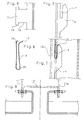
- Fig. 1 ein Ausführungsbeispiel für ein Wandverkleidungselement einer erfindungsgemäßen Fassadenverkleidung, das in Tragschienen mit Klinkkonsolen eingehängt sind, in einer Vorderansicht,
- Fig. 2 das erfindungsgemäße Verkleidungselement und die Tragschienen gemäß der Fig. 1 in einer Vertikalschnitt,
- Fig. 3 das Verkleidungselement und die Tragschienen in Aufsicht, teilweise geschnitten,
- Fig. 4 einen Klinksteg eines Verkleidungselementes,
- Fig. 5 eine auf einem Tragschienenprofil ausgebildete Klinkkonsole zum Einhängen eines Klinksteges,
- Fig. 6 Einen Federclip zum Aufschieben auf einen Klinksteg,
- Fig. 7 den Federclip nach Fig. 6, der auf einen in eine Einschlitzung in einer Klinkkonsole eingreifenden Klinksteg aufgeschoben ist, und
- Fig. 8 ein weiteres Ausführungsbeispiel für ein Verkleidungselement einer erfindungsgemäßen Fassadenverkleidung, teilweise horizontal geschnitten.
- 1 shows an embodiment of a wall cladding element of a facade cladding according to the invention, which are suspended in mounting rails with latch brackets, in a front view,
- 2 the cladding element according to the invention and the mounting rails according to FIG. 1 in a vertical section,
- 3 the cladding element and the mounting rails in supervision, partially cut,
- 4 a latch web of a cladding element,
- 5 a latching bracket formed on a mounting rail profile for hanging a latching web,
- Fig. 6 A spring clip for sliding onto one Klinksteg,
- FIG. 7 shows the spring clip according to FIG. 6, which is pushed onto a latching web engaging in a slot in a latching console, and
- Fig. 8 shows another embodiment of a cladding element of a facade cladding according to the invention, partially cut horizontally.
In den Fig. 2 bis 3 ist mit Bezugszeichen 1 ein kassettenförmiges Verkleidungselement bezeichnet, das einen Kassettenboden 2 und an einander gegenüberliegenden, vertikal verlaufend vorgesehenen Rändern eine Abkantung 3 bzw. 3a aufweist. Die Abkantungen 3 und 3a umfassen eine erste, zu dem Kassettenboden 2 senkrechte Abkantung 8 bzw. 8a und eine von der senkrechten Abkantung 8 bzw. 8a in Bezug auf die Fläche des Kassettenbodens nach innen abgewinkelte und parallel zu der Fläche des Kassettenbodens 2 verlaufende zweite Abkantung 9 bzw. 9a. Von den Abkantungen 9 und 9a stehen als Klinklaschen 5 bzw. 5a ausgebildete Klinkstege 5 bzw. 5a vor. Das Verkleidungselement 1 umfasst ferner an seinem oberen Rand eine Abkantung 4, die eine erste, zum Kassettenboden 2 senkrechte Abkantung 11 und eine zweite, von der Abkantung 11 nach oben abgewinkelte Abkantung 10 umfaßt. Wie insbesondere der Fig. 3 zu entnehmen ist, weist die Abkantung 11 eine größere Länge als die Abkantung 12 auf. In dem vorliegenden Ausführungsbeispiel beträgt der Abstand der Klinklaschen 5 und 5a vom Kassettenboden ca. 50 mm.2 to 3,
Mit 13 und 13a sind in den Fig. 1 bis 3 die Ausläufer der Tragschienenprofile bezeichnet. Diese als Unterkonstruktion dienenden Tragschienenprofile sind über einen Schenkel 17 bzw. 17a mit der zu verkleidenden Wand verbunden, während ein bis zu dem Schenkel 17 bzw. 17a senkrechter Schenkel in einem bestimmten Rasterabstand, im vorliegenden Beispiel im Abstand von 10 cm, Klinkkonsolen 6 aufweist, die einstückig mit diesem Schenkel ausgebildet sind.With 13 and 13a in FIGS. 1 to 3, the foothills of the mounting rail profiles are designated. These support rail profiles, which serve as a substructure, are connected to the wall to be clad via a
In Fig. 4, in der eine Klinklasche 5 gesondert dargestellt ist, ist mit 14 eine durch eine Nase 15 begrenzte Ausnehmung bezeichnet, die einen Sitz für den Federclip 16 bildet, der in der Fig. 6 gesondert dargestellt ist und der eine dieser Ausnehmung entsprechende Breite, und wie der Fig. 6 zu entnehmen ist, an seinem oberen Ende Abkrümmungen 18 und 19 aufweist.In Fig. 4, in which a
In der Fig. 5, die gesondert eine Klinkkonsole 6 zeigt, ist mit 7 eine Einschlitzung für den Eingriff einer Klinklasche 5 bezeichnet.In FIG. 5, which separately shows a
Zur Montage der Fassadenverkleidung werden die Verkleidungselemente 1 mit den Klinklaschen 5 in die Einschlitzungen 7 der Klinkkonsolen 6 eingehängt, wobei in vorliegendem Ausführungsbeispiel jede Klinkkonsole des Tragschienenprofils 13 bzw. 13a genutzt wird. Im vorliegenden Ausführungsbeispiel beträgt die Rasterweite der Klinklaschen 10 cm. Wie in der Fig. 2 erkennbar ist, überlappen sich vertikal übereinander angeordnete Verkleidungselemente, indem das jeweils obere Verkleidungselement 1a über die Abkantung 10 der oberen Abkantung 4 des jeweils unteren Verkleidungselements 1 übersteht. Indem die untere Abkantung 12a des oberen Verkleidungselements 1a kürzer ist als die erste Abkantung 11 der Abkantung 4 des jeweils unteren Verkleidungselements ist, kann die Abkantung 10 am oberen Ende eines Verkleidungselements jeweils bis unter das darüber liegende Verkleidungselement vorstehen. Dadurch ist gesichert daß die Verkleidungselemente sich in senkrechter Richtung überlappen und die Kassettenböden praktisch bündig aneinander anschließen. Der Einhängeweg in Richtung zur Wand beträgt im vorliegenden Ausführungsbeispiel 15 mm. Bei einer Konstruktionstiefe von 60 mm kann bereits auf eine Klinkung der Unterkonstruktion für die horizontalen Fassadenfugen verzichtet werden.To assemble the facade cladding, the
In der Fig. 8 in der ein Ausführungsbeispiel für einen Stoß zwischen zwei horizontal aneinandergrenzenden Verkleidungselementen gezeigt ist, ist mit 13′ eine zweckmäßig als H-Profil ausgebildete Tragschiene bezeichnet, deren seitliche Schenkel 17 und 17a mit Klinkkonsolen gemäß der Fig. 5 versehen sind. Durch diese vorteilhafte Ausbildung des Tragschienenprofils als H-Profil ist zur horizontalen Verbindung jeweils zweier horizontal aneinandergrenzender Platten nur eine Tragschiene erforderlich.In Fig. 8 in which an embodiment of a joint between two horizontally adjacent cladding elements is shown, 13 'is an expediently designed as an H-profile support rail, whose
Durch die Verwendung der Federclips 16 erfolgt eine Ruhigstellung der Klinklaschen 5 in den Einschlitzungen 7 der Klinkkonsole 6, so daß, z. B. durch Windeinwirkungen ausgelöste Klappergeräusche vermieden werden. Aus der Figur 7 ist ersichtlich, wie durch den Federclip 16 eine Einklemmung der Lasche 5 in der Einschlitzung 7 erfolgt. Vor allem indem der Clip nahe dem unteren Ende zusammengedrückt wird, kann über den Clip eine kraftschlüssige Verbindung zwischen der Klinklasche und der Klinkkonsole hergestellt werden. Da der Federclip in der Breite der Ausnehmung 14 in der Klinklasche 5 entspricht, ist durch die Ausnehmung 14 ein Sitz für die Klinklasche gebildet, so daß der Federclip, der länger als die Klinklasche ist, nachdem er auf die Klinklasche geschoben worden ist, weder in vertikaler noch in horizontaler Richtung ohne Krafteinwirkung von der Klinklasche abgestreift werden kann, indem die Abkrümmung 18 und die Nase 15 jeweils einen vertikalen bzw. horizontalen Anschlag bilden. Indem für den Federclip bzw. die Klinklasche eine verhältnismäßig große Breite, im vorliegenden Beispiel 15 mm bzw. 20 mm vorgesehen wird, ist ein großer Bewegungsspielraum für Einbautoleranzen und Währmeausdehnungen gewährleistet. Die Nase 15 verhindert, daß die mit dem Federclip versehene Klinklasche aus der Einschlitzung der Klinkkonsole bei seitlicher Verschiebung herausrutscht. Indem der Federclip aus Metall besteht, ist eine elektrische Verbindung von den Verkleidungselementen zur Unterkonstruktion hergestellt, so daß vorteilhaft für die ganze Wandverkleidung nur eine einzige Erdungsleitung erforderlich wird.By using the spring clips 16, the
Die enge Rasterung der Aufhängepunkte trägt dazu bei, daß das Aussehen der Fassadenverkleidung beeinträchtigende Deformationen der Verkleidungselemente vermieden werden. Indem der Rand der Kassettenböden an den vertikalen Seiten jeweils C-förmig umgefalzt ist, ergibt sich eine hohe Verwindungssteifigkeit der kassettenartigen Verkleidungselemente, so daß auch Deformationen dieser beim Transport weitgehend vermieden werden können. Die enge Rasterung der Klinklaschen bzw. der Klinkkonsolen macht ein projektbezogenes Berechnen der Aufhängepunkte der Verkleidungselemente überflüssig. Aufwendige Arbeiten zur projektbezogenen Vorfertigung der Verkleidungselemente und Tragschienen entfallen. Bei Längenangaben die dem Montagepersonal für die Arbeit vor Ort mitgeteilt werden müssen, kann man sich weitgehend auf die Rastermaße stützen. Die Tragschienen können vorteilhaft in Standardlängen hergestellt werden. Ein sortieren projektbezogen hergestellter Tragschienen vor Ort entfällt. Die in Standardlängen hergestellten Tragschienen weisen auch Vorteile in Bezug auf die Vorbehandlung, z.B. das Aufbringen einer Beschichtung auf, indem die Teile gleicher Länge in einer dafür zugeschnittenen Behandlungseinrichtung vorbearbeitet werden können. Da die Tragschienen in einer Standardlänge zur Baustelle angeliefert werden können, ergeben sich auch Vorteile im Bezug auf die Lagerhaltung. Restschienen können gegebenenfalls nur nach einer Umlackierung, auf jeder anderen Baustelle weiterverwendet werden. An den Elementen brauchen weder vor noch nach der Beschichtung Befestigungselemente angebracht werden. Damit entfällt die Gefahr der Spaltkorrosion durch Chromtierungsrückstände bzw. es müssen nachträglich keine Beschichtungen von Befestigungsmittel vorgenommen werden.The narrow grid of the suspension points helps to prevent deformation of the cladding elements that impair the appearance of the facade cladding. The fact that the edge of the cassette bottoms is folded in a C-shape on the vertical sides results in a high torsional rigidity of the cassette-like cladding elements, so that deformations of these during transport can be largely avoided. The tight grid of the latches or the latch brackets makes a project-related calculation of the suspension points of the cladding elements unnecessary. Time-consuming work for the project-related prefabrication of the cladding elements and mounting rails is eliminated. For length information that must be communicated to the assembly staff for the work on site, you can largely rely on the grid dimensions. The mounting rails can advantageously be manufactured in standard lengths. There is no need to sort on-site manufactured mounting rails on site. The support rails manufactured in standard lengths also have advantages in terms of pretreatment, e.g. the application of a coating in that the parts of the same length can be pre-processed in a treatment device tailored for this purpose. Since the mounting rails can be delivered to the construction site in a standard length, there are also advantages in terms of warehousing. Residual rails may only be reused on any other construction site after repainting. Fastening elements need not be attached to the elements either before or after the coating. This eliminates the risk of crevice corrosion due to chrome plating residues and there is no need to subsequently coat fasteners.
Claims (7)
- Façade facing with cassette-type facing elements (1) which comprise a cassette bottom (2) and, at least on mutually opposite, vertically extending edges, edge bends (3, 3a; 4, 4a) bent away from the cassette bottom (2) in the direction of a substructure, there being provided in the vertically extending, lateral edge regions of the facing elements catch facilities arranged laterally at a distance from one another for suspending the facing elements (1) in corresponding holding facilities provided on the substructure, the catch facilities being formed by catch webs (5) which are provided on the edge bends, extend at a distance from the cassette bottom (2) and essentially parallel thereto, and project from the edge bend, and the holding facilities being formed by catch brackets (6), provided on essentially vertically extending support rails, with slits (7) for the engagement of the catch webs (5), characterised in that each vertical edge bend (3, 3a) comprises a first bend (8, 8a) bent away from the cassette bottom and a second bend (9, 9a) bent away from the first bend, that the catch webs (5) project from the second bend (9, 9a) of the edge bend (3, 3a), that the catch webs (5) are held resiliently in the slits (7) of the catch brackets (6) by a clamping facility formed by an essentially U-shaped spring clip (16) which can be pushed onto the catch webs, and that the catch brackets are arranged at the same height on the façade at a modular distance.
- Façade facing according to Claim 1, characterised in that the modular distance is approximately 0.1 m.
- Façade facing according to one of Claims 1 and 2, characterised in that the catch webs (5) are arranged at the same height in each case opposite one another on the mutually opposite, vertically extending edges of the facing elements (1).
- Façade facing according to one of Claims 1 to 3, characterised in that the support rails with the catch brackets (6) are designed essentially in the form of U-shaped or H-shaped profiles.
- Façade Facing according to one of Claims 1 to 4, characterised in that the catch webs (5) have in their lower edge a recess (14) forming a seat for the closed end of the U-shaped spring clip (16).
- Façade facing according to one of Claims 1 to 5, characterised in that the catch webs have on their lower edge a stop nose (15) for contact against the catch bracket (6).
- Façade facing according to one of Claims 1 to 6, characterised in that the catch webs (5) are arranged along the bend at a modular distance which is equal to or a multiple of the modular distance of the catch brackets (6).
Priority Applications (1)
| Application Number | Priority Date | Filing Date | Title |
|---|---|---|---|
| AT91102069T ATE81700T1 (en) | 1990-02-21 | 1991-02-14 | FAÇADE CLADDING. |
Applications Claiming Priority (2)
| Application Number | Priority Date | Filing Date | Title |
|---|---|---|---|
| DE4005508A DE4005508C2 (en) | 1990-02-21 | 1990-02-21 | Facade cladding |
| DE4005508 | 1990-02-21 |
Publications (2)
| Publication Number | Publication Date |
|---|---|
| EP0443433A1 EP0443433A1 (en) | 1991-08-28 |
| EP0443433B1 true EP0443433B1 (en) | 1992-10-21 |
Family
ID=6400683
Family Applications (1)
| Application Number | Title | Priority Date | Filing Date |
|---|---|---|---|
| EP91102069A Expired - Lifetime EP0443433B1 (en) | 1990-02-21 | 1991-02-14 | Façade covering |
Country Status (3)
| Country | Link |
|---|---|
| EP (1) | EP0443433B1 (en) |
| AT (1) | ATE81700T1 (en) |
| DE (1) | DE4005508C2 (en) |
Families Citing this family (3)
| Publication number | Priority date | Publication date | Assignee | Title |
|---|---|---|---|---|
| FR2697298B1 (en) * | 1992-10-28 | 1995-01-13 | Profilor Sa | Connection and assembly structure of covering parts constituting an external covering with respect to a given support. |
| DE4421614C2 (en) * | 1994-06-21 | 2000-01-05 | Sommer Metallbau Stahlbau Gmbh | Facade cladding |
| US5575124A (en) * | 1995-03-29 | 1996-11-19 | Novello, Jr.; Eligio | Construction with modular walls |
Family Cites Families (5)
| Publication number | Priority date | Publication date | Assignee | Title |
|---|---|---|---|---|
| DE3517443A1 (en) * | 1985-05-14 | 1986-11-20 | Straub GmbH & Co Metallbau, 8857 Wertingen | HOLDING CONSTRUCTION FOR VENTILATED FACADES FROM SHELL-SHAPED FACADE ELEMENTS |
| GB2188075B (en) * | 1986-03-12 | 1989-12-06 | Crittall Windows Ltd | Building cladding |
| AT385305B (en) * | 1986-06-02 | 1988-03-25 | Bug Alutechnik | Profile bar for fastening facade elements |
| DE8621152U1 (en) * | 1986-08-07 | 1987-12-03 | Christian Pohl GmbH, 5000 Köln | Kit consisting of individual construction elements for wall or ceiling cladding on buildings |
| DE3733359A1 (en) * | 1987-10-02 | 1989-04-13 | Hupfeld & Schloeffel Metallbau | Facade which can be fitted on a building wall |
-
1990
- 1990-02-21 DE DE4005508A patent/DE4005508C2/en not_active Expired - Fee Related
-
1991
- 1991-02-14 EP EP91102069A patent/EP0443433B1/en not_active Expired - Lifetime
- 1991-02-14 AT AT91102069T patent/ATE81700T1/en not_active IP Right Cessation
Also Published As
| Publication number | Publication date |
|---|---|
| DE4005508A1 (en) | 1991-08-22 |
| EP0443433A1 (en) | 1991-08-28 |
| ATE81700T1 (en) | 1992-11-15 |
| DE4005508C2 (en) | 2001-08-16 |
Similar Documents
| Publication | Publication Date | Title |
|---|---|---|
| DE60216008T2 (en) | Rail device for supporting wall posts, method and wall frame arrangement | |
| DE2945148C2 (en) | Device for attaching thermal insulation panels to the frame of a window | |
| DE3139829A1 (en) | POSTS FOR A REMOVABLE PARTITION | |
| EP0180837B2 (en) | Locating device kit for curtain walls | |
| DE3726255A1 (en) | Partition wall | |
| EP3548412A2 (en) | Connecting device and method for connecting a wall element in an elevator car | |
| DE2610998C3 (en) | Bracket for fastening cladding panels in front of a building wall | |
| EP3222794B1 (en) | Holding device for applying plate-shaped wall or ceilings cladding elements to a substructure at a construction site and method for producing said holding device | |
| EP0443433B1 (en) | Façade covering | |
| DE102017101509A1 (en) | Console for fixing facade elements | |
| DE2927164A1 (en) | Modular panel facade cladding mounting - involves opposite sloped flanges screwed to vertical bars and locking behind tongues | |
| DE20214938U1 (en) | Facade system made of ceramic facade panels for use as a rear-ventilated facade on a load-bearing building wall | |
| EP0010694B1 (en) | Lining for walls or ceilings | |
| DE20200530U1 (en) | Substructure for wall cladding of buildings with wall cladding panels made of a solid material | |
| AT1026U1 (en) | PROFILE RAIL | |
| DE3245851A1 (en) | RAILING | |
| DE2606726C2 (en) | Non-load-bearing wall construction | |
| DE8417333U1 (en) | SUSPENSION DEVICE FOR C-SHAPED RAILS FROM BLANKET OD. DGL. | |
| EP0639680B1 (en) | Hanger for suspended ceilings | |
| DE20114555U1 (en) | Anchor angle | |
| DE9102531U1 (en) | Ceiling paneling | |
| DE19932528C1 (en) | Coupling clip for support or trim profiles for wall cladding material has central section bridging gap between profile ends and 2 opposing end tongues spaced apart by less than width of central section | |
| DE2103993A1 (en) | Cladding for air conditioning induction devices and directors | |
| DE19625315A1 (en) | Wall cladding system for bathrooms and kitchens - involves angled profiles and spacer bent in-situ to suit wall interval in sequence of installation stages | |
| DE20105400U1 (en) | Assembly aid for fastening a substructure to accommodate wall or ceiling cladding |
Legal Events
| Date | Code | Title | Description |
|---|---|---|---|
| PUAI | Public reference made under article 153(3) epc to a published international application that has entered the european phase |
Free format text: ORIGINAL CODE: 0009012 |
|
| 17P | Request for examination filed |
Effective date: 19910214 |
|
| AK | Designated contracting states |
Kind code of ref document: A1 Designated state(s): AT CH FR GB LI |
|
| 17Q | First examination report despatched |
Effective date: 19911029 |
|
| GRAA | (expected) grant |
Free format text: ORIGINAL CODE: 0009210 |
|
| AK | Designated contracting states |
Kind code of ref document: B1 Designated state(s): AT CH FR GB LI |
|
| REF | Corresponds to: |
Ref document number: 81700 Country of ref document: AT Date of ref document: 19921115 Kind code of ref document: T |
|
| ET | Fr: translation filed | ||
| GBT | Gb: translation of ep patent filed (gb section 77(6)(a)/1977) |
Effective date: 19930127 |
|
| PLBE | No opposition filed within time limit |
Free format text: ORIGINAL CODE: 0009261 |
|
| STAA | Information on the status of an ep patent application or granted ep patent |
Free format text: STATUS: NO OPPOSITION FILED WITHIN TIME LIMIT |
|
| 26N | No opposition filed | ||
| PGFP | Annual fee paid to national office [announced via postgrant information from national office to epo] |
Ref country code: CH Payment date: 19940118 Year of fee payment: 4 |
|
| PGFP | Annual fee paid to national office [announced via postgrant information from national office to epo] |
Ref country code: FR Payment date: 19940121 Year of fee payment: 4 |
|
| PGFP | Annual fee paid to national office [announced via postgrant information from national office to epo] |
Ref country code: AT Payment date: 19940214 Year of fee payment: 4 |
|
| PG25 | Lapsed in a contracting state [announced via postgrant information from national office to epo] |
Ref country code: GB Effective date: 19950214 Ref country code: AT Effective date: 19950214 |
|
| PG25 | Lapsed in a contracting state [announced via postgrant information from national office to epo] |
Ref country code: LI Effective date: 19950228 Ref country code: CH Effective date: 19950228 |
|
| GBPC | Gb: european patent ceased through non-payment of renewal fee |
Effective date: 19950214 |
|
| PG25 | Lapsed in a contracting state [announced via postgrant information from national office to epo] |
Ref country code: FR Effective date: 19951031 |
|
| REG | Reference to a national code |
Ref country code: FR Ref legal event code: ST |