EP0442338B1 - Optische Ueberwachungseinrichtung - Google Patents
Optische Ueberwachungseinrichtung Download PDFInfo
- Publication number
- EP0442338B1 EP0442338B1 EP91101423A EP91101423A EP0442338B1 EP 0442338 B1 EP0442338 B1 EP 0442338B1 EP 91101423 A EP91101423 A EP 91101423A EP 91101423 A EP91101423 A EP 91101423A EP 0442338 B1 EP0442338 B1 EP 0442338B1
- Authority
- EP
- European Patent Office
- Prior art keywords
- surveillance
- housing
- objective
- monitoring
- units
- Prior art date
- Legal status (The legal status is an assumption and is not a legal conclusion. Google has not performed a legal analysis and makes no representation as to the accuracy of the status listed.)
- Expired - Lifetime
Links
- 230000003287 optical effect Effects 0.000 title claims description 13
- 238000012806 monitoring device Methods 0.000 title description 9
- 239000000725 suspension Substances 0.000 claims description 17
- 230000008878 coupling Effects 0.000 claims description 14
- 238000010168 coupling process Methods 0.000 claims description 14
- 238000005859 coupling reaction Methods 0.000 claims description 14
- 230000015654 memory Effects 0.000 claims description 4
- 230000006870 function Effects 0.000 claims description 3
- 230000004888 barrier function Effects 0.000 claims description 2
- 238000012544 monitoring process Methods 0.000 abstract description 50
- 230000000694 effects Effects 0.000 abstract description 4
- 238000009434 installation Methods 0.000 abstract description 3
- 230000001960 triggered effect Effects 0.000 description 4
- 238000000034 method Methods 0.000 description 2
- 230000008569 process Effects 0.000 description 2
- 230000008859 change Effects 0.000 description 1
- 238000010276 construction Methods 0.000 description 1
- 238000010586 diagram Methods 0.000 description 1
- 238000005516 engineering process Methods 0.000 description 1
- 125000006850 spacer group Chemical group 0.000 description 1
Images


Classifications
-
- G—PHYSICS
- G08—SIGNALLING
- G08B—SIGNALLING OR CALLING SYSTEMS; ORDER TELEGRAPHS; ALARM SYSTEMS
- G08B13/00—Burglar, theft or intruder alarms
- G08B13/18—Actuation by interference with heat, light, or radiation of shorter wavelength; Actuation by intruding sources of heat, light, or radiation of shorter wavelength
- G08B13/189—Actuation by interference with heat, light, or radiation of shorter wavelength; Actuation by intruding sources of heat, light, or radiation of shorter wavelength using passive radiation detection systems
- G08B13/194—Actuation by interference with heat, light, or radiation of shorter wavelength; Actuation by intruding sources of heat, light, or radiation of shorter wavelength using passive radiation detection systems using image scanning and comparing systems
- G08B13/196—Actuation by interference with heat, light, or radiation of shorter wavelength; Actuation by intruding sources of heat, light, or radiation of shorter wavelength using passive radiation detection systems using image scanning and comparing systems using television cameras
- G08B13/19617—Surveillance camera constructional details
- G08B13/19632—Camera support structures, e.g. attachment means, poles
-
- G—PHYSICS
- G08—SIGNALLING
- G08B—SIGNALLING OR CALLING SYSTEMS; ORDER TELEGRAPHS; ALARM SYSTEMS
- G08B13/00—Burglar, theft or intruder alarms
- G08B13/18—Actuation by interference with heat, light, or radiation of shorter wavelength; Actuation by intruding sources of heat, light, or radiation of shorter wavelength
- G08B13/189—Actuation by interference with heat, light, or radiation of shorter wavelength; Actuation by intruding sources of heat, light, or radiation of shorter wavelength using passive radiation detection systems
- G08B13/194—Actuation by interference with heat, light, or radiation of shorter wavelength; Actuation by intruding sources of heat, light, or radiation of shorter wavelength using passive radiation detection systems using image scanning and comparing systems
- G08B13/196—Actuation by interference with heat, light, or radiation of shorter wavelength; Actuation by intruding sources of heat, light, or radiation of shorter wavelength using passive radiation detection systems using image scanning and comparing systems using television cameras
- G08B13/19617—Surveillance camera constructional details
- G08B13/19619—Details of casing
-
- G—PHYSICS
- G08—SIGNALLING
- G08B—SIGNALLING OR CALLING SYSTEMS; ORDER TELEGRAPHS; ALARM SYSTEMS
- G08B13/00—Burglar, theft or intruder alarms
- G08B13/18—Actuation by interference with heat, light, or radiation of shorter wavelength; Actuation by intruding sources of heat, light, or radiation of shorter wavelength
- G08B13/189—Actuation by interference with heat, light, or radiation of shorter wavelength; Actuation by intruding sources of heat, light, or radiation of shorter wavelength using passive radiation detection systems
- G08B13/194—Actuation by interference with heat, light, or radiation of shorter wavelength; Actuation by intruding sources of heat, light, or radiation of shorter wavelength using passive radiation detection systems using image scanning and comparing systems
- G08B13/196—Actuation by interference with heat, light, or radiation of shorter wavelength; Actuation by intruding sources of heat, light, or radiation of shorter wavelength using passive radiation detection systems using image scanning and comparing systems using television cameras
- G08B13/19617—Surveillance camera constructional details
- G08B13/1963—Arrangements allowing camera rotation to change view, e.g. pivoting camera, pan-tilt and zoom [PTZ]
Definitions
- the invention relates to an optical monitoring device with a plurality of monitoring units which can be rotated about a suspension, each monitoring unit having a housing for pivotably accommodating at least one camera, from which only the lens is perceptible to the outside, and furthermore, dummy lenses are pivotably arranged on each housing, and with a device common to the monitoring units for controlling camera and movement functions.
- monitoring devices are e.g. known from DE-A-2 850 419 or from US-A-3 535 442.
- Such devices are used to monitor publicly accessible locations, such as Shops, used.
- the individual surveillance units are traditionally supposed to essentially perform two functions, namely, on the one hand, to enable video surveillance of the premises to be as targeted as possible and, on the other hand, to deter potential thieves from the outset. For cost reasons, it is also sought that, with the optimal deterrent effect, as few video cameras as possible have to be used without the potential thief noticing this.
- the aim is to design the monitoring device in such a way that it can also be used as a "management control" and information system which enables the store manager to gain an overview of the processes in the shop and to intervene accordingly.
- All of the monitoring units in a local can be equipped with a camera or only a part thereof, with in extreme cases only one monitoring unit having a camera.
- the monitoring units can now be replaced by the personnel themselves in such a way that new monitoring focal points can be formed at any time by exchanging equipped units for others and vice versa.
- Corresponding programs for the operation of the facility are stored and can be exchanged accordingly.
- the arrangement of loudspeakers in each case parallel to the lenses or dummy objects allows on the one hand to make announcements to the shop users, which means that the installation of a separate loudspeaker system can be saved.
- the swiveling loudspeakers have a pronounced deterrent effect on a potential thief, since he recognizes this as a means of alerting staff and customers.
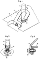
- a single monitoring unit 1 is initially shown in its outer shape. Their design is important insofar as it is intended to have the greatest possible deterrent effect on potential thieves.
- the monitoring unit has a housing 10 in which the entire mechanics and electronics are accommodated as a self-supporting functional unit 11 (cf. FIG. 3).
- the functional unit 11 is connected via an electro-mechanical quick coupling 20 (FIG. 5) to be described, to a suspension 12 which is fixedly arranged on the ceiling of a restaurant.
- the housing 10 has two parallel, adjacent slot openings 14 which extend over an underlying circular sector of approximately 180 °. Through these slit openings 14 two blinds 15 can be seen from the outside, in each of which a camera lens 16 or a dummy and a loudspeaker 17 or a dummy are arranged on each side. Camera lenses 16 and loudspeakers 17, together with the blinds 15, can be pivoted along the slots, namely between an almost horizontal and a steeply downward position (cf. FIG. 3).
- the arrangement is such that a thief must assume that each camera lens 16 (or dummy) can be swiveled through the entire slit opening, ie the full sector, by 180 ° by not being able to recognize the lower position limit.
- the loudspeaker 17 is pivoted parallel to each camera lens 16. The moveable speaker acts as a deterrent to the thief because he has to assume that a targeted alarm will be triggered after being caught.
- the entire arrangement is rotatable about the suspension 12. As can be seen from FIG. 1, the lateral areas appear to be out of observation at a certain rotational position. For this reason, camera-like protrusions 18 with a dark window 13 below are arranged on the side of the two slot openings 14 on the housing 10. A light-emitting diode or the like can be arranged behind the window 13, which gives the impression of active observation.
- a quick coupling 20 is provided between the monitoring units 1 and the suspensions 12 permanently mounted in the locality, by means of which the mechanical as well as the electrical connection can be established at the same time.
- a union nut 21 is provided at the bottom of each suspension 12 and can be fastened to the monitoring unit via a coupling part 22.
- the coupling part 22 remains stationary, while the functional unit 11 is mounted inside the housing on the plug part 22 and can be rotated relative to the latter by means of a first motor M1.
- a safety bracket 23 is fastened to the housing 10, which tightly encompasses the suspension 12. If the coupling 20 is released, the safety bracket 23 remains on the union nut 21 hang.
- the arrangement is such that the clutch 20 can only be closed when the bracket 23 has already been inserted into the suspension 12, so that the securing is ensured even during the assembly process. Since the safety bracket lies closely against the suspension 12 and rotates relative to it together with the monitoring unit 1, it must be avoided that the bracket presses against the suspension and thus causes a large amount of friction or squeaking noises. For this reason, the safety bracket 23, as can be seen in FIG. 6, is fastened to the housing 10 in an easily movable manner. For this purpose, a spacer sleeve 24 is provided, which is slightly thicker than the bracket wall, with which the bracket is forcibly attached to the housing 10 loosely.
- each monitoring unit 1 there is a functional unit 11 which is rotatably suspended on the coupling part 22.
- the functional unit 11 has a support part 30 with two outer holding plates 31 and two central struts 32.
- a rocker 33 is arranged on each side between the struts 32 and the holding plates 31.
- Fig. 3 only one of the two rockers 33 can be seen.
- the rockers are mounted on a pivot axis 34 in the support part 30.
- a swivel motor M2 (not shown in FIG. 3) is also arranged in the support part, by means of which the rockers 33 can be swiveled.
- the circularly curved cover plates 15 with camera lenses 16 and loudspeakers 17 are arranged on the rockers.
- the video camera 19 can also be attached to one of the rockers.
- Stepper motors which are controlled incrementally are preferably used as motors.
- the speed of rotary motor M1 as well as swivel motor M2 can thus be infinitely and optionally adjusted by computer control.
- an adjustment between 99 preprogrammed positions that can be changed at any time is possible both vertically and horizontally.
- the camera 19 is therefore preferably equipped with an adjustable zoom lens for variable focal lengths and image sections, the zoom position also being preprogrammable for each programmed position.
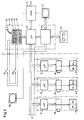
- each monitoring unit 1 is connected via the suspension 12 to a central control device 40 which is arranged in a monitoring room (cf. FIG. 2).
- the arrangement is such that all monitoring units are connected to two lines 41 drawn in parallel, which allows a much simpler installation than previous star-shaped connections.
- the central control device 40 has a computer 42 with an input / output unit 43.
- a videoswitch 44 with two independent programmable program units is used to switch and interconnect a video device 45, the cameras 19 and the monitors 46, 47, one of which is in the monitoring room and one or several are set up in the monitored premises themselves.
- the monitoring program which can be displayed on the monitor 46 can thus be programmed independently of the program which is visible on the public monitor 47.
- the monitor 47 in the surveillance room transmits the images of the camera 19 that is in operation, for example according to a certain sequence
- the video switch and the video device 45 on the monitor 46 can be used to mix surveillance scenes stored in the monitored location from the different locations of the cameras that are not currently active can be imported with real-time images. Realtime images of the currently active camera and previously recorded, stored images from the perspectives of the non-active monitoring units thus alternately appear on the monitor 46.
- the potential thief thus has the impression that all monitoring units are active, so that inactive units cannot be recognized.
- the corresponding control programs can be created by means of the input / output unit 43 and stored in a plug-in RAM memory 51 of e.g. 32 K-bytes of storage capacity can be saved.
- a plug-in RAM memory 51 of e.g. 32 K-bytes of storage capacity can be saved.
- several different monitoring programs can easily be exchanged and e.g. can be adapted to a change in the active monitoring unit 1.
- a program with up to 99 different positions of the monitoring units can be stored in each memory 51. Since the memories 51 can be exchanged, the number of positions of the monitoring units that can be achieved is fundamentally unlimited.
- the input and output unit 43 has an input keyboard 48 and an alphanumeric display 49 on which the respectively active monitoring unit 1 is labeled in words to facilitate operation.
- the central control unit 40 also has, in a conventional manner, means for manual control. Furthermore, the control of the monitoring units 1 can also be triggered externally. For this purpose, switches S 1, S 2 .. can be connected to the control unit 40, which are anodized in the monitored premises in the form of light barriers, proximity switches, and alarm cargo or other goods security systems. If such a switch (eg S1) is triggered, one or more of the monitoring units 1 swings according to the program to the corresponding point. With the video device then also activated In this case an image of the thief can be taken.
- switches S 1, S 2 .. can be connected to the control unit 40, which are anodized in the monitored premises in the form of light barriers, proximity switches, and alarm cargo or other goods security systems. If such a switch (eg S1) is triggered, one or more of the monitoring units 1 swings according to the program to the corresponding point. With the video device then also activated In this case an image of the thief can be taken.
- the same device can also be used as customer information means, e.g. upon external triggering of a switch S 1, S 2, etc., customer information relating to the respective products is transmitted via the loudspeakers 17 of the corresponding monitoring unit 1. If a monitor 46 is provided in this area, an information film can also be played on this monitor instead of the surveillance images. Such an information film can e.g. be triggered by the customer himself by actuating a corresponding switch S 1.
- a microphone 50 is provided on the input and output unit 43, via which the control person can use the loudspeaker 17 of the corresponding monitoring unit to address a customer individually.
- the image of the speaking person preferably appears on the corresponding monitor 46, for which purpose a video camera (not shown) can also be provided in the monitoring room.
- a (directional) microphone is arranged on the monitoring unit, via which the customer can communicate with the operator.
- a processor 42 with the described input / output and storage options is provided in the central control device, which cooperates as master in master-slave operation with local processors 9 in the monitoring units 1. He sends them their respective individual operating programs, after which they control the individual components individually.
- the monitoring device described allows a versatile use, which optimal deterrence with very good monitoring options connect. It can also be used as information and / or alarm means.
Landscapes
- Physics & Mathematics (AREA)
- General Physics & Mathematics (AREA)
- Closed-Circuit Television Systems (AREA)
- Geophysics And Detection Of Objects (AREA)
- Burglar Alarm Systems (AREA)
- Studio Devices (AREA)
- Alarm Systems (AREA)
Applications Claiming Priority (2)
| Application Number | Priority Date | Filing Date | Title |
|---|---|---|---|
| CH450/90 | 1990-02-13 | ||
| CH450/90A CH679813A5 (enExample) | 1990-02-13 | 1990-02-13 |
Publications (2)
| Publication Number | Publication Date |
|---|---|
| EP0442338A1 EP0442338A1 (de) | 1991-08-21 |
| EP0442338B1 true EP0442338B1 (de) | 1995-10-11 |
Family
ID=4187311
Family Applications (1)
| Application Number | Title | Priority Date | Filing Date |
|---|---|---|---|
| EP91101423A Expired - Lifetime EP0442338B1 (de) | 1990-02-13 | 1991-02-04 | Optische Ueberwachungseinrichtung |
Country Status (6)
| Country | Link |
|---|---|
| US (1) | US5204742A (enExample) |
| EP (1) | EP0442338B1 (enExample) |
| AT (1) | ATE129086T1 (enExample) |
| CH (1) | CH679813A5 (enExample) |
| DE (1) | DE59106638D1 (enExample) |
| DK (1) | DK0442338T3 (enExample) |
Families Citing this family (6)
| Publication number | Priority date | Publication date | Assignee | Title |
|---|---|---|---|---|
| US5319394A (en) | 1991-02-11 | 1994-06-07 | Dukek Randy R | System for recording and modifying behavior of passenger in passenger vehicles |
| US5282182A (en) | 1991-11-12 | 1994-01-25 | Kreuzer Monroe E | Video monitor and housing assembly |
| DE19758371A1 (de) * | 1997-12-29 | 1999-07-08 | Francois Sanvi D Dipl In Sodji | Vorrichtung zur Überwachung eines Gebäudes und/oder Raumes |
| EP1209516B1 (en) * | 2000-11-14 | 2004-10-20 | Bridisco Limited | A camera |
| USD520548S1 (en) * | 2004-10-26 | 2006-05-09 | Inventec Multimedia & Telecom Corporation | Image recorder |
| DE102019122373B3 (de) * | 2019-08-20 | 2020-12-10 | Dallmeier Electronic Gmbh & Co. Kg | Halteanordnung und Verfahren zur hängenden Montage eines Objekts, insbesondere einer Überwachungskamera |
Family Cites Families (12)
| Publication number | Priority date | Publication date | Assignee | Title |
|---|---|---|---|---|
| US3535442A (en) * | 1967-10-19 | 1970-10-20 | John E Jennings | Anti-shoplifting and surveillance system |
| DE1805170C3 (de) * | 1968-10-25 | 1974-11-21 | Hibbard, Ronald C., Los Angeles, Calif. (V.St.A.) | Überwachungsvorrichtung für Räume mit einem Behälter zur Aufnahme einer Kamera |
| US3638502A (en) * | 1969-12-01 | 1972-02-01 | Westinghouse Canada Ltd | Stabilized camera mount |
| US3732368A (en) * | 1971-04-23 | 1973-05-08 | Telesphere Technology | Surveillance unit for scanning an area under surveillance |
| US3916097A (en) * | 1973-05-28 | 1975-10-28 | Copal Co Ltd | Television camera device for watching purpose |
| US4080629A (en) * | 1974-11-11 | 1978-03-21 | Photo-Scan Limited | Camera and housing |
| US4217606A (en) * | 1978-02-17 | 1980-08-12 | Kurt Nordmann | Optical monitoring facility and the method for using it |
| CH627296A5 (en) * | 1978-02-17 | 1981-12-31 | Nordmann Kurt | Optical monitoring device |
| US4225881A (en) * | 1978-11-27 | 1980-09-30 | Murray Tovi Designs, Inc. | Discrete surveillance system and method for making a component thereof |
| US4510526A (en) * | 1983-04-19 | 1985-04-09 | Coutta John M | Surveillance system |
| US4764008A (en) * | 1987-11-19 | 1988-08-16 | Wren Clifford T | Surveillance housing assembly |
| US4833534A (en) * | 1988-02-19 | 1989-05-23 | Sensormatic Electronics Corporation | Surveillance assembly having enhanced shielding and reduced size |
-
1990
- 1990-02-13 CH CH450/90A patent/CH679813A5/de not_active IP Right Cessation
-
1991
- 1991-02-04 DK DK91101423.1T patent/DK0442338T3/da not_active Application Discontinuation
- 1991-02-04 DE DE59106638T patent/DE59106638D1/de not_active Expired - Fee Related
- 1991-02-04 EP EP91101423A patent/EP0442338B1/de not_active Expired - Lifetime
- 1991-02-04 AT AT91101423T patent/ATE129086T1/de not_active IP Right Cessation
- 1991-02-08 US US07/652,509 patent/US5204742A/en not_active Expired - Fee Related
Also Published As
| Publication number | Publication date |
|---|---|
| US5204742A (en) | 1993-04-20 |
| EP0442338A1 (de) | 1991-08-21 |
| CH679813A5 (enExample) | 1992-04-15 |
| ATE129086T1 (de) | 1995-10-15 |
| DK0442338T3 (da) | 1996-03-04 |
| DE59106638D1 (de) | 1995-11-16 |
Similar Documents
| Publication | Publication Date | Title |
|---|---|---|
| DE69233439T2 (de) | Überwachungsvorrichtung mit Steuerung der Kamera und der Linsenmontage | |
| DE69526397T2 (de) | Geschlossenes Fernsehüberwachungssystem mit fahrbarer Kamera und selbsttätiger Zielerfassung | |
| DE2218750A1 (de) | Überwachungsanlage | |
| DE69112737T2 (de) | Überwachungskamera mit integrierter Stützvorrichtung. | |
| DE3941117C2 (de) | Bediengerät | |
| DE3904749A1 (de) | Ueberwachungseinheit | |
| DE102010051633A1 (de) | Tragesystem mit Bedienungshilfe | |
| DE4312653A1 (de) | Videokamerasystem mit Sucher- und Projektorfunktion | |
| EP0442338B1 (de) | Optische Ueberwachungseinrichtung | |
| DE102016201598B4 (de) | Kameraanordnung | |
| DE9409202U1 (de) | Vorrichtung zur Überwachung von zu sichernden Bereichen | |
| EP0859345B1 (de) | Schutzgehäuse für optische Geräte mit einem Haltekörper zum Anbringen an einer Befestigungsfläche | |
| DE3813544C2 (enExample) | ||
| DE19705404C2 (de) | Schutzgehäuse für optische Geräte mit einem Haltekörper zum Anbringen an einer Befestigungsfläche | |
| DE9421861U1 (de) | Vorrichtung zur Überwachung von zu sichernden Bereichen | |
| EP0364812B1 (de) | Geldschrank mit Alarmeinrichtung | |
| DE2850419C2 (enExample) | ||
| DE3112153A1 (de) | "auto-dachbehaelter" | |
| DE202011005214U1 (de) | Video-Überwachungsvorrichtung | |
| DE102004043816B4 (de) | Videoüberwachungssystem und Verfahren zu dessen Betrieb | |
| DE102017122776B4 (de) | Betrachtungsvorrichtung, mit welcher sich ein Benutzer aus wählbaren Perspektiven betrachten kann | |
| DE202022102883U1 (de) | Überwachungskamera | |
| DE29606267U1 (de) | Vorrichtung für eine optische Mehrfachanzeige von Informationen | |
| DE29810760U1 (de) | Beobachtungseinrichtung | |
| DE3014293A1 (de) | Bausatz fuer den aufbau einer reihe schwenk- und drehbarer, untereinander mit einem leitungskanal verbindbarer gehaeuse |
Legal Events
| Date | Code | Title | Description |
|---|---|---|---|
| PUAI | Public reference made under article 153(3) epc to a published international application that has entered the european phase |
Free format text: ORIGINAL CODE: 0009012 |
|
| AK | Designated contracting states |
Kind code of ref document: A1 Designated state(s): AT BE DE DK ES FR GB IT NL SE |
|
| 17P | Request for examination filed |
Effective date: 19920206 |
|
| 17Q | First examination report despatched |
Effective date: 19941031 |
|
| GRAA | (expected) grant |
Free format text: ORIGINAL CODE: 0009210 |
|
| AK | Designated contracting states |
Kind code of ref document: B1 Designated state(s): AT BE DE DK ES FR GB IT NL SE |
|
| PG25 | Lapsed in a contracting state [announced via postgrant information from national office to epo] |
Ref country code: IT Free format text: LAPSE BECAUSE OF FAILURE TO SUBMIT A TRANSLATION OF THE DESCRIPTION OR TO PAY THE FEE WITHIN THE PRE;WARNING: LAPSES OF ITALIAN PATENTS WITH EFFECTIVE DATE BEFORE 2007 MAY HAVE OCCURRED AT ANY TIME BEFORE 2007. THE CORRECT EFFECTIVE DATE MAY BE DIFFERENT FROM THE ONE RECORDED.SCRIBED TIME-LIMIT Effective date: 19951011 Ref country code: NL Free format text: LAPSE BECAUSE OF FAILURE TO SUBMIT A TRANSLATION OF THE DESCRIPTION OR TO PAY THE FEE WITHIN THE PRESCRIBED TIME-LIMIT Effective date: 19951011 Ref country code: BE Effective date: 19951011 Ref country code: ES Free format text: THE PATENT HAS BEEN ANNULLED BY A DECISION OF A NATIONAL AUTHORITY Effective date: 19951011 |
|
| REF | Corresponds to: |
Ref document number: 129086 Country of ref document: AT Date of ref document: 19951015 Kind code of ref document: T |
|
| REF | Corresponds to: |
Ref document number: 59106638 Country of ref document: DE Date of ref document: 19951116 |
|
| PG25 | Lapsed in a contracting state [announced via postgrant information from national office to epo] |
Ref country code: SE Effective date: 19960111 |
|
| GBT | Gb: translation of ep patent filed (gb section 77(6)(a)/1977) |
Effective date: 19960106 |
|
| ET | Fr: translation filed | ||
| NLV1 | Nl: lapsed or annulled due to failure to fulfill the requirements of art. 29p and 29m of the patents act | ||
| REG | Reference to a national code |
Ref country code: DK Ref legal event code: T3 |
|
| PLBE | No opposition filed within time limit |
Free format text: ORIGINAL CODE: 0009261 |
|
| STAA | Information on the status of an ep patent application or granted ep patent |
Free format text: STATUS: NO OPPOSITION FILED WITHIN TIME LIMIT |
|
| 26N | No opposition filed | ||
| REG | Reference to a national code |
Ref country code: GB Ref legal event code: IF02 |
|
| PGFP | Annual fee paid to national office [announced via postgrant information from national office to epo] |
Ref country code: GB Payment date: 20040121 Year of fee payment: 14 |
|
| PGFP | Annual fee paid to national office [announced via postgrant information from national office to epo] |
Ref country code: DK Payment date: 20040131 Year of fee payment: 14 |
|
| PGFP | Annual fee paid to national office [announced via postgrant information from national office to epo] |
Ref country code: AT Payment date: 20040211 Year of fee payment: 14 |
|
| PGFP | Annual fee paid to national office [announced via postgrant information from national office to epo] |
Ref country code: FR Payment date: 20040227 Year of fee payment: 14 |
|
| PG25 | Lapsed in a contracting state [announced via postgrant information from national office to epo] |
Ref country code: GB Free format text: LAPSE BECAUSE OF NON-PAYMENT OF DUE FEES Effective date: 20050204 Ref country code: AT Free format text: LAPSE BECAUSE OF NON-PAYMENT OF DUE FEES Effective date: 20050204 |
|
| PGFP | Annual fee paid to national office [announced via postgrant information from national office to epo] |
Ref country code: DE Payment date: 20050208 Year of fee payment: 15 |
|
| PG25 | Lapsed in a contracting state [announced via postgrant information from national office to epo] |
Ref country code: DK Free format text: LAPSE BECAUSE OF NON-PAYMENT OF DUE FEES Effective date: 20050228 |
|
| GBPC | Gb: european patent ceased through non-payment of renewal fee |
Effective date: 20050204 |
|
| REG | Reference to a national code |
Ref country code: DK Ref legal event code: EBP |
|
| PG25 | Lapsed in a contracting state [announced via postgrant information from national office to epo] |
Ref country code: FR Free format text: LAPSE BECAUSE OF NON-PAYMENT OF DUE FEES Effective date: 20051031 |
|
| REG | Reference to a national code |
Ref country code: FR Ref legal event code: ST Effective date: 20051031 |
|
| PG25 | Lapsed in a contracting state [announced via postgrant information from national office to epo] |
Ref country code: DE Free format text: LAPSE BECAUSE OF NON-PAYMENT OF DUE FEES Effective date: 20060901 |