EP0430407A2 - Structure intégrée de tête de lecture/d'écriture/dispositif de flexion/conducteur - Google Patents
Structure intégrée de tête de lecture/d'écriture/dispositif de flexion/conducteur Download PDFInfo
- Publication number
- EP0430407A2 EP0430407A2 EP90310697A EP90310697A EP0430407A2 EP 0430407 A2 EP0430407 A2 EP 0430407A2 EP 90310697 A EP90310697 A EP 90310697A EP 90310697 A EP90310697 A EP 90310697A EP 0430407 A2 EP0430407 A2 EP 0430407A2
- Authority
- EP
- European Patent Office
- Prior art keywords
- read
- write
- range
- pole
- flexure
- Prior art date
- Legal status (The legal status is an assumption and is not a legal conclusion. Google has not performed a legal analysis and makes no representation as to the accuracy of the status listed.)
- Granted
Links
Images


Classifications
-
- G—PHYSICS
- G11—INFORMATION STORAGE
- G11B—INFORMATION STORAGE BASED ON RELATIVE MOVEMENT BETWEEN RECORD CARRIER AND TRANSDUCER
- G11B5/00—Recording by magnetisation or demagnetisation of a record carrier; Reproducing by magnetic means; Record carriers therefor
- G11B5/127—Structure or manufacture of heads, e.g. inductive
- G11B5/31—Structure or manufacture of heads, e.g. inductive using thin films
- G11B5/3103—Structure or manufacture of integrated heads or heads mechanically assembled and electrically connected to a support or housing
-
- G—PHYSICS
- G11—INFORMATION STORAGE
- G11B—INFORMATION STORAGE BASED ON RELATIVE MOVEMENT BETWEEN RECORD CARRIER AND TRANSDUCER
- G11B5/00—Recording by magnetisation or demagnetisation of a record carrier; Reproducing by magnetic means; Record carriers therefor
- G11B5/48—Disposition or mounting of heads or head supports relative to record carriers ; arrangements of heads, e.g. for scanning the record carrier to increase the relative speed
- G11B5/4806—Disposition or mounting of heads or head supports relative to record carriers ; arrangements of heads, e.g. for scanning the record carrier to increase the relative speed specially adapted for disk drive assemblies, e.g. assembly prior to operation, hard or flexible disk drives
- G11B5/484—Integrated arm assemblies, e.g. formed by material deposition or by etching from single piece of metal or by lamination of materials forming a single arm/suspension/head unit
-
- Y—GENERAL TAGGING OF NEW TECHNOLOGICAL DEVELOPMENTS; GENERAL TAGGING OF CROSS-SECTIONAL TECHNOLOGIES SPANNING OVER SEVERAL SECTIONS OF THE IPC; TECHNICAL SUBJECTS COVERED BY FORMER USPC CROSS-REFERENCE ART COLLECTIONS [XRACs] AND DIGESTS
- Y10—TECHNICAL SUBJECTS COVERED BY FORMER USPC
- Y10T—TECHNICAL SUBJECTS COVERED BY FORMER US CLASSIFICATION
- Y10T29/00—Metal working
- Y10T29/49—Method of mechanical manufacture
- Y10T29/49002—Electrical device making
- Y10T29/4902—Electromagnet, transformer or inductor
- Y10T29/49021—Magnetic recording reproducing transducer [e.g., tape head, core, etc.]
- Y10T29/49032—Fabricating head structure or component thereof
- Y10T29/49036—Fabricating head structure or component thereof including measuring or testing
- Y10T29/49041—Fabricating head structure or component thereof including measuring or testing with significant slider/housing shaping or treating
-
- Y—GENERAL TAGGING OF NEW TECHNOLOGICAL DEVELOPMENTS; GENERAL TAGGING OF CROSS-SECTIONAL TECHNOLOGIES SPANNING OVER SEVERAL SECTIONS OF THE IPC; TECHNICAL SUBJECTS COVERED BY FORMER USPC CROSS-REFERENCE ART COLLECTIONS [XRACs] AND DIGESTS
- Y10—TECHNICAL SUBJECTS COVERED BY FORMER USPC
- Y10T—TECHNICAL SUBJECTS COVERED BY FORMER US CLASSIFICATION
- Y10T29/00—Metal working
- Y10T29/49—Method of mechanical manufacture
- Y10T29/49002—Electrical device making
- Y10T29/4902—Electromagnet, transformer or inductor
- Y10T29/49021—Magnetic recording reproducing transducer [e.g., tape head, core, etc.]
- Y10T29/49032—Fabricating head structure or component thereof
- Y10T29/49036—Fabricating head structure or component thereof including measuring or testing
- Y10T29/49043—Depositing magnetic layer or coating
-
- Y—GENERAL TAGGING OF NEW TECHNOLOGICAL DEVELOPMENTS; GENERAL TAGGING OF CROSS-SECTIONAL TECHNOLOGIES SPANNING OVER SEVERAL SECTIONS OF THE IPC; TECHNICAL SUBJECTS COVERED BY FORMER USPC CROSS-REFERENCE ART COLLECTIONS [XRACs] AND DIGESTS
- Y10—TECHNICAL SUBJECTS COVERED BY FORMER USPC
- Y10T—TECHNICAL SUBJECTS COVERED BY FORMER US CLASSIFICATION
- Y10T29/00—Metal working
- Y10T29/49—Method of mechanical manufacture
- Y10T29/49002—Electrical device making
- Y10T29/4902—Electromagnet, transformer or inductor
- Y10T29/49021—Magnetic recording reproducing transducer [e.g., tape head, core, etc.]
- Y10T29/49032—Fabricating head structure or component thereof
- Y10T29/4906—Providing winding
- Y10T29/49064—Providing winding by coating
Definitions
- This invention relates to an electromagnetic read/write structure for the reading and writing of magnetic images on a relatively moving magnetic recording medium. More specifically, it relates to a unique, unitary, integrated read/write head/flexure/conductor structure of extremely small size, and to a method of making the same. In characterizing the size of the proposed structure, I think of the same as a micro flexhead.
- flying height a reference relating to the fact that the conventional head, often referred to as a slider, is supported above the relatively moving medium surface by an air bearing.
- flying height As the flying height is reduced, the risk of head wear, and in particular the potential for catastrophic wear or head "crash", increases rapidly.
- This problem may, of course, be minimized by proper selection of slider and medium surface materials relating to hardness, coefficient of friction, thermal conductivity, etc., and also by paying proper attention to the quality of the head/media interface, lubrication and the elimination of contaminants which may appear in that interface.
- the head structure contacts the moving medium in the start and stop process, and occasionally in the operating mode, resulting, inevitably, in some degree of abrasive if not catastrophic wear.
- wear rate is dependent upon surface velocity and applied pressure and, for a given velocity, increases slowly with pressure. However, at some point the wear rate rises steeply, resulting in some form of catastrophic wear.
- Another reason for reducing the footprint of a slider as head/medium separation is reduced relates to the fact that slider roll or non-flatness of the medium or slider surface may cause the tip of the read/write pole to be abnormally separated from the medium.
- a general object of the present invention is to provide a unique read/write structure which deals with each of the issues addressed above in a novel and extremely effective manner.
- an object of the invention is to provide a unique read/write structure which is orders of magnitude smaller in size and mass when compared with today's counterparts--a structure which is capable of non-catastrophic, continuous sliding contact interaction with the surface of a relatively moving recording medium.
- Yet another object of the invention is to provide such a structure which is characterized by a unitary and totally integrated head/flexure/electrical conductor combination formed entirely, atom-by-atom, in a deposition process, e.g. by sputtering and photolithographic patterning of materials.
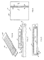
- Fig. 1 indicated generally at 20, is a read/write head/flexure/conductor structure constructed in accordance with the present invention.
- Structure 20 herein has an overall length A of about 0.3-inches, and overall width B of about 0.006-inches, a thickness C along most of its length of about 0.001-inches, and a somewhat greater thickness D of about 0.002-inches forming an enlargement adjacent its left end in Fig. 1, which end may be thought of as the read/write working end of the structure.
- a probe-type head for perpendicular recording with this head including a main pole 22, a yoke 24, a back-gap stud 26, and a flux-return yoke 28.
- these components are magnetically coupled to form a low-reluctance path, terminating in a high-reluctance gap 30 between main pole 22 and the end of return yoke 28.
- This return yoke may be made preferably somewhat wider than yoke 24 to provide a very large area of flux-coupling and a low-reluctance path to the soft magnetic underlayer of the recording medium.
- such a medium is shown generally at 32 including the just-referred-to soft magnetic underlayer 32 a covered with a high-coercivity, perpendicularly oriented recording layer 32 b .
- the direction of motion of medium 32 relative to the head is indicated by arrow 31.
- the magnetic pole structure just generally described is formed in a manner which will be outlined later as a structure embedded within an elongate, dielectric flexure body 34 which is made herein, for example, of aluminum oxide.
- dielectric flexure body 34 which is made herein, for example, of aluminum oxide.
- a helix coil 36 Inductively coupled to yoke 24 in structure 20 is a helix coil 36, also formed in a manner which will be described shortly, with the ends of this coil connecting through lead conductors 38, 40 to bonding pads 42.
- structure 20 includes a form of thin film, ring-type head for recording on longitudinally oriented media, i.e., with an easy axis of magnetization in this plane of the media.
- poles 44, 46 which are relatively thick (in order to avoid pole tip saturation) with their lower extremities substantially coplanar so as to be in close proximity to the surface of an underlying recording medium.
- Gap 48 which exists between these poles is made very small in order to afford good linear bit resolution in signal reproduction. It is this dimension which determines the linear bit resolution in signal reproduction. Most of the flux, produced by current flow in the helix coil, bridges directly across gap 48, with only a small part fringing out to the medium, thus limiting the field intensity in the record mode. For this reason, it is necessary to restrict the throat height of gap 48 (the space where poles 44, 46 confront and parallel one another) so as to cause more of the flux to encompass the medium. As a rule of thumb for thin-film, ring-type heads, the throat height is held to one or two times the gap thickness in order to provide sufficiently high field intensity for recording on high coercivity media.
- gap 48 may be about 0.5-micrometers, thereby enabling linear bit resolution of about 20,000-flux-reversals-per-inch, and restricting throat height to about 1-micrometer. Higher recording densities necessitate still more precise control of throat height in the lapping process.
- gap 30 in the probe type head is made relatively large so that very little flux in the magnetic circuit fringes across this gap. Consequently, virtually all of the flux from the tip of pole 22 is effective in magnetizing the recording layer in the medium, and there is no similar throat height restriction.
- pole 22 is routinely made about 5- to about 10-micrometers without deleterious effect on recording and reproducing performance, though pole tip saturation may become a problem as pole thickness is reduced below about 0.5-micrometers. From this analysis, it will be apparent that probe head recording on two-layer perpendicular media offers great advantage over thin-film ring-head recording on longitudinal media in regard to the ease of head manufacture and tolerance for head wear as head-media separation is reduced, ultimately to continuous sliding contact.
- yoke 50 The remainder of the magnetic structure shown in Fig. 5 includes a yoke 50, a back-gap stud 52, and a return yoke 54.
- Inductively coupled to yoke 50 is a helix coil 56 which is similar to previously mentioned coil 36.
- the ends of coil 56 (not shown) connect to appropriate bonding pads, like pads 42, through connecting conductors, like previously mentioned conductors 38, 40.
- the unitary, integrated character of the read/write structures illustrated and discussed so far have been achieved in what might be thought of as an atom-by-atom construction process.
- One of the most important constituents of the present invention is that sputtered aluminum oxide (or other similar inorganic materials), which is used to form the main, elongate embedding flexure body for the entire structure, is characterized by a high degree of elasticity and structural integrity. This characteristic plays a significant role in the ability to offer such a small-dimension (micro), low-mass (about 100-micrograms) read/write structure.
- the structures shown herein are so significantly reduced in size and mass, that experience has shown that they can be used for direct, continuous, sliding contact operation with a recording medium, virtually free from catastrophic wear.
- a key feature of the present invention lies in the fact that the entire microhead/flexure/connector complex is fabricated as an integral unit, utilizing thin-film and photolithographic technology which is widely known by those skilled in the art.
- the entire structure of the present invention is fabricated atom-by-atom employing conventional thin-film deposition and etching processes, e.g., sputtering, vapor deposition, plating, chemical vapor deposition, ion beam deposition and etching, etc., accompanied by well known photo-patterning of the magnetic, electrical and structural parts.
- the magnetic head structure employed herein becomes, in a sense, an extension of the thin-film reed flexure, and is of comparable thickness. Employment of a helical coil structure winding around a magnetic yoke enables a very significant reduction in the physical width of the overall head structure, and more significantly, in the inductance and resistance of the head and corresponding cross-talk sensitivity. Thin-film deposition of the electrical leads within the flexure structure eliminates the need for bonding twisted-pair conductors as is required in conventional current practice.
- a square wafer 58 which may be a polished flat wafer of silicon or ceramic, e.g. barium titanate, serves as a substrate for the deposition and patterning of all material which makes up structure 20 in Figs. 1, 2 and 3.
- Fig. 7 is a fragmentary section view taken generally along line 7-7 in Fig. 6, illustrating the various layers that are formed during the construction process to make up read/write structure 20.
- the upper surface 20 a in the structure is what is formed first, and is the portion of the structure which lies most closely adjacent the upper surface of wafer 58 in Fig. 6.
- Thin films of titanium 60 and copper 62 are sputtered onto the upper surface of wafer 58, with the former serving as an adhesion layer, and the latter as an electrically conducting electro-plating base.
- a copper layer 64 about 5- to about 25-micrometers thick, is electroplated over film 62, and polished flat to a smooth, bright finish.
- Photoresist is then patterned, forming a mask through which additional copper is plated to a thickness of about 6- to about 10-micrometers to result, after stripping of the photoresist, in the parallel copper stripes 66.
- Photoresist is now patterned with reference to edge 58 a (see Fig. 6) of wafer 58, and about 6- to about 10-micrometers of gold is plated through this pattern to form previously mentioned bonding pads 42 (not shown in Fig. 7).
- a titanium adhesion layer 68 is then sputtered over this surface, followed immediately by sputtering of an aluminum oxide layer 70 to a thickness of about 6- to about 10-micrometers.
- the resulting surface is now lapped and polished to expose stripes 66 and bonding pads 42, and to form a smooth, plane surface.
- a titanium adhesion layer 72 and a plating base 74 are sputtered over this surface, and photoresist is patterned through which about 2- to about 4-micrometers of copper are plated, thereby forming the bottom conductors 76 of previously mentioned helix coil 36.
- Fig. 7 as the bottom conductors of the helix coil, these appear as the top conductors in the coil as illustrated in Fig. 2.
- This same layer forms previously mentioned conductors 38, 40, and gives added height to stripes 66.
- Photoresist is then stripped, and again formed and patterned to enable subsequent plating of copper several micrometers thick through the photoresist mask to form, after etching exposed parts of plating base 74 and titanium layer 72, electrical via connections 78, as well as additional copper on top of stripes 66.
- a titanium adhesion layer 80 is then sputtered onto the surface, and subsequently etched through a photoresist mask to isolate, electrically, conductors 38, 40, all vias 78, and coil conductors 76.
- an aluminum oxide film 82 is sputtered to a thickness of several micrometers, and lapped and polished to expose vias 78 and stripes 66, and again form a smooth, plane surface.
- a nickel-iron permalloy layer 88 is electroplated through a photoresist mask, and in the presence of a strong magnetic field, to a thickness of about 2- to about 3-micrometers thick, to form previously mentioned yoke 24 with a transverse easy axis of magnetization. This step also extends the heights of vias 78 and stripes 66.
- the magnetic components in structure 20 may be made from various alternative materials, e.g., cobalt-iron, cobalt-zirconium, iron-nitride, etc., and by various alternative deposition means, e.g., sputtering, vapor deposition, chemical vapor deposition, etc.
- Photoresist is now stripped and a new photoresist mask is created, through which nickel-iron layer 90 is plated about 4- to about 6-micrometers thick, and again in an appropriate magnetic field, on top of vias 78 and stripes 66, forming the base of previously mentioned back-gap stud 26.
- the exposed areas of layer 84 and base 86 are etched away, and about 6- to about 8-micrometers of aluminum oxide, layer 92, is sputtered over the surface and again lapped and polished to a plane surface, exposing vias 78, the back-gap stud, and stripes 66.
- the thickness of flexure body 34 formed of aluminum oxide, is gradually increasing in this sequence of depositions, and that the width of the flexure body is limited by the spacing between stripes 66.
- a titanium adhesion layer 94 and a copper plating base layer 96 are sputtered on the now exposed surface, and about 2- to about 4-micrometers of copper are plated through a photoresist mask, thereby to form conductors 98 which interconnect vias 78 and complete the fabrication of the helix coil, and the connection to the heretofore isolated conductors 38, 40.
- a new thick photoresist mask is prepared, through which about 20- to about 30-micrometers of nickel-iron, layer 100, is plated in a magnetic field to form back-gap stud 26, and also to add height to stripes 66.
- films 94, 96 are etched away after stripping the photoresist, and about 35- to about 40-micrometers of aluminum oxide, layer 101, is sputtered over the surface.
- the surface is again lapped and polished flat, exposing back gap stud 26 and stripes 66.
- a titanium adhesion layer 102 and a nickel-iron plating base 104 are sputtered to enable a nickel-iron film 106, about 2- to about 4-micrometers thick, to be plated in an appropriate magnetic field in a photoresist mask to create previously mentioned return yoke 54.
- This photoresist mask is then stripped and replaced with a new mask, through which about 15- to about 20-micrometers of nickel-iron, layer 108, is plated on top of stripes 66.
- the exposed areas of layers 102, 104 are etched away, and about 15- to about 20-micrometers of aluminum oxide, layer 110, is sputtered into place, after which it is lapped flat to expose stripes 66.
- the surface of aluminum oxide is etched through a photoresist mask to a depth of about 10- to about 15-micrometers, thereby to define the thickness of flexure body 34 with the enlargement or step in the surface topography which is present in the region of gap 30. This etching step also partially exposes the sides of stripes 66.
- Scribe cuts 112 about 50- to about 100-micrometers deep, and about 100- to about 150-micrometers wide, are made on the back side of wafer 58 with reference to edge 58 a , thereby creating a shallow notch opposite bonding pads 42, as is shown in Fig. 11.
- Saw cuts 114 are now made, dividing wafer 58 into bars 116, exposing the ends of yoke 24, as shown in Fig. 8, but not exposing bonding pads 42 or conductors 38, 40. Bars 116 are assembled and held in a fixture 118 (see Figs. 9 and 10) with epoxy 120, with the ends of yokes 24 exposed and co-planer with the surface of fixture 118.
- the epoxy fills previously mentioned notches, or scribe cuts, 112.
- a soft magnetic film 122 (see Figs. 12 and 13), having a high saturation magnetization, is sputtered to the desired thickness of previously mentioned pole 22 in the presence of a strong magnetic field so that the easy axis of magnetization is parallel to the lengths of bars 116, as indicated by arrows 124 in Fig. 12.
- Film 122 is then patterned, preferably by ion milling through a photoresist mask, to form previously mentioned poles 22 which join with the exposed ends of yokes 24, as shown in Figs. 12 and 13.
- a passivation layer 126 of aluminum oxide, about 2- to about 4-micrometers thick is sputtered over the surface.
- Photoresist is patterned and layer 126 is etched, leaving aluminum oxide covered poles 22 as seen in Figs. 12 and 13.
- Fixture 118 is then immersed in a solvent to dissolve the epoxy and to free bars 116.
- the bars are then immersed in an etch bath which dissolves the copper and nickel-iron in stripes 66, and copper layer 64 underneath the flexure body 34, thereby completing the fabrication of the structure of the invention.
- run-in lapping serves to expose the tip of pole 22.
- Fig. 14 there is shown, fragmentarily and generally at 128 a multihead array of individual, independently flexible, head/flexure/conductor structures arranged as fingers, such as those shown at 128 a , 128 b , 128 c , which extend from and are joined through a common support base indicated generally at 128 d .
- Each of these finger-like structures, except where the same joins with base 128 d may have the same internal construction as either of the structures shown in Figs. 1 or 5.
Landscapes
- Engineering & Computer Science (AREA)
- Manufacturing & Machinery (AREA)
- Magnetic Heads (AREA)
- Supporting Of Heads In Record-Carrier Devices (AREA)
- Adjustment Of The Magnetic Head Position Track Following On Tapes (AREA)
Applications Claiming Priority (2)
| Application Number | Priority Date | Filing Date | Title |
|---|---|---|---|
| US441716 | 1989-11-27 | ||
| US07/441,716 US5041932A (en) | 1989-11-27 | 1989-11-27 | Integrated magnetic read/write head/flexure/conductor structure |
Publications (3)
| Publication Number | Publication Date |
|---|---|
| EP0430407A2 true EP0430407A2 (fr) | 1991-06-05 |
| EP0430407A3 EP0430407A3 (en) | 1992-09-09 |
| EP0430407B1 EP0430407B1 (fr) | 1996-12-11 |
Family
ID=23754007
Family Applications (1)
| Application Number | Title | Priority Date | Filing Date |
|---|---|---|---|
| EP90310697A Expired - Lifetime EP0430407B1 (fr) | 1989-11-27 | 1990-09-28 | Structure magnétique intégrée de tête de lecture/d'écriture/dispositif de flexion/conducteur |
Country Status (6)
| Country | Link |
|---|---|
| US (2) | US5041932A (fr) |
| EP (1) | EP0430407B1 (fr) |
| JP (1) | JP2790914B2 (fr) |
| AT (1) | ATE146293T1 (fr) |
| CA (1) | CA2026871C (fr) |
| DE (1) | DE69029371D1 (fr) |
Cited By (14)
| Publication number | Priority date | Publication date | Assignee | Title |
|---|---|---|---|---|
| EP0508565A2 (fr) * | 1991-04-10 | 1992-10-14 | Censtor Corporation | Tête résistante à l'usure pour lire et écrire avec contact sur un support magnétique |
| EP0517980A1 (fr) * | 1991-06-11 | 1992-12-16 | Censtor Corporation | Structure intégrée de tête magnétique de lecture/écriture, d'élément de flexion et de conducteur |
| EP0540283A2 (fr) * | 1991-10-28 | 1993-05-05 | Censtor Corporation | Support flexible à la cardan pour micro-tête, conducteur et dispositif |
| EP0540282A2 (fr) * | 1991-10-28 | 1993-05-05 | Censtor Corporation | Disque dur à format variable pour système de stockage magnétique pour information numérique des améliorations localisées de lecture/écriture |
| JPH05135524A (ja) * | 1991-06-10 | 1993-06-01 | Fujitsu Ltd | 磁気デイスク装置 |
| JPH05135525A (ja) * | 1991-06-11 | 1993-06-01 | Fujitsu Ltd | 磁気デイスク装置 |
| EP0568257A1 (fr) * | 1992-04-30 | 1993-11-03 | International Business Machines Corporation | Tête pour transférer les données |
| EP0576680A1 (fr) * | 1992-01-20 | 1994-01-05 | Fujitsu Limited | Ensemble tete magnetique, sa production et unite de disque magnetique |
| EP0580442A2 (fr) * | 1992-07-23 | 1994-01-26 | Censtor Corporation | Structure intégrée de tête magnétique de lecture/écriture, d'élément de flexion et de conducteurs |
| EP0583921A1 (fr) * | 1992-08-19 | 1994-02-23 | International Business Machines Corporation | Structure unitaire de transducteur magnétique et de suspension pour l'opération longitudinal |
| EP0584983A1 (fr) * | 1992-08-25 | 1994-03-02 | International Business Machines Corporation | Structure unitaire de transducteur magnétique et de suspension |
| EP0613121A1 (fr) * | 1993-02-26 | 1994-08-31 | International Business Machines Corporation | Dispositif de mémorisation magnétique rotatif |
| CN1064161C (zh) * | 1993-08-28 | 2001-04-04 | 国际商业机器公司 | 用于纵向记录的组合式薄膜磁头和悬浮系统及其制造方法 |
| CN1068448C (zh) * | 1993-03-15 | 2001-07-11 | 国际商业机器公司 | 用于垂直记录的一体化传感器一悬架组件 |
Families Citing this family (88)
| Publication number | Priority date | Publication date | Assignee | Title |
|---|---|---|---|---|
| US5476131A (en) * | 1989-11-27 | 1995-12-19 | Censtor Corporation | Unitary micro-flexure structure and method of making same |
| US6320725B1 (en) * | 1989-11-27 | 2001-11-20 | Censtor Corporation | Hard disk drive having ring head with predominantly perpendicular media fields |
| US6411470B1 (en) * | 1991-10-28 | 2002-06-25 | Censtor Corporation | Durable, low-vibration, dynamic-contact hard disk drive system |
| US6600631B1 (en) * | 1989-11-27 | 2003-07-29 | Censtor Corp. | Transducer/flexure/conductor structure for electromagnetic read/write system |
| US20020176210A1 (en) * | 1989-11-27 | 2002-11-28 | Hamilton Harold J. | Durable, low-vibration, dynamic-contact hard disk drive system |
| US5111351A (en) * | 1989-11-27 | 1992-05-05 | Censtor Corp. | Integrated magnetic read/write head/flexure/conductor structure |
| US6493191B1 (en) * | 1989-11-27 | 2002-12-10 | Censtor Corporation | Planar magnetic ring head for contact recording with a rigid disk |
| US5453315A (en) * | 1989-11-27 | 1995-09-26 | Censtor Corp. | Unitary micro-flexure structure and method of making same |
| US5483025A (en) * | 1989-11-27 | 1996-01-09 | Censtor Corporation | Unitary micro-flexure structure |
| JPH0485771A (ja) * | 1990-07-27 | 1992-03-18 | Hitachi Ltd | 磁気記録装置 |
| DE69232468T2 (de) * | 1991-06-10 | 2002-07-11 | Fujitsu Ltd., Kawasaki | Magnetplattenantrieb |
| KR960001251B1 (ko) * | 1991-06-10 | 1996-01-24 | 후지쓰 가부시끼가이샤 | 자기디스크드라이브 및 그 조립방법 |
| EP0569593B1 (fr) * | 1991-11-22 | 1999-09-08 | Fujitsu Limited | Dispositif a disque |
| JP2673624B2 (ja) * | 1992-01-20 | 1997-11-05 | 富士通株式会社 | 一体型薄膜ヘッド |
| JP2587162B2 (ja) * | 1992-01-22 | 1997-03-05 | 富士通株式会社 | 磁気ディスク装置のヘッドアーム |
| JP2683177B2 (ja) * | 1992-01-22 | 1997-11-26 | 富士通株式会社 | 集積型一体化磁気ヘッドの製造方法及びアームへの取付方法 |
| US5396388A (en) * | 1992-02-27 | 1995-03-07 | Censtor Corp. | Compact, high-speed, rotary actuator and transducer assembly with reduced moment of inertia and mass-balanced structural overlap with drive motor and organizing method for the same |
| JP3303336B2 (ja) * | 1992-06-17 | 2002-07-22 | 株式会社日立製作所 | 磁気ディスク装置 |
| US5302434A (en) * | 1992-08-07 | 1994-04-12 | International Business Machines Corporation | Magnetic recording disk for contact recording |
| US5307223A (en) * | 1992-08-07 | 1994-04-26 | International Business Machines Corporation | Magnetic recording disk file for contact recording |
| US6341415B2 (en) | 1992-08-31 | 2002-01-29 | Fujitsu Limited | Method for assembling a magnetic head assembly and magnetic disk drive using bonding balls connecting magnetic head terminals to wiring terminals |
| US5986852A (en) * | 1992-10-19 | 1999-11-16 | International Business Machines Corporation | High capacity, high performance low profile disk drive |
| US5608592A (en) * | 1992-10-29 | 1997-03-04 | Fujitsu Limited | Head actuator |
| JPH06150257A (ja) * | 1992-10-30 | 1994-05-31 | Fujitsu Ltd | 薄膜磁気ヘッドおよびその製造方法 |
| US5644450A (en) * | 1992-10-30 | 1997-07-01 | Fujitsu Limited | Magnetic head assembly with thin-film magnetic head and flexible support member |
| US6084743A (en) * | 1992-12-14 | 2000-07-04 | Maxtor Corporation | Magnetic recorder apparatus with reduced debris accumlation on the recorder head and slider |
| US5396383A (en) * | 1992-12-29 | 1995-03-07 | International Business Machines | Integral lubricating fluid delivery system for a flying head in a magnetic disk storage system |
| CN1058799C (zh) * | 1993-01-08 | 2000-11-22 | 国际商业机器公司 | 薄膜磁传感器和悬架组件及其制造方法以及磁盘驱动组件 |
| JPH06236674A (ja) * | 1993-02-10 | 1994-08-23 | Fujitsu Ltd | 磁気ディスク装置 |
| US5455730A (en) * | 1993-02-18 | 1995-10-03 | International Business Machines Corporation | Contact magnetic recording disk file with a magnetoresistive read sensor |
| US5486967A (en) * | 1993-03-15 | 1996-01-23 | Kabushiki Kaisha Toshiba | Magnetic disk memory system |
| US5734519A (en) * | 1993-03-25 | 1998-03-31 | International Business Machines Corporation | Contact magnetic recording disk file with improved head assembly |
| US5327638A (en) * | 1993-08-20 | 1994-07-12 | Maxtor Corporation | Method of making a vertical recording head for contact and near contact magnetic recording |
| US5486968A (en) * | 1993-11-10 | 1996-01-23 | International Business Machines Corporation | Method and apparatus for simultaneous write head planarization and lead routing |
| US5367417A (en) * | 1993-12-16 | 1994-11-22 | International Business Machines Corporation | Disk drive with flow-by chemical breather filter |
| US5859748A (en) * | 1993-12-22 | 1999-01-12 | Kabushiki Kaisha Toshiba | Magnetic head device including an improved slider shape |
| US5462636A (en) * | 1993-12-28 | 1995-10-31 | International Business Machines Corporation | Method for chemically scribing wafers |
| US5521774A (en) * | 1994-03-18 | 1996-05-28 | Cartesian Data, Inc. | Memory storage module for storing and accessing |
| US5687046A (en) * | 1994-05-25 | 1997-11-11 | Maxtor Corporation | Vertical recording using a tri-pad head |
| US5805375A (en) * | 1994-08-01 | 1998-09-08 | International Business Machines Corporation | Wobble motor microactuator for fine positioning and disk drive incorporating the microactuator |
| US5909346A (en) * | 1994-08-26 | 1999-06-01 | Aiwa Research & Development, Inc. | Thin magnetic film including multiple geometry gap structures on a common substrate |
| US5563754A (en) * | 1994-08-26 | 1996-10-08 | Aiwa Research And Development, Inc. | Thin film magnetic head including a durable wear layer and gap structure |
| JPH08171712A (ja) * | 1994-08-26 | 1996-07-02 | Aiwa Co Ltd | 側面露出型薄膜磁気ヘッド並びにその製造方法 |
| US5801909A (en) * | 1994-08-26 | 1998-09-01 | Aiwa Research And Development, Inc. | Thin film magnetic head including durable wear layer and non-magnetic gap structures |
| US5748417A (en) * | 1994-08-26 | 1998-05-05 | Aiwa Research And Development, Inc. | Thin film magnetic head including layered magnetic side poles |
| US5673474A (en) * | 1994-08-26 | 1997-10-07 | Aiwa Research And Development, Inc. | Method of fabricating a thin film magnetic head including layered magnetic side poles |
| US5754377A (en) * | 1994-08-26 | 1998-05-19 | Aiwa Research And Development, Inc. | Thin film magnetic head including an elevated gap structure |
| US5490028A (en) * | 1994-08-26 | 1996-02-06 | Aiwa Research And Development, Inc. | Thin film magnetic head including an integral layered shield structure |
| US5544774A (en) * | 1994-08-26 | 1996-08-13 | Aiwa Research And Development, Inc. | Method of eliminating pole recession in a thin film magnetic head |
| US6091581A (en) * | 1994-08-26 | 2000-07-18 | Aiwa Co., Ltd. | Thin film magnetic head including a separately deposited diamond-like carbon gap structure and magnetic control wells |
| US5539596A (en) * | 1994-12-29 | 1996-07-23 | International Business Machines Corporation | Integrated suspension, actuator arm and coil assembly with common structural support layer |
| US5606474A (en) * | 1995-01-17 | 1997-02-25 | Latsu, Inc. | High density disk drive with accelerated disk access |
| US5621594A (en) * | 1995-02-17 | 1997-04-15 | Aiwa Research And Development, Inc. | Electroplated thin film conductor coil assembly |
| JP2865012B2 (ja) * | 1995-02-27 | 1999-03-08 | 日本電気株式会社 | 磁気ヘッド装置及びその製造方法 |
| US6804085B1 (en) | 1995-03-21 | 2004-10-12 | Seagate Technology, Llc | Hard drive system interface between a disk surface and a transducer contacting the surface during communication |
| JP3139323B2 (ja) * | 1995-04-07 | 2001-02-26 | 株式会社日立製作所 | 磁気ディスク装置及びスライダ |
| US6760193B1 (en) * | 1995-04-07 | 2004-07-06 | Hitachi Global Storage Technologies Japan, Ltd. | Magnetic head gimbal assembly and magnetic disk unit |
| US5898540A (en) * | 1995-05-25 | 1999-04-27 | Hitachi, Ltd | Magnetic head and slider configuration for contact recording having a plurality of tapered surfaces |
| US5608591A (en) * | 1995-06-09 | 1997-03-04 | International Business Machines Corporation | Integrated head-electronics interconnection suspension for a data recording disk drive |
| JPH0916932A (ja) * | 1995-06-27 | 1997-01-17 | Hitachi Ltd | 磁気ヘッド支持機構およびその製造方法ならびに磁気ディスク装置 |
| US6195232B1 (en) * | 1995-08-24 | 2001-02-27 | Torohead, Inc. | Low-noise toroidal thin film head with solenoidal coil |
| US5661618A (en) * | 1995-12-11 | 1997-08-26 | International Business Machines Corporation | Magnetic recording device having a improved slider |
| US5742452A (en) * | 1996-01-10 | 1998-04-21 | International Business Machines Corporation | Low mass magnetic recording head and suspension |
| US6069015A (en) * | 1996-05-20 | 2000-05-30 | Aiwa Research And Development, Inc. | Method of fabricating thin film magnetic head including durable wear layer and non-magnetic gap structure |
| US5805382A (en) * | 1996-06-21 | 1998-09-08 | International Business Machines Corporation | Integrated conductor magnetic recording head and suspension having cross-over integrated circuits for noise reduction |
| US5701218A (en) * | 1996-07-03 | 1997-12-23 | Seagate Technology, Inc. | Flex on suspension design minimizing sensitivities to environmental stresses |
| US5753092A (en) * | 1996-08-26 | 1998-05-19 | Velocidata, Inc. | Cylindrical carriage sputtering system |
| US6147839A (en) * | 1996-12-23 | 2000-11-14 | Hutchinson Technology, Inc. | Head suspension with outriggers extending across a spring region |
| US5822153A (en) * | 1997-01-03 | 1998-10-13 | Censtor Corp. | Hard disk drive having contact write and recessed magnetorestive read head |
| US6078468A (en) * | 1997-05-01 | 2000-06-20 | Fiske; Orlo James | Data storage and/or retrieval methods and apparatuses and components thereof |
| JP2950301B2 (ja) | 1997-11-21 | 1999-09-20 | 日本電気株式会社 | 磁気ディスク装置 |
| US5924187A (en) | 1998-01-06 | 1999-07-20 | Hutchinson Technology Incorporated | Integrated lead head suspension assembly having an etched laminated load beam and flexure with deposited conductors |
| US5871655A (en) * | 1998-03-19 | 1999-02-16 | International Business Machines Corporation | Integrated conductor magnetic recording head and suspension having cross-over integrated circuits for noise reduction |
| US5995324A (en) * | 1998-05-21 | 1999-11-30 | Maxtor Corporation | Pseudo-contact slider with recessed magneto-resistive transducer |
| US6414822B1 (en) | 1998-06-11 | 2002-07-02 | Seagate Technology Llc | Magnetic microactuator |
| US6507463B1 (en) | 1999-06-11 | 2003-01-14 | Seagate Technology, Inc. | Micro disc drive employing arm level microactuator |
| US6654205B1 (en) | 1999-11-01 | 2003-11-25 | Maxtor Corporation | Air bearing surface for reducing pressure gradients |
| US6735049B1 (en) | 2002-03-28 | 2004-05-11 | Mark A. Lauer | Electromagnetic heads, flexures and gimbals formed on and from a wafer substrate |
| US6816339B1 (en) * | 2000-01-10 | 2004-11-09 | Seagate Technology Llc | Perpendicular magnetic recording head with longitudinal magnetic field generator to facilitate magnetization switching |
| US6707631B1 (en) | 2000-03-20 | 2004-03-16 | Maxtor Corporation | Flying-type disk drive slider with wear pad |
| US7193805B1 (en) | 2000-03-20 | 2007-03-20 | Maxtor Corporation | Flying-type disk drive slider with micropad |
| US6717770B1 (en) | 2000-03-24 | 2004-04-06 | Seagate Technology Llc | Recording head for applying a magnetic field perpendicular to the magnetizations within magnetic storage media |
| US6501619B1 (en) * | 2000-04-27 | 2002-12-31 | Shipley Company, L.L.C. | Inductive magnetic recording head having inclined magnetic read/write pole and method of making same |
| US7248444B1 (en) | 2000-07-21 | 2007-07-24 | Lauer Mark A | Electromagnetic heads, flexures, gimbals and actuators formed on and from a wafer substrate |
| US6958885B1 (en) * | 2000-12-21 | 2005-10-25 | Western Digital (Fremont), Inc. | Insulation layer structure for inductive write heads and method of fabrication |
| US7289302B1 (en) | 2001-10-04 | 2007-10-30 | Maxtor Corporation | On slider inductors and capacitors to reduce electrostatic discharge damage |
| US7289285B2 (en) * | 2002-10-24 | 2007-10-30 | Charles Frederick James Barnes | Information storage systems |
| JPWO2006008799A1 (ja) * | 2004-07-16 | 2008-05-01 | 株式会社シーアンドエヌ | 磁気センサ組立体、地磁気検出装置、素子組立体および携帯端末装置 |
Citations (4)
| Publication number | Priority date | Publication date | Assignee | Title |
|---|---|---|---|---|
| US4652956A (en) * | 1983-12-23 | 1987-03-24 | Siemens Aktiengesellschaft | Thin-film magnetic head for perpendicular magnetization having a ring shaped magnetic read/write conducting body and write coil winding arranged outside the conducting body |
| US4684348A (en) * | 1986-01-09 | 1987-08-04 | Raynor Grace M | Communications process and apparatus |
| US4789914A (en) * | 1986-10-28 | 1988-12-06 | International Business Machines Corporation | Thin film magnetic read-write head/arm assemblies |
| WO1989000327A1 (fr) * | 1987-07-01 | 1989-01-12 | Digital Equipment Corporation | Tete de lecture/ecriture a couche mince solenoidale pour memoire d'ordinateur de grande capacite, et son procede de fabrication |
Family Cites Families (28)
| Publication number | Priority date | Publication date | Assignee | Title |
|---|---|---|---|---|
| US3805290A (en) * | 1972-10-24 | 1974-04-16 | Memorex Corp | Recording head flexure |
| US3864748A (en) * | 1973-07-23 | 1975-02-04 | Sperry Rand Corp | Magnetic disk memory |
| US3919717A (en) * | 1974-07-24 | 1975-11-11 | Ibm | Wear-resistant surface for magnetic heads consisting of diamond particles |
| US4028734A (en) * | 1975-05-19 | 1977-06-07 | American Magnetics Corporation | Plural magnetic head assembly with independently supporting structure |
| US4131924A (en) * | 1977-10-03 | 1978-12-26 | Burroughs Corporation | Flexure mounted magnetic head positioner for high-speed translation |
| US4167765A (en) * | 1978-07-27 | 1979-09-11 | International Business Machines Corporation | Transducer suspension mount apparatus |
| US4245267A (en) * | 1979-06-01 | 1981-01-13 | New World Computer Company, Inc. | Suspension device for magnetic transducers |
| JPS5674812A (en) * | 1979-11-26 | 1981-06-20 | Nippon Telegr & Teleph Corp <Ntt> | Magnetic head assembly |
| US4422115A (en) * | 1980-02-29 | 1983-12-20 | Digital Equipment Corporation | Lightweight dual head support assembly for magnetic disk drives |
| JPS5766572A (en) * | 1980-10-09 | 1982-04-22 | Mitsubishi Electric Corp | Magnetic head moving device of both-sided flexible disk storage device |
| US4363045A (en) * | 1980-10-20 | 1982-12-07 | New World Computer Company, Inc. | Magnetic transducer suspension device |
| JPS57117117A (en) * | 1981-01-09 | 1982-07-21 | Matsushita Electric Ind Co Ltd | Thin film magnetic head |
| US4456936A (en) * | 1982-01-18 | 1984-06-26 | International Business Machines Corporation | Cantilevered transducer carriage |
| US4517616A (en) * | 1982-04-12 | 1985-05-14 | Memorex Corporation | Thin film magnetic recording transducer having embedded pole piece design |
| US4535374A (en) * | 1982-11-04 | 1985-08-13 | Amcodyne Incorporated | Whitney-type head loading/unloading apparatus |
| HU188511B (en) * | 1983-11-11 | 1986-04-28 | Budapesti Radiotechnikai Gyar,Hu | Magnetic reading and/or writing head |
| FR2559297B1 (fr) * | 1984-02-03 | 1990-01-12 | Commissariat Energie Atomique | Nouveau patin de vol pour tetes magnetiques d'enregistrement |
| US4654737A (en) * | 1984-03-26 | 1987-03-31 | Tandon Corporation | Magnetic disk memory head carriage assembly employing backlash-free rack and pinion drive mechanism |
| JPH0351778Y2 (fr) * | 1984-08-31 | 1991-11-07 | ||
| CN1008844B (zh) * | 1984-10-02 | 1990-07-18 | 株式会社日立制作所 | 薄膜磁头滑块和制备薄膜磁头滑块材料的方法 |
| JPH081688B2 (ja) * | 1984-10-05 | 1996-01-10 | 富士写真フイルム株式会社 | 薄膜磁気ヘツドおよびその製造方法 |
| JPS61104313A (ja) * | 1984-10-22 | 1986-05-22 | Sharp Corp | 薄膜磁気ヘツド装置 |
| US4829395A (en) * | 1985-09-06 | 1989-05-09 | Warren Coon | Load beam/assembly |
| US4703376A (en) * | 1985-09-23 | 1987-10-27 | Lapine Technology | Apparatus for loading and retracting magnetic head in a disk drive |
| US4703375A (en) * | 1985-11-22 | 1987-10-27 | Chan Industries, Inc. | Low mass tricomplaint recording device for double sided floppy disk media |
| FR2604021B1 (fr) * | 1986-09-17 | 1988-10-28 | Commissariat Energie Atomique | Procede de realisation de tetes magnetiques en couches minces et a structure planaire et tete obtenue par ce procede |
| FR2611970B1 (fr) * | 1987-03-06 | 1989-05-26 | Thomson Csf | Procede de realisation d'une tete magnetique en couches minces et application a une tete d'enretistrement/lecture |
| US4819091A (en) * | 1987-04-30 | 1989-04-04 | International Business Machines Corporation | High speed magnetic disk contact recording system |
-
1989
- 1989-11-27 US US07/441,716 patent/US5041932A/en not_active Expired - Lifetime
-
1990
- 1990-09-28 EP EP90310697A patent/EP0430407B1/fr not_active Expired - Lifetime
- 1990-09-28 AT AT90310697T patent/ATE146293T1/de not_active IP Right Cessation
- 1990-09-28 DE DE69029371T patent/DE69029371D1/de not_active Expired - Lifetime
- 1990-10-03 CA CA002026871A patent/CA2026871C/fr not_active Expired - Fee Related
- 1990-10-18 JP JP2281717A patent/JP2790914B2/ja not_active Expired - Lifetime
-
1991
- 1991-06-11 US US07/710,891 patent/US5163218A/en not_active Expired - Lifetime
Patent Citations (4)
| Publication number | Priority date | Publication date | Assignee | Title |
|---|---|---|---|---|
| US4652956A (en) * | 1983-12-23 | 1987-03-24 | Siemens Aktiengesellschaft | Thin-film magnetic head for perpendicular magnetization having a ring shaped magnetic read/write conducting body and write coil winding arranged outside the conducting body |
| US4684348A (en) * | 1986-01-09 | 1987-08-04 | Raynor Grace M | Communications process and apparatus |
| US4789914A (en) * | 1986-10-28 | 1988-12-06 | International Business Machines Corporation | Thin film magnetic read-write head/arm assemblies |
| WO1989000327A1 (fr) * | 1987-07-01 | 1989-01-12 | Digital Equipment Corporation | Tete de lecture/ecriture a couche mince solenoidale pour memoire d'ordinateur de grande capacite, et son procede de fabrication |
Cited By (26)
| Publication number | Priority date | Publication date | Assignee | Title |
|---|---|---|---|---|
| EP0508565A2 (fr) * | 1991-04-10 | 1992-10-14 | Censtor Corporation | Tête résistante à l'usure pour lire et écrire avec contact sur un support magnétique |
| EP0508565A3 (en) * | 1991-04-10 | 1993-06-30 | Censtor Corporation | Wear-resistant head for contact reading and writing magnetic media |
| JPH05135524A (ja) * | 1991-06-10 | 1993-06-01 | Fujitsu Ltd | 磁気デイスク装置 |
| EP0517980A1 (fr) * | 1991-06-11 | 1992-12-16 | Censtor Corporation | Structure intégrée de tête magnétique de lecture/écriture, d'élément de flexion et de conducteur |
| JPH05135525A (ja) * | 1991-06-11 | 1993-06-01 | Fujitsu Ltd | 磁気デイスク装置 |
| EP0540283A2 (fr) * | 1991-10-28 | 1993-05-05 | Censtor Corporation | Support flexible à la cardan pour micro-tête, conducteur et dispositif |
| EP0540282A2 (fr) * | 1991-10-28 | 1993-05-05 | Censtor Corporation | Disque dur à format variable pour système de stockage magnétique pour information numérique des améliorations localisées de lecture/écriture |
| EP0540282A3 (en) * | 1991-10-28 | 1993-06-30 | Censtor Corporation | Size-independent, rigid-disk, magnetic digital-information storage system with localized read/write enhancements |
| EP0540283A3 (en) * | 1991-10-28 | 1993-08-11 | Censtor Corporation | Gimbaled micro-head/flexure/conductor assembly and system |
| EP0576680A4 (fr) * | 1992-01-20 | 1994-02-16 | Fujitsu Limited | |
| EP0576680A1 (fr) * | 1992-01-20 | 1994-01-05 | Fujitsu Limited | Ensemble tete magnetique, sa production et unite de disque magnetique |
| US6141182A (en) * | 1992-01-20 | 2000-10-31 | Fujitsu Limited | Magnetic head assembly with contact-type head chip mounting and electrically connecting arrangements |
| US6002550A (en) * | 1992-01-20 | 1999-12-14 | Fujitsu, Ltd. | Magnetic head assembly with ball member for electrically connecting the slider member and the suspension member |
| US5761005A (en) * | 1992-04-30 | 1998-06-02 | International Business Machines Corporation | Combination transducer/slider/suspension |
| EP0568257A1 (fr) * | 1992-04-30 | 1993-11-03 | International Business Machines Corporation | Tête pour transférer les données |
| USRE36538E (en) * | 1992-04-30 | 2000-02-01 | International Business Machines Corporation | Combination transducer/slider/suspension and method for making |
| US5528819A (en) * | 1992-04-30 | 1996-06-25 | International Business Machines Corporation | Combination transducer/slider/suspension and method for making |
| EP0580442A2 (fr) * | 1992-07-23 | 1994-01-26 | Censtor Corporation | Structure intégrée de tête magnétique de lecture/écriture, d'élément de flexion et de conducteurs |
| EP0580442A3 (fr) * | 1992-07-23 | 1994-02-16 | Censtor Corp | |
| EP0583921A1 (fr) * | 1992-08-19 | 1994-02-23 | International Business Machines Corporation | Structure unitaire de transducteur magnétique et de suspension pour l'opération longitudinal |
| US5745979A (en) * | 1992-08-25 | 1998-05-05 | International Business Machines Corporation | Magnetic head for recording with ultra low force |
| EP0584983A1 (fr) * | 1992-08-25 | 1994-03-02 | International Business Machines Corporation | Structure unitaire de transducteur magnétique et de suspension |
| US6271995B1 (en) | 1992-08-25 | 2001-08-07 | International Business Machines Corporation | Magnetic head for recording with ultra low force |
| EP0613121A1 (fr) * | 1993-02-26 | 1994-08-31 | International Business Machines Corporation | Dispositif de mémorisation magnétique rotatif |
| CN1068448C (zh) * | 1993-03-15 | 2001-07-11 | 国际商业机器公司 | 用于垂直记录的一体化传感器一悬架组件 |
| CN1064161C (zh) * | 1993-08-28 | 2001-04-04 | 国际商业机器公司 | 用于纵向记录的组合式薄膜磁头和悬浮系统及其制造方法 |
Also Published As
| Publication number | Publication date |
|---|---|
| CA2026871A1 (fr) | 1991-05-28 |
| EP0430407A3 (en) | 1992-09-09 |
| JPH03178017A (ja) | 1991-08-02 |
| US5041932A (en) | 1991-08-20 |
| EP0430407B1 (fr) | 1996-12-11 |
| ATE146293T1 (de) | 1996-12-15 |
| US5163218A (en) | 1992-11-17 |
| CA2026871C (fr) | 1993-08-17 |
| JP2790914B2 (ja) | 1998-08-27 |
| DE69029371D1 (de) | 1997-01-23 |
Similar Documents
| Publication | Publication Date | Title |
|---|---|---|
| US5041932A (en) | Integrated magnetic read/write head/flexure/conductor structure | |
| US5111351A (en) | Integrated magnetic read/write head/flexure/conductor structure | |
| US5073242A (en) | Method of making integrated magnetic read/write head/flexure/conductor structure | |
| CA2110135C (fr) | Ensemble transducteur-suspension pour l'enregistrement vertical | |
| US6496330B1 (en) | Magnetic write head having a splitcoil structure | |
| US5285340A (en) | Thin film magnetic head with conformable pole tips | |
| US5452166A (en) | Thin film magnetic recording head for minimizing undershoots and a method for manufacturing the same | |
| US6751054B2 (en) | Thin-film magnetic head for perpendicular magnetic recording having main magnetic pole layer on flat surface | |
| JPH09120507A (ja) | 磁気ヘッド・アセンブリ | |
| US5174012A (en) | Method of making magnetic read/write head/flexure/conductor unit(s) | |
| US20060150397A1 (en) | Magnetic read/write head | |
| US6826020B2 (en) | Merged-pole magnetic head having inverted write elements | |
| JP2670341B2 (ja) | 薄膜磁気ヘッド | |
| JPH08171712A (ja) | 側面露出型薄膜磁気ヘッド並びにその製造方法 | |
| US7336445B2 (en) | Conductive stud for magnetic recording devices and method of making the same | |
| US6076252A (en) | Method of manufacturing combination type thin film magnetic head | |
| EP0517980A1 (fr) | Structure intégrée de tête magnétique de lecture/écriture, d'élément de flexion et de conducteur | |
| EP0580442A2 (fr) | Structure intégrée de tête magnétique de lecture/écriture, d'élément de flexion et de conducteurs | |
| US6134078A (en) | High sensitivity, low distortion yoke-type magnetoresistive head | |
| KR0134459B1 (ko) | 테이프레코더의 회전드럼용 헤드조립체 제조방법 | |
| JP3799221B2 (ja) | 薄膜磁気ヘッド及びその製造方法 | |
| JP3231510B2 (ja) | 磁気ヘッド | |
| KR0134457B1 (ko) | 테이프레코더의 회전드럼용 헤드조립체 및 그 제조방법 | |
| KR0134458B1 (ko) | 테이프레코더의 회전드럼용 헤드조립체 제조방법 | |
| KR0134460B1 (ko) | 테이프레코더의 회전드럼용 헤드조립체 및 그 제조방법 |
Legal Events
| Date | Code | Title | Description |
|---|---|---|---|
| PUAI | Public reference made under article 153(3) epc to a published international application that has entered the european phase |
Free format text: ORIGINAL CODE: 0009012 |
|
| AK | Designated contracting states |
Kind code of ref document: A2 Designated state(s): AT BE CH DE DK ES FR GB GR IT LI LU NL SE |
|
| PUAL | Search report despatched |
Free format text: ORIGINAL CODE: 0009013 |
|
| AK | Designated contracting states |
Kind code of ref document: A3 Designated state(s): AT BE CH DE DK ES FR GB GR IT LI LU NL SE |
|
| 17P | Request for examination filed |
Effective date: 19930215 |
|
| 17Q | First examination report despatched |
Effective date: 19940527 |
|
| GRAH | Despatch of communication of intention to grant a patent |
Free format text: ORIGINAL CODE: EPIDOS IGRA |
|
| GRAH | Despatch of communication of intention to grant a patent |
Free format text: ORIGINAL CODE: EPIDOS IGRA |
|
| GRAA | (expected) grant |
Free format text: ORIGINAL CODE: 0009210 |
|
| AK | Designated contracting states |
Kind code of ref document: B1 Designated state(s): AT BE CH DE DK ES FR GB GR IT LI LU NL SE |
|
| PG25 | Lapsed in a contracting state [announced via postgrant information from national office to epo] |
Ref country code: IT Free format text: LAPSE BECAUSE OF FAILURE TO SUBMIT A TRANSLATION OF THE DESCRIPTION OR TO PAY THE FEE WITHIN THE PRE;WARNING: LAPSES OF ITALIAN PATENTS WITH EFFECTIVE DATE BEFORE 2007 MAY HAVE OCCURRED AT ANY TIME BEFORE 2007. THE CORRECT EFFECTIVE DATE MAY BE DIFFERENT FROM THE ONE RECORDED.SCRIBED TIME-LIMIT Effective date: 19961211 Ref country code: ES Free format text: THE PATENT HAS BEEN ANNULLED BY A DECISION OF A NATIONAL AUTHORITY Effective date: 19961211 Ref country code: LI Effective date: 19961211 Ref country code: BE Effective date: 19961211 Ref country code: AT Effective date: 19961211 Ref country code: NL Free format text: LAPSE BECAUSE OF FAILURE TO SUBMIT A TRANSLATION OF THE DESCRIPTION OR TO PAY THE FEE WITHIN THE PRESCRIBED TIME-LIMIT Effective date: 19961211 Ref country code: GR Free format text: LAPSE BECAUSE OF FAILURE TO SUBMIT A TRANSLATION OF THE DESCRIPTION OR TO PAY THE FEE WITHIN THE PRESCRIBED TIME-LIMIT Effective date: 19961211 Ref country code: DK Effective date: 19961211 Ref country code: CH Effective date: 19961211 |
|
| REF | Corresponds to: |
Ref document number: 146293 Country of ref document: AT Date of ref document: 19961215 Kind code of ref document: T |
|
| REF | Corresponds to: |
Ref document number: 69029371 Country of ref document: DE Date of ref document: 19970123 |
|
| PG25 | Lapsed in a contracting state [announced via postgrant information from national office to epo] |
Ref country code: SE Effective date: 19970311 |
|
| PG25 | Lapsed in a contracting state [announced via postgrant information from national office to epo] |
Ref country code: DE Effective date: 19970312 |
|
| ET | Fr: translation filed | ||
| NLV1 | Nl: lapsed or annulled due to failure to fulfill the requirements of art. 29p and 29m of the patents act | ||
| REG | Reference to a national code |
Ref country code: CH Ref legal event code: PL |
|
| PG25 | Lapsed in a contracting state [announced via postgrant information from national office to epo] |
Ref country code: LU Free format text: LAPSE BECAUSE OF NON-PAYMENT OF DUE FEES Effective date: 19970930 |
|
| PLBE | No opposition filed within time limit |
Free format text: ORIGINAL CODE: 0009261 |
|
| STAA | Information on the status of an ep patent application or granted ep patent |
Free format text: STATUS: NO OPPOSITION FILED WITHIN TIME LIMIT |
|
| 26N | No opposition filed | ||
| PGFP | Annual fee paid to national office [announced via postgrant information from national office to epo] |
Ref country code: GB Payment date: 19980923 Year of fee payment: 9 |
|
| PGFP | Annual fee paid to national office [announced via postgrant information from national office to epo] |
Ref country code: FR Payment date: 19980930 Year of fee payment: 9 |
|
| PG25 | Lapsed in a contracting state [announced via postgrant information from national office to epo] |
Ref country code: GB Free format text: LAPSE BECAUSE OF NON-PAYMENT OF DUE FEES Effective date: 19990928 |
|
| GBPC | Gb: european patent ceased through non-payment of renewal fee |
Effective date: 19990928 |
|
| PG25 | Lapsed in a contracting state [announced via postgrant information from national office to epo] |
Ref country code: FR Free format text: LAPSE BECAUSE OF NON-PAYMENT OF DUE FEES Effective date: 20000531 |
|
| REG | Reference to a national code |
Ref country code: FR Ref legal event code: ST |