EP0429433A2 - Machine de fenaison - Google Patents
Machine de fenaison Download PDFInfo
- Publication number
- EP0429433A2 EP0429433A2 EP91101481A EP91101481A EP0429433A2 EP 0429433 A2 EP0429433 A2 EP 0429433A2 EP 91101481 A EP91101481 A EP 91101481A EP 91101481 A EP91101481 A EP 91101481A EP 0429433 A2 EP0429433 A2 EP 0429433A2
- Authority
- EP
- European Patent Office
- Prior art keywords
- rake
- axes
- support
- rotary
- transport
- Prior art date
- Legal status (The legal status is an assumption and is not a legal conclusion. Google has not performed a legal analysis and makes no representation as to the accuracy of the status listed.)
- Withdrawn
Links
Images

Classifications
-
- A—HUMAN NECESSITIES
- A01—AGRICULTURE; FORESTRY; ANIMAL HUSBANDRY; HUNTING; TRAPPING; FISHING
- A01D—HARVESTING; MOWING
- A01D78/00—Haymakers with tines moving with respect to the machine
- A01D78/08—Haymakers with tines moving with respect to the machine with tine-carrying rotary heads or wheels
- A01D78/10—Haymakers with tines moving with respect to the machine with tine-carrying rotary heads or wheels the tines rotating about a substantially vertical axis
- A01D78/1007—Arrangements to facilitate transportation specially adapted therefor
- A01D78/1014—Folding frames
Definitions
- the invention relates to a haymaking machine in an embodiment according to the preamble of claim 1.
- the side members consist of an inner and outer part, the outer part about the longitudinal central axis of the side member common to the two parts is to be pivoted by 180 ° relative to the inner part. This enables the outer rotary rakes to be transferred to a transport protection position in which the rake tines extend with their ends towards the center of the device when the side carriers are folded up.
- the pivoting of the rotary rake around the longitudinal central axis of the side supports or a slightly inclined axis to the transport protection position can be independent of the pivoting up of the side supports, i. H. before or after swinging up, be done by hand.
- an operator must dismount from the driver's seat, release the respective locks, pivot the outer parts of the side supports, restore the lock and finally climb on the tractor again before starting a transport journey.
- This is time-consuming, cumbersome, involves a certain amount of effort as well as a snappy danger to the operator from the tine tips, since the operator is in the range of movement of the rake tines when the rotary rake is pivoted into the transport protection position.
- the pivoting of the rake tines in the transport protection position can also be done during the swiveling up the side supports are carried out by a gear that transmits a pivoting movement derived from the swiveling-up movement of the side supports to the outer part of the side support carrying the rotary rake.
- a gear that transmits a pivoting movement derived from the swiveling-up movement of the side supports to the outer part of the side support carrying the rotary rake.
- Such a transmission comprising a rack and toothed segments as well as cranks and transmission levers is structurally extremely complex and also very sensitive, so that regular maintenance is required for reliable functioning.
- the inwardly directed rake tines, with their ends causing injury lie at the height of people, so that the risk of injury compared to an outwardly directed position of the rake tines is reduced, but not eliminated.
- the central side support is to be folded up from the working position into an approximately upright transport position.
- the outer side support which is articulated on the middle side supports near the vertical axis of its rotary rake, is to be transferred together with the outer rotary rake in a transport protection position pivoted towards the center of the device, in which the longitudinal central axes of the outer side supports are oriented obliquely upwards and the side supports are to a certain extent assume a position corresponding to the triangular sides.
- the resulting transport height of the machine is considerable, has an unfavorable influence on the center of gravity of the device towards the tractor, thus has reduced tilting stability and in many cases makes it impossible to drive through gates and the like during the transport journey.
- the rotary rakes of the outer side supports are generally to be rotated manually in the course of the transfer of the side supports to this transport position in such a way that Rake tines of the two rotary rakes can cross each other, causing time delays lead and make adjustment work in the area of rake tines with not inconsiderable risk of injury necessary.
- the invention has for its object to provide structurally simple means of a haymaking machine of the type mentioned, in which in an embodiment with two side supports on each side of the central support, each outer side support in a transport position with known devices a reduced transport height and an improved center of gravity to Tractors are to be transferred.
- the haymaking machine according to the invention is designed with structurally simple means as a six-rotor rake, in which an outer or the respective outer rotary rake inwards by more than 90 °, i. H. to the center of the device, swivel or let it fold so that the rake tines are to be brought into a transport space that is laterally limited at least in some areas by side support parts and extends above the center support when the swivel movement is more than 90 °.
- a transport height of the machine in the transport position can thus be achieved, which is significantly lower than known machines of this type. This goes hand in hand with a much improved center of gravity of the machine.
- the illustrated haymaking machine consists of a tubular crossmember that can be attached to an agricultural tractor (not shown), which comprises a central girder 1 and side girders 4.1, 4.2, 5.1, 5.2 articulated to it about an axis 2, 3 parallel to the direction of travel.
- the haymaking machine is provided in the exemplary embodiment according to FIGS. 1 to 3 with a number of rotary rakes 6.1, 6.2, 7, 8, 9.1, 9.2, which have rake tines 11 on the outer ends of arms arranged in a star shape, which in the operating position of the parts for Are directed towards the floor.
- All rotary rakes are rotatably mounted on the crossmember about vertical axes 12, two rotary rakes 7, 8 being assigned to the central support 1 and one rotary rake 6.1, 6.2 or 9.1, 9.2 each to the side supports 4.1, 4.2 or 5.1, 5.2.
- the gyro rakes are by means of a Drive shaft mounted in the crossmember can be driven, which receives its rotary movement from a central gear 13 which can be connected to the PTO of the tractor. Details in the design of the drive shaft, insofar as they are important, will be discussed further below.
- the haymaking machine also includes wheels 14 which support the machine on the ground during operation and are each arranged under a rotary rake.
- the side supports 4.1, 5.1, 4.2, 5.2 of the machines shown with six rotary rakes are together with the rotary rakes 6.1, 6.2, 9.1, 9.2 assigned to them at the outer end about the direction-parallel pivot axes 2 and 3 in the direction of the arrows 15, 16 shown in their im Operation can be pivoted up into a substantially horizontal position in a transport position.
- pressure medium drives 17, 18 are provided, the cylinders 19 of which engage in articulated fashion on a flange part 22.1 which is supported in a stationary manner above the central support 1 and whose piston rods 21 are articulated with an adjusting lever 36 on the Side carriers 4.2 and 5.2 are connected.
- the outer side supports 4.2, 5.2 together with the associated outer rotary rakes 6.1, 9.2 around the additional axes 23, 24 parallel to the direction of travel are more than 90 inward compared to the central side supports 4.1, 5.1 oriented vertically in the transport position ° to pivot, according to which these parts are located in a transport space which extends above the central support 1 and which laterally in the transport position through the central side supports 4.1, 5.1 and at the outer ends of fork parts 27 for articulated mounting of the outer side supports 4.2, 5.2 is limited.
- the side supports 4.1, 5.1 have a fork 27 at their outer end, the legs of which support the outer side supports 4.2, 5.2 with the rotary rakes 6.1 and 9.2, respectively, about the additional axis 23, 24.
- a bearing and gear housing 28 forms, as it were, the outermost end of this associated side carrier 4.2, 5.2 or an axial extension thereof and, like the side carriers 4.2, 5.2, encloses the associated part of the drive shaft 29, both in the area of the axes 2, 3 , as well as in the area of the additional axes 23, 24 is provided with a universal joint 30 and 31, respectively.
- the joint axes of these universal joints 30, 31 lie with the axis 2, 3 or the additional axis 23, 24 in a common plane.
- the position distance l 1 of the intersection of an additional axis 23, 24 with the corresponding longitudinal central axis 25, 26 of the side supports has, in accordance with FIG. 1 in relation to the position distance l 2 of the vertical axes 12 of the rotary rakes 6.1 to 6.2 or 9.1, 9.2 of the respective side supports, again such a measure that the ratio of l1 to l2 is greater than or equal to 0.3.
- the lateral positional distance l 1 of the respective additional axles 23, 24 can be varied in a structurally simple manner by the dimensions of the fork part 27 in which the outer side supports 4.2, 5.2 are articulated. In the illustrated embodiment according to FIG.
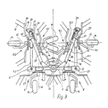
- this respective fork part 27 has such a length that an inward pivoting movement of the outer side supports 4.2, 5.2 can be made through with the associated rotary rakes 6.1, 9.2 so far that the lower arms 10 or rake tines in the transport protection position 11 end near the center beam 1 (Fig. 3). With the selected size ratios in the illustrated embodiment, this results in a ratio l1 to l2 of approximately 0.4, the vertical axes 12 of the outer rotary rakes 6.1, 9.2 in the transport protection position cutting the horizontal at an angle of approximately 20 °.
- the machine In this transport protection position, the machine has a transport height which corresponds approximately to that of a device with a total of four rotary rakes of known design, although the outer side beams located inward above the center beam, together with their parts, have a favorable influence on the overall center of gravity of the machine and in this space without There is a safe risk of injury for operators.
- the wheels 14 of the outer side supports 4.2, 5.2 are offset from the vertical axes 12 of the outer rotary rakes 6.1, 9.2 laterally to the respective outside of the machine in such a way that they are able to lie one above the other in the transport protection position (FIG. 3).
- the wheels 14 are fastened by means of appropriately cranked holders.
- the wheels 14 of the center support 1 of the machine are also offset with respect to the vertical axes 12 of the rotary rakes 7 and 8, which results in improved tilting stability and thus stability in the transport protection position.
- a pressure medium drive 17, 18 is provided for both side support units, which is connected at one end to the central support 1 via the flange part 22.1 and at the other end articulates in the central region of the actuating lever 36.
- One end of the actuating lever 36 is guided in a longitudinally displaceable and articulated manner on a guide link part 37 which is held on the outer side support 4.2 or 5.2 and whose guide link has end stops 38 and 39.
- the actuating lever 36 With its opposite end, the actuating lever 36 is articulated on a connection connecting part 40 of the fork 27, the position of the joints 41, 42 and that of the end stops 38, 39 being selected such that when the pressure medium drives 17, 18 are retracted, the actuating lever is in contact after inner end stop 39, both side supports 4.1, 4.2 are transferred to the transport position, so that the machine parts can be transferred to the transport position in a structurally simple manner, even in this exemplary embodiment with only one pressure medium drive per side support unit.
- any other suitable drive or drive transmission device can also be provided, e.g. B. in the form of an independent pressure medium drive, the application of which can be coordinated with the application of pressure medium drives 17.
- the pivot axes 2, 3, 23 and 24 and the joint 32 are aligned parallel to the direction of travel in the exemplary embodiments described, but certain deviations can be made here which do not exceed a certain degree should.
- the side supports or the rotary rakes are provided in such a way that the vertical axes 12 of the rotary rakes of the outer side supports incline forward in the operating position to the horizontal, which can be achieved that when lifting the machine in the Do not move the rotary rake in the transport position too close to the tractor.
Applications Claiming Priority (8)
| Application Number | Priority Date | Filing Date | Title |
|---|---|---|---|
| DE3713474 | 1987-04-22 | ||
| DE19873713474 DE3713474A1 (de) | 1987-04-22 | 1987-04-22 | Heuwerbungsmaschine |
| DE8716698U DE8716698U1 (fr) | 1987-04-22 | 1987-12-18 | |
| DE8716698U | 1987-12-18 | ||
| DE3801804 | 1988-01-22 | ||
| DE19883801804 DE3801804A1 (de) | 1987-04-22 | 1988-01-22 | Heuwerbungsmaschine |
| DE19883801803 DE3801803A1 (de) | 1987-04-22 | 1988-01-22 | Heuwerbungsmaschine |
| DE3801803 | 1988-01-22 |
Related Parent Applications (1)
| Application Number | Title | Priority Date | Filing Date |
|---|---|---|---|
| EP88106297.0 Division | 1988-04-20 |
Publications (2)
| Publication Number | Publication Date |
|---|---|
| EP0429433A2 true EP0429433A2 (fr) | 1991-05-29 |
| EP0429433A3 EP0429433A3 (en) | 1994-05-18 |
Family
ID=27433908
Family Applications (2)
| Application Number | Title | Priority Date | Filing Date |
|---|---|---|---|
| EP19910101481 Withdrawn EP0429433A3 (en) | 1987-04-22 | 1988-04-20 | Hay-making machine |
| EP88106297A Expired - Lifetime EP0289864B1 (fr) | 1987-04-22 | 1988-04-20 | Machine de fenaison |
Family Applications After (1)
| Application Number | Title | Priority Date | Filing Date |
|---|---|---|---|
| EP88106297A Expired - Lifetime EP0289864B1 (fr) | 1987-04-22 | 1988-04-20 | Machine de fenaison |
Country Status (2)
| Country | Link |
|---|---|
| EP (2) | EP0429433A3 (fr) |
| DE (1) | DE3874950D1 (fr) |
Cited By (1)
| Publication number | Priority date | Publication date | Assignee | Title |
|---|---|---|---|---|
| EP0784920A1 (fr) * | 1996-01-22 | 1997-07-23 | Maasland N.V. | Machine agricole |
Families Citing this family (8)
| Publication number | Priority date | Publication date | Assignee | Title |
|---|---|---|---|---|
| DE3903764A1 (de) * | 1989-02-09 | 1990-08-16 | Claas Saulgau Gmbh | Kreiselheumaschinen |
| DE9010179U1 (fr) * | 1990-07-04 | 1990-09-20 | H. Niemeyer Soehne Gmbh & Co Kg, 4446 Hoerstel, De | |
| FR2664127B1 (fr) * | 1990-07-05 | 1994-05-27 | Kuhn Sa | Machine agricole, notamment une andaineuse de vegetaux, a largeur de travail reglable. |
| DE4114580C2 (de) * | 1991-05-04 | 1993-11-18 | Fella Werke Gmbh | Landwirtschaftliche Maschine mit veränderbarer Arbeitsbreite |
| DE19541355A1 (de) * | 1995-11-07 | 1997-05-15 | Claas Saulgau Gmbh | Verfahren und Vorrichtung zum Schwenken von Zinkenkreiseln für Vielkreiselheuwender |
| DE19835125A1 (de) * | 1998-08-04 | 2000-02-10 | Amazonen Werke Dreyer H | Landwirtschaftliche Arbeitsmaschine |
| FR2789848B1 (fr) * | 1999-02-19 | 2001-05-25 | Kuhn Sa | Machine de fenaison comportant un chassis compose de plusieurs troncons articules entre eux |
| DE19920755A1 (de) * | 1999-05-05 | 2000-11-09 | Claas Saulgau Gmbh | Heuwerbungsmaschine |
Citations (8)
| Publication number | Priority date | Publication date | Assignee | Title |
|---|---|---|---|---|
| US3844358A (en) * | 1973-02-16 | 1974-10-29 | J Dyck | Folding system for multi-sectional implement |
| US4178998A (en) * | 1978-04-17 | 1979-12-18 | Allis-Chalmers Corporation | Folding mechanism for a multiple section agricultural implement |
| US4206816A (en) * | 1976-08-24 | 1980-06-10 | Richardson Manufacturing Company, Inc. | Folding flexible undercutter plow |
| DE3031837A1 (de) * | 1979-08-24 | 1981-03-12 | C. van der Lely N.V., 3155 Maasland | Heuwerbungsmaschine. |
| EP0136535A1 (fr) * | 1983-09-15 | 1985-04-10 | Deere & Company | Outillage utilisable dans l'agriculture |
| US4615397A (en) * | 1985-10-30 | 1986-10-07 | Deutz-Allis Corporation | Agricultural implement with double wing folding mechanism using toggle linkage and hydraulic actuator |
| EP0203023A1 (fr) * | 1985-05-21 | 1986-11-26 | Kuhn S.A. | Perfectionnement aux machines de fenaison munies de plusieurs roues râteleuses |
| DE8625784U1 (fr) * | 1986-09-26 | 1987-03-05 | Kloeckner-Humboldt-Deutz Ag Zweigniederlassung Fahr, 7702 Gottmadingen, De |
Family Cites Families (1)
| Publication number | Priority date | Publication date | Assignee | Title |
|---|---|---|---|---|
| FR1553252A (fr) * | 1968-01-19 | 1969-01-10 |
-
1988
- 1988-04-20 DE DE8888106297T patent/DE3874950D1/de not_active Expired - Fee Related
- 1988-04-20 EP EP19910101481 patent/EP0429433A3/de not_active Withdrawn
- 1988-04-20 EP EP88106297A patent/EP0289864B1/fr not_active Expired - Lifetime
Patent Citations (8)
| Publication number | Priority date | Publication date | Assignee | Title |
|---|---|---|---|---|
| US3844358A (en) * | 1973-02-16 | 1974-10-29 | J Dyck | Folding system for multi-sectional implement |
| US4206816A (en) * | 1976-08-24 | 1980-06-10 | Richardson Manufacturing Company, Inc. | Folding flexible undercutter plow |
| US4178998A (en) * | 1978-04-17 | 1979-12-18 | Allis-Chalmers Corporation | Folding mechanism for a multiple section agricultural implement |
| DE3031837A1 (de) * | 1979-08-24 | 1981-03-12 | C. van der Lely N.V., 3155 Maasland | Heuwerbungsmaschine. |
| EP0136535A1 (fr) * | 1983-09-15 | 1985-04-10 | Deere & Company | Outillage utilisable dans l'agriculture |
| EP0203023A1 (fr) * | 1985-05-21 | 1986-11-26 | Kuhn S.A. | Perfectionnement aux machines de fenaison munies de plusieurs roues râteleuses |
| US4615397A (en) * | 1985-10-30 | 1986-10-07 | Deutz-Allis Corporation | Agricultural implement with double wing folding mechanism using toggle linkage and hydraulic actuator |
| DE8625784U1 (fr) * | 1986-09-26 | 1987-03-05 | Kloeckner-Humboldt-Deutz Ag Zweigniederlassung Fahr, 7702 Gottmadingen, De |
Cited By (2)
| Publication number | Priority date | Publication date | Assignee | Title |
|---|---|---|---|---|
| EP0784920A1 (fr) * | 1996-01-22 | 1997-07-23 | Maasland N.V. | Machine agricole |
| NL1002141C2 (nl) * | 1996-01-22 | 1997-07-25 | Maasland Nv | Landbouwmachine. |
Also Published As
| Publication number | Publication date |
|---|---|
| DE3874950D1 (de) | 1992-11-05 |
| EP0289864A1 (fr) | 1988-11-09 |
| EP0289864B1 (fr) | 1992-09-30 |
| EP0429433A3 (en) | 1994-05-18 |
Similar Documents
| Publication | Publication Date | Title |
|---|---|---|
| DE2426209B2 (de) | Landmaschine | |
| DE3031837A1 (de) | Heuwerbungsmaschine. | |
| DE1782461A1 (de) | Maehdrescher | |
| EP1095555B1 (fr) | Machine de fenaison | |
| DE3632767C2 (fr) | ||
| EP0429433A2 (fr) | Machine de fenaison | |
| EP0600304B1 (fr) | Machine pour la fenaison | |
| DE10327915B4 (de) | Heuwerbungsmaschine | |
| DE2141086C3 (de) | Anbaubock zum Anschließen einer Landmaschine an einen Schlepper | |
| DE2137005C3 (de) | Heuwerbungsmaschine Ausscheidung in: 21 67 001 21 67 002 Schüttler, Jacques-Roby, Dr, Andeer bei Clugin (Schweiz) | |
| EP0288416B1 (fr) | Machine de fenaison | |
| DE2127701B1 (de) | Heuwerbungsmaschine | |
| EP0534127A1 (fr) | Machine de fenaison | |
| AT393344B (de) | Kreiselheuwerbungsmaschine | |
| DE2844235A1 (de) | Heuwerbungsmaschine | |
| DE2004349A1 (de) | Heuwerbungsmaschine | |
| DE2529928C2 (de) | Anbauvorrichtung für eine landwirtschaftliche Maschine | |
| DE1582167C2 (de) | Kreiselheuwerbungsmaschine | |
| DE3107696A1 (de) | Bodenbearbeitungsmaschine | |
| DE4111267A1 (de) | Heuwerbungsmaschine | |
| DE1582292B2 (de) | Mähmaschine | |
| AT392192B (de) | Rotationsmaehwerk | |
| EP0651938A1 (fr) | Machine de fenaison | |
| DE3038584C2 (fr) | ||
| DE1582293C3 (de) | Mähmaschine C. van der LeIy N.V, Maasland (Niederlande) |
Legal Events
| Date | Code | Title | Description |
|---|---|---|---|
| PUAI | Public reference made under article 153(3) epc to a published international application that has entered the european phase |
Free format text: ORIGINAL CODE: 0009012 |
|
| AC | Divisional application: reference to earlier application |
Ref document number: 289864 Country of ref document: EP |
|
| AK | Designated contracting states |
Kind code of ref document: A2 Designated state(s): AT BE CH DE FR GB LI NL |
|
| PUAL | Search report despatched |
Free format text: ORIGINAL CODE: 0009013 |
|
| AK | Designated contracting states |
Kind code of ref document: A3 Designated state(s): AT BE CH DE FR GB LI NL |
|
| 17P | Request for examination filed |
Effective date: 19940614 |
|
| 17Q | First examination report despatched |
Effective date: 19960209 |
|
| RAP1 | Party data changed (applicant data changed or rights of an application transferred) |
Owner name: NIEMEYER LANDMASCHINEN GMBH |
|
| GRAG | Despatch of communication of intention to grant |
Free format text: ORIGINAL CODE: EPIDOS AGRA |
|
| GRAG | Despatch of communication of intention to grant |
Free format text: ORIGINAL CODE: EPIDOS AGRA |
|
| GRAH | Despatch of communication of intention to grant a patent |
Free format text: ORIGINAL CODE: EPIDOS IGRA |
|
| STAA | Information on the status of an ep patent application or granted ep patent |
Free format text: STATUS: THE APPLICATION IS DEEMED TO BE WITHDRAWN |
|
| 18D | Application deemed to be withdrawn |
Effective date: 20000303 |