EP0429433A2 - Hay-making machine - Google Patents
Hay-making machine Download PDFInfo
- Publication number
- EP0429433A2 EP0429433A2 EP91101481A EP91101481A EP0429433A2 EP 0429433 A2 EP0429433 A2 EP 0429433A2 EP 91101481 A EP91101481 A EP 91101481A EP 91101481 A EP91101481 A EP 91101481A EP 0429433 A2 EP0429433 A2 EP 0429433A2
- Authority
- EP
- European Patent Office
- Prior art keywords
- rake
- axes
- support
- rotary
- transport
- Prior art date
- Legal status (The legal status is an assumption and is not a legal conclusion. Google has not performed a legal analysis and makes no representation as to the accuracy of the status listed.)
- Withdrawn
Links
Images

Classifications
-
- A—HUMAN NECESSITIES
- A01—AGRICULTURE; FORESTRY; ANIMAL HUSBANDRY; HUNTING; TRAPPING; FISHING
- A01D—HARVESTING; MOWING
- A01D78/00—Haymakers with tines moving with respect to the machine
- A01D78/08—Haymakers with tines moving with respect to the machine with tine-carrying rotary heads or wheels
- A01D78/10—Haymakers with tines moving with respect to the machine with tine-carrying rotary heads or wheels the tines rotating about a substantially vertical axis
- A01D78/1007—Arrangements to facilitate transportation specially adapted therefor
- A01D78/1014—Folding frames
Definitions
- the invention relates to a haymaking machine in an embodiment according to the preamble of claim 1.
- the side members consist of an inner and outer part, the outer part about the longitudinal central axis of the side member common to the two parts is to be pivoted by 180 ° relative to the inner part. This enables the outer rotary rakes to be transferred to a transport protection position in which the rake tines extend with their ends towards the center of the device when the side carriers are folded up.
- the pivoting of the rotary rake around the longitudinal central axis of the side supports or a slightly inclined axis to the transport protection position can be independent of the pivoting up of the side supports, i. H. before or after swinging up, be done by hand.
- an operator must dismount from the driver's seat, release the respective locks, pivot the outer parts of the side supports, restore the lock and finally climb on the tractor again before starting a transport journey.
- This is time-consuming, cumbersome, involves a certain amount of effort as well as a snappy danger to the operator from the tine tips, since the operator is in the range of movement of the rake tines when the rotary rake is pivoted into the transport protection position.
- the pivoting of the rake tines in the transport protection position can also be done during the swiveling up the side supports are carried out by a gear that transmits a pivoting movement derived from the swiveling-up movement of the side supports to the outer part of the side support carrying the rotary rake.
- a gear that transmits a pivoting movement derived from the swiveling-up movement of the side supports to the outer part of the side support carrying the rotary rake.
- Such a transmission comprising a rack and toothed segments as well as cranks and transmission levers is structurally extremely complex and also very sensitive, so that regular maintenance is required for reliable functioning.
- the inwardly directed rake tines, with their ends causing injury lie at the height of people, so that the risk of injury compared to an outwardly directed position of the rake tines is reduced, but not eliminated.
- the central side support is to be folded up from the working position into an approximately upright transport position.
- the outer side support which is articulated on the middle side supports near the vertical axis of its rotary rake, is to be transferred together with the outer rotary rake in a transport protection position pivoted towards the center of the device, in which the longitudinal central axes of the outer side supports are oriented obliquely upwards and the side supports are to a certain extent assume a position corresponding to the triangular sides.
- the resulting transport height of the machine is considerable, has an unfavorable influence on the center of gravity of the device towards the tractor, thus has reduced tilting stability and in many cases makes it impossible to drive through gates and the like during the transport journey.
- the rotary rakes of the outer side supports are generally to be rotated manually in the course of the transfer of the side supports to this transport position in such a way that Rake tines of the two rotary rakes can cross each other, causing time delays lead and make adjustment work in the area of rake tines with not inconsiderable risk of injury necessary.
- the invention has for its object to provide structurally simple means of a haymaking machine of the type mentioned, in which in an embodiment with two side supports on each side of the central support, each outer side support in a transport position with known devices a reduced transport height and an improved center of gravity to Tractors are to be transferred.
- the haymaking machine according to the invention is designed with structurally simple means as a six-rotor rake, in which an outer or the respective outer rotary rake inwards by more than 90 °, i. H. to the center of the device, swivel or let it fold so that the rake tines are to be brought into a transport space that is laterally limited at least in some areas by side support parts and extends above the center support when the swivel movement is more than 90 °.
- a transport height of the machine in the transport position can thus be achieved, which is significantly lower than known machines of this type. This goes hand in hand with a much improved center of gravity of the machine.
- the illustrated haymaking machine consists of a tubular crossmember that can be attached to an agricultural tractor (not shown), which comprises a central girder 1 and side girders 4.1, 4.2, 5.1, 5.2 articulated to it about an axis 2, 3 parallel to the direction of travel.
- the haymaking machine is provided in the exemplary embodiment according to FIGS. 1 to 3 with a number of rotary rakes 6.1, 6.2, 7, 8, 9.1, 9.2, which have rake tines 11 on the outer ends of arms arranged in a star shape, which in the operating position of the parts for Are directed towards the floor.
- All rotary rakes are rotatably mounted on the crossmember about vertical axes 12, two rotary rakes 7, 8 being assigned to the central support 1 and one rotary rake 6.1, 6.2 or 9.1, 9.2 each to the side supports 4.1, 4.2 or 5.1, 5.2.
- the gyro rakes are by means of a Drive shaft mounted in the crossmember can be driven, which receives its rotary movement from a central gear 13 which can be connected to the PTO of the tractor. Details in the design of the drive shaft, insofar as they are important, will be discussed further below.
- the haymaking machine also includes wheels 14 which support the machine on the ground during operation and are each arranged under a rotary rake.
- the side supports 4.1, 5.1, 4.2, 5.2 of the machines shown with six rotary rakes are together with the rotary rakes 6.1, 6.2, 9.1, 9.2 assigned to them at the outer end about the direction-parallel pivot axes 2 and 3 in the direction of the arrows 15, 16 shown in their im Operation can be pivoted up into a substantially horizontal position in a transport position.
- pressure medium drives 17, 18 are provided, the cylinders 19 of which engage in articulated fashion on a flange part 22.1 which is supported in a stationary manner above the central support 1 and whose piston rods 21 are articulated with an adjusting lever 36 on the Side carriers 4.2 and 5.2 are connected.
- the outer side supports 4.2, 5.2 together with the associated outer rotary rakes 6.1, 9.2 around the additional axes 23, 24 parallel to the direction of travel are more than 90 inward compared to the central side supports 4.1, 5.1 oriented vertically in the transport position ° to pivot, according to which these parts are located in a transport space which extends above the central support 1 and which laterally in the transport position through the central side supports 4.1, 5.1 and at the outer ends of fork parts 27 for articulated mounting of the outer side supports 4.2, 5.2 is limited.
- the side supports 4.1, 5.1 have a fork 27 at their outer end, the legs of which support the outer side supports 4.2, 5.2 with the rotary rakes 6.1 and 9.2, respectively, about the additional axis 23, 24.
- a bearing and gear housing 28 forms, as it were, the outermost end of this associated side carrier 4.2, 5.2 or an axial extension thereof and, like the side carriers 4.2, 5.2, encloses the associated part of the drive shaft 29, both in the area of the axes 2, 3 , as well as in the area of the additional axes 23, 24 is provided with a universal joint 30 and 31, respectively.
- the joint axes of these universal joints 30, 31 lie with the axis 2, 3 or the additional axis 23, 24 in a common plane.
- the position distance l 1 of the intersection of an additional axis 23, 24 with the corresponding longitudinal central axis 25, 26 of the side supports has, in accordance with FIG. 1 in relation to the position distance l 2 of the vertical axes 12 of the rotary rakes 6.1 to 6.2 or 9.1, 9.2 of the respective side supports, again such a measure that the ratio of l1 to l2 is greater than or equal to 0.3.
- the lateral positional distance l 1 of the respective additional axles 23, 24 can be varied in a structurally simple manner by the dimensions of the fork part 27 in which the outer side supports 4.2, 5.2 are articulated. In the illustrated embodiment according to FIG.
- this respective fork part 27 has such a length that an inward pivoting movement of the outer side supports 4.2, 5.2 can be made through with the associated rotary rakes 6.1, 9.2 so far that the lower arms 10 or rake tines in the transport protection position 11 end near the center beam 1 (Fig. 3). With the selected size ratios in the illustrated embodiment, this results in a ratio l1 to l2 of approximately 0.4, the vertical axes 12 of the outer rotary rakes 6.1, 9.2 in the transport protection position cutting the horizontal at an angle of approximately 20 °.
- the machine In this transport protection position, the machine has a transport height which corresponds approximately to that of a device with a total of four rotary rakes of known design, although the outer side beams located inward above the center beam, together with their parts, have a favorable influence on the overall center of gravity of the machine and in this space without There is a safe risk of injury for operators.
- the wheels 14 of the outer side supports 4.2, 5.2 are offset from the vertical axes 12 of the outer rotary rakes 6.1, 9.2 laterally to the respective outside of the machine in such a way that they are able to lie one above the other in the transport protection position (FIG. 3).
- the wheels 14 are fastened by means of appropriately cranked holders.
- the wheels 14 of the center support 1 of the machine are also offset with respect to the vertical axes 12 of the rotary rakes 7 and 8, which results in improved tilting stability and thus stability in the transport protection position.
- a pressure medium drive 17, 18 is provided for both side support units, which is connected at one end to the central support 1 via the flange part 22.1 and at the other end articulates in the central region of the actuating lever 36.
- One end of the actuating lever 36 is guided in a longitudinally displaceable and articulated manner on a guide link part 37 which is held on the outer side support 4.2 or 5.2 and whose guide link has end stops 38 and 39.
- the actuating lever 36 With its opposite end, the actuating lever 36 is articulated on a connection connecting part 40 of the fork 27, the position of the joints 41, 42 and that of the end stops 38, 39 being selected such that when the pressure medium drives 17, 18 are retracted, the actuating lever is in contact after inner end stop 39, both side supports 4.1, 4.2 are transferred to the transport position, so that the machine parts can be transferred to the transport position in a structurally simple manner, even in this exemplary embodiment with only one pressure medium drive per side support unit.
- any other suitable drive or drive transmission device can also be provided, e.g. B. in the form of an independent pressure medium drive, the application of which can be coordinated with the application of pressure medium drives 17.
- the pivot axes 2, 3, 23 and 24 and the joint 32 are aligned parallel to the direction of travel in the exemplary embodiments described, but certain deviations can be made here which do not exceed a certain degree should.
- the side supports or the rotary rakes are provided in such a way that the vertical axes 12 of the rotary rakes of the outer side supports incline forward in the operating position to the horizontal, which can be achieved that when lifting the machine in the Do not move the rotary rake in the transport position too close to the tractor.
Abstract
Die Erfindung bezieht sich auf eine Heuwerbungsmaschine mit einem an einen landwirtschaftlichen Schlepper anhäng- oder an dessen Dreipunkthydraulik anbaubaren Querträger, der ein Mittelträger 1 und zumindest jeweils einen beidseits des Mittelträgers 1 vorgesehenen, um eine etwa fahrtrichtungsparallele Achse 2,3 gelenkig verbundenen Seitenträger 4.1,4.2,5.1,5.2 umfaßt, mit einer Anzahl von in Betriebsstellung zum Boden hin gerichtete Rechzinken 11 aufweisenden Kreiselrechen 6.1,6.2,7,8,9.1,9.2, die am Querträger um Hochachsen 12 drehbar gelagert und mittels einer im Querträger gelagerten Antriebswelle 29 antreibbar sind, sowie mit Laufrädern 14, welche die Maschine während des Betriebs auf dem Boden abstützen und jeweils unter einem Kreiselrechen 6.1,6.2,7,8,9.1,9.2 geordnet sind. Dabei ist ein Druckmittelantrieb 17,18 zum Hochschwenken der Seitenträger 4.1,4.2,5.1,5.2 und zum Festlegen einer Transportstellung vorgesehen, wobei jedem Seitenträger 4.1,4.2,5.1,5.2 ein Kreiselrechen zugeordnet ist, der sich am Außenendbereich seines Seitenträgers abstützt. Zudem sind die äußeren Kreiselrechen n 6.1,9.2 um eine Zusatzachse in eine Transportschutzstellung überführbar. Die Zusatzachsen 23,24 sind fahrtrichtungsparallel ausgerichtet, wobei zumindest einer der einem äußeren Seitenträger 4.2,5.2 zugeordneten Kreiselrechen 6.1,9.2 mitsamt seinem zugehörigen Seitenträger um mehr als 90° in eine Transportschutzstellung klappbar ist, in der sich in einem oberhalb des Mittelträgers 1 gelegenen sowie zumindest bereichsweise seitlich durch einen Transportschutzstellung überführten mittleren Seitenträger 4.1,5.1 begrenbaren Raum erstreckt. <IMAGE>The invention relates to a haymaking machine with a crossmember that can be attached to an agricultural tractor or can be attached to its three-point hydraulic system, which has a central girder 1 and at least one side girder 4.1.4.2 provided on both sides of the central girder 1 about an axis parallel to the direction of travel 2.3 , 5.1,5.2 comprises, with a number of rake tines 11 directed towards the ground in the operating position, having 6.16.2.7.8.9.1.9.2 rotatably mounted on the cross member about vertical axes 12 and being drivable by means of a drive shaft 29 mounted in the cross member , as well as with wheels 14 which support the machine on the ground during operation and are each arranged under a rotary rake 6.1.6.2.7.8.9.1.9.2. In this case, a pressure medium drive 17, 18 is provided for swiveling the side supports 4.1, 4.2.5, 1.5.2 and for defining a transport position, with each side support 4.1, 4.2, 1.5, 5, 2 being assigned a rotary rake which is supported on the outer end region of its side support. In addition, the outer rotary rakes n 6.1.9.2 can be moved into an transport protection position around an additional axis. The additional axes 23, 24 are aligned parallel to the direction of travel, with at least one of the rotary rakes 6.1, 9.2 assigned to an outer side support 4.2, 5.2.2, together with its associated side support, being foldable by more than 90 ° into a transport protection position, in which a position located above the central support 1 and At least in some areas, space that can be limited laterally by a central side carrier 4.1, 5.1. <IMAGE>
Description
Die Erfindung bezieht sich auf eine Heuwerbungsmaschine in einer Ausbildung gemäß dem Oberbegriff des Anspruchs 1.The invention relates to a haymaking machine in an embodiment according to the preamble of
Bei einer bekannten Maschine mit einem Querträger, der beidseits des Mittelträgers je einen Seitenträger mit zugeordnetem Kreiselrechen umfaßt (EP-A 02 03 023), bestehen die Seitenträger aus einem Innen- und Außenteil, wobei der Außenteil um die den beiden Teilen gemeinsame Längsmittelachse des Seitenträgers relativ zum Innenteil um 180° zu verschwenken ist. Dies ermöglicht, die äußeren Kreiselrechen in eine Transportschutzstellung zu überführen, in der sich bei hochgeklappten Seitenträgern die Rechzinken mit ihren Enden zur Gerätemitte hin erstrecken.In a known machine with a cross member, which comprises a side member with an associated rotary rake on each side of the middle member (EP-A 02 03 023), the side members consist of an inner and outer part, the outer part about the longitudinal central axis of the side member common to the two parts is to be pivoted by 180 ° relative to the inner part. This enables the outer rotary rakes to be transferred to a transport protection position in which the rake tines extend with their ends towards the center of the device when the side carriers are folded up.
Das Verschwenken der Kreiselrechen um die Längsmittelachse der Seitenträger oder eine dazu leicht geneigte Achse in die Transportschutzstellung kann unabhängig vom Hochschwenken der Seitenträger, d. h. vor oder nach dem Hochschwenken, von Hand vorgenommen werden. In diesem Fall muß eine Bedienperson vom Fahrersitz absteigen, die jeweiligen Verriegelungen lösen, die Verschwenkung der Außenteile der Seitenträger vornehmen, die Verriegelung wieder herstellen und schließlich den Schlepper wieder besteigen, bevor eine Transportfahrt angetreten werden kann. Dies ist zeitraubend, umständlich, mit einigem Kraftaufwand sowie auch mit einer gerissen Gefährdung der Bedienperson durch die Zinkenspitzen verbunden, da sich die Bedienperson im Bewegungsbereich der Rechzinken beim Schwenken der Kreiselrechen in die Transportschutzstellung befindet.The pivoting of the rotary rake around the longitudinal central axis of the side supports or a slightly inclined axis to the transport protection position can be independent of the pivoting up of the side supports, i. H. before or after swinging up, be done by hand. In this case, an operator must dismount from the driver's seat, release the respective locks, pivot the outer parts of the side supports, restore the lock and finally climb on the tractor again before starting a transport journey. This is time-consuming, cumbersome, involves a certain amount of effort as well as a snappy danger to the operator from the tine tips, since the operator is in the range of movement of the rake tines when the rotary rake is pivoted into the transport protection position.
Statt dessen kann das Verschwenken der Rechzinken in die Transportschutzstellung auch während des Hochschwenkens der Seitenträger durch ein Getriebe erfolgen, das eine von der Hochschwenkbewegung der Seitenträger abgeleitete Schwenkbewegung auf den den Kreiselrechen tragenden Außenteil des Seitenträgers überträgt. Ein solches, eine Zahnstange und Zahnsegmente sowie Kurbeln und Übertragungshebel umfassendes Getriebe ist baulich außerordentlich aufwendig und zudem sehr empfindlich, so daß es für ein zuverlässiges Funktionieren der regelmäßigen Wartung bedarf. Insbesondere aber liegen die nach innen gerichteten Rechzinken mit ihren Verletzungsgefahren hervorrufenden Enden in Körperhöhe von Personen, so daß Gefahren von Verletzungen gegenüber einer nach außen gerichteten Lage der Rechzinken zwar gemindert, nicht jedoch beseitigt sind.Instead, the pivoting of the rake tines in the transport protection position can also be done during the swiveling up the side supports are carried out by a gear that transmits a pivoting movement derived from the swiveling-up movement of the side supports to the outer part of the side support carrying the rotary rake. Such a transmission comprising a rack and toothed segments as well as cranks and transmission levers is structurally extremely complex and also very sensitive, so that regular maintenance is required for reliable functioning. In particular, however, the inwardly directed rake tines, with their ends causing injury, lie at the height of people, so that the risk of injury compared to an outwardly directed position of the rake tines is reduced, but not eliminated.
Bei einer anderen bekannten Maschine mit einem Querträger, der einen Mittelträger sowie beidseits des Mittelträgers je einen mittleren und äußeren Seitenträger umfaßt (DE-GM 86 25 78d.6), ist der mittlere Seitenträger aus der Arbeitsstellung hochzuklappen in eine annähernd aufrechte Transportstellung. Der an den mittleren Seitenträgern nahe der Hochachse seines Kreiselrechens gelenkig angreifende äußere Seitenträger ist mitsamt dem äußeren Kreiselrechen in einer zur Gerätemitte hin um die Zusatzachse verschwenkte Transportschutzstellung zu überführen, in der die Längsmittelachsen der äußeren Seitenträger schräg nach oben verlaufend ausgerichtet sind und die Seitenträger zueinander gewissermaßen eine Dreieckseitenschenkeln entsprechende Lage einnehmen. Die dadurch bedingte Transporthöhe der Maschine ist erheblich, beeinflußt die Schwerpunktlage des Gerätes zum Schlepper hin ungünstig, hat damit eine verminderte Kippstabilität und macht ein Durchfahren von Toren und dgl. während der Transportfahrt in vielen Fällen unmöglich. Um eine Dreieckseitenschenkeln entsprechende Lage einnehmen zu können, d. h., daß die Endbereiche der beiden äußeren Seitenträger einander in der Transportstellung annähernd berühren, sind die Kreiselrechen der äußeren Seitenträger in der Regel manuell im Verlaufe der Überführung der Seitenträger in diese Transportstellung derart zu verdrehen, daß sich Rechzinken der beiden Kreiselrechen einander kreuzen können, was zu zeitlichen Verzögerungen führen und Justierarbeiten im Bereich von Rechzinken mit nicht unerheblichem Verletzungsrisiko erforderlich machen kann.In another known machine with a cross member, which comprises a central support and a central and external side supports on each side of the central support (DE-GM 86 25 78d.6), the central side support is to be folded up from the working position into an approximately upright transport position. The outer side support, which is articulated on the middle side supports near the vertical axis of its rotary rake, is to be transferred together with the outer rotary rake in a transport protection position pivoted towards the center of the device, in which the longitudinal central axes of the outer side supports are oriented obliquely upwards and the side supports are to a certain extent assume a position corresponding to the triangular sides. The resulting transport height of the machine is considerable, has an unfavorable influence on the center of gravity of the device towards the tractor, thus has reduced tilting stability and in many cases makes it impossible to drive through gates and the like during the transport journey. In order to be able to assume a position corresponding to triangular side legs, that is to say that the end regions of the two outer side supports approximately touch each other in the transport position, the rotary rakes of the outer side supports are generally to be rotated manually in the course of the transfer of the side supports to this transport position in such a way that Rake tines of the two rotary rakes can cross each other, causing time delays lead and make adjustment work in the area of rake tines with not inconsiderable risk of injury necessary.
Der Erfindung liegt die Aufgabe zugrunde, mit baulich einfachen Mitteln eine Heuwerbungsmaschine der eingangs genannten Art zu schaffen, bei der in einer Ausbildung mit je zwei Seitenträgern beidseits des Mittelträgers jeweils äußeren Seitenträger in eine Transportstellung mit gegenüber bekannten Geräten einer verringerten Transporthöhe sowie einer verbesserten Schwerpunktlage zum Schlepper hin zu überführen sind.The invention has for its object to provide structurally simple means of a haymaking machine of the type mentioned, in which in an embodiment with two side supports on each side of the central support, each outer side support in a transport position with known devices a reduced transport height and an improved center of gravity to Tractors are to be transferred.
Die Erfindung löst diese Aufgabe ausgehend von einer Heuwerbungsmaschine gemäß dem Oberbegriff des Anspruchs 1 mit den Merkmalen des kennzeichnenden Teils dieses Anspruchs. Hinsichtlich wesentlicher weiterer Ausgestaltungen der Erfindung wird auf die Ansprüche 2 bis 7 verwiesen.The invention solves this problem on the basis of a haymaking machine according to the preamble of
Die Heuwerbungsmaschine nach der Erfindung ist mit baulich einfachen Mitteln als Sechskreiselrechenmaschine ausgebildet, bei der sich ein äußerer oder die jeweils äußeren Kreiselrechen um mehr als 90° Grad einwärts, d. h. zur Gerätemitte hin, verschwenken bzw. klappen lassen, so daß die Rechzinken bei einer Schwenkbewegung von mehr als 90° in einen zumindest bereichsweise durch Seitenträgerteile seitlich begrenzten Transportraum zu bringen sind, der sich oberhalb des Mittelträgers erstreckt. Damit läßt sich eine Transporthöhe der Maschine in der Transportstellung verwirklichen, die gegenüber bekannten Maschinen dieser Art deutlich geringer ist. Damit geht auch eine weit verbesserte Schwerpunktlage der Maschine einher.The haymaking machine according to the invention is designed with structurally simple means as a six-rotor rake, in which an outer or the respective outer rotary rake inwards by more than 90 °, i. H. to the center of the device, swivel or let it fold so that the rake tines are to be brought into a transport space that is laterally limited at least in some areas by side support parts and extends above the center support when the swivel movement is more than 90 °. A transport height of the machine in the transport position can thus be achieved, which is significantly lower than known machines of this type. This goes hand in hand with a much improved center of gravity of the machine.
Eine äußerst kompakte und hinsichtlich der Gesamtschwerpunktlage günstige Maschinenausführung ergibt sich z. B. bei dieser Maschinenausbildung, bei der die äußeren Seitenträger mit fest an diesen angeordneten äußeren Kreiselrechen um die Zusatzachsen einwärts so einzuklappen bzw. einzuschwenken sind, daß die äußeren Enden von Rechzinken in der Transportschutzstellung in etwa am Mittelträger anliegen. Hierbei entspricht die Transporthöhe einer Maschinen-ausführung mit insgesamt sechs Kreiselrechen im wesentlichen der Transporthöhe einer Maschine mit vier Kreiselrechen und jeweils nur einem in die Vertikale verschwenkbaren Seitenträger.An extremely compact machine design that is favorable in terms of the overall center of gravity results, for. B. in this machine design, in which the outer side supports with fixedly arranged on these external rotary rakes to fold in or in so that the outer ends of rake teeth in the transport protection position abut approximately on the central support. The transport height of a machine version with a total of six rotary rakes essentially corresponds to the transport height of a machine with four rotary rakes and only one side beam that can be pivoted vertically.
Weitere Einzelheiten und Vorteile ergeben sich aus der nachfolgenden Beschreibung und der Zeichnung, in der ein Ausführungsbeispiel des Gegenstands der Erfindung schematisch näher veranschaulicht ist. In der Zeichnung zeigen:
- Fig.1
- eine schematische Rückansicht einer Heuwerbungsmaschine nach der Erfindung mit sechs Kreiselrechen in Betriebsstellung der Teile;
- Fig. 2
- eine Draufsicht auf das Ausführungsbeispiel nach Fig. 1, und
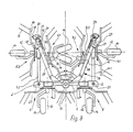
- Fig. 3
- eine Darstellung des Ausführungsbeispiels nach Fig. 1 mit in Transportstellung überführten Teilen.
- Fig. 1
- is a schematic rear view of a haymaking machine according to the invention with six rotary rakes in the operating position of the parts;
- Fig. 2
- a plan view of the embodiment of FIG. 1, and
- Fig. 3
- a representation of the embodiment of FIG. 1 with parts transferred into the transport position.
Bei dem in der Zeichnung veranschaulichten Ausführungsbeispiel sind gleichwirkende Bauteile mit gleichen Bezugsziffern versehen. Im einzelnen besteht die veranschaulichte Heuwerbungsmaschine aus einem rohrförmigen, an einen nicht dargestellten landwirtschaftlichen Schlepper anbaubaren Querträger, der einen Mittelträger 1 sowie mit diesem jeweils um eine fahrtrichtungsparallele Achse 2, 3 gelenkig verbundene Seitenträger 4.1, 4.2, 5.1, 5.2 umfaßt. Die Heuwerbungsmaschine ist in dem Ausführungsbeispiel nach den Fig. 1 bis 3 mit einer Anzahl von Kreiselrechen 6.1, 6.2, 7, 8, 9.1, 9.2 versehen, die an den Außenenden von sternförmig angeordneten Armen 10 Rechzinken 11 aufweisen, welche in Betriebsstellung der Teile zum Boden hin gerichtet sind. Sämtliche Kreiselrechen sind am Querträger um Hochachsen 12 drehbar gelagert, wobei zwei Kreiselrechen 7, 8 dem Mittelträger 1 und je ein Kreiselrechen 6.1, 6.2 bzw. 9.1, 9.2 den Seitenträgern 4.1, 4.2 bzw. 5.1, 5.2 zugeordnet ist. Die Kreiselrechen sind dabei mittels einer im Querträger gelagerten Antriebswelle antreibbar, die ihre Drehbewegung von einem mit der Zapfwelle des Schleppers verbindbaren Zentralgetriebe 13 her erhält. Auf Einzelheiten in der Ausbildung der Antriebswelle, soweit sie von Bedeutung sind, wird weiter unten noch eingegangen. Die Heuwerbungsmaschine umfaßt ferner Laufräder 14, welche die Maschine während des Betriebs auf dem Boden abstützen und jeweils unter einem Kreiselrechen angeordnet sind.In the exemplary embodiment illustrated in the drawing, components having the same effect are provided with the same reference numbers. Specifically, the illustrated haymaking machine consists of a tubular crossmember that can be attached to an agricultural tractor (not shown), which comprises a
Die Seitenträger 4.1, 5.1, 4.2, 5.2 der dargestellten Maschinen mit sechs Kreiselrechen sind mitsamt den ihnen am äußeren Ende zugeordneten Kreiselrechen 6.1, 6.2, 9.1, 9.2 um die fahrtrichtungsparallelen Schwenkachsen 2 bzw. 3 in Richtung der eingezeichneten Pfeile 15, 16 aus ihrer im Betrieb im wesentlichen horizontalen Stellung in eine Transportstellung hochschwenkbar. Zum Hoch- und Einschwenken der Seitenträger 4.1, 4.2, 5.1, 5.2 sind Druckmittelantriebe 17, 18 vorgesehen, deren Zylinder 19 gelenkig an einem parallel oberhalb des Mittelträgers 1 an diesem ortsfest abgestützten Flanschteil 22.1 angreifen und deren Kolbenstangen 21 gelenkig mit einem Stellhebel 36 an den Seitenträgern 4.2 bzw. 5.2 verbunden sind.The side supports 4.1, 5.1, 4.2, 5.2 of the machines shown with six rotary rakes are together with the rotary rakes 6.1, 6.2, 9.1, 9.2 assigned to them at the outer end about the direction-
Bei dem in den Fig. 1 bis 3 veranschaulichten Ausführungsbeispiel sind die äußeren Seitenträger 4.2, 5.2 mitsamt den diesen zugeordneten äußeren Kreiselrechen 6.1, 9.2 um die fahrtrichtungsparallelen Zusatzachsen 23, 24 einwärts gegenüber den in Transportstellung vertikal ausgerichteten mittleren Seitenträgern 4.1, 5.1 um mehr als 90° zu verschwenken, wonach diese Teile in einem Transportraum gelegen sind, der sich oberhalb des Mittelträgers 1 erstreckt und der seitlich in der Transportstellung durch die mittleren Seitenträger 4.1, 5.1 sowie an deren äußeren Enden angeordnete Gabelteile 27 zur gelenkigen Halterung der äußeren Seitenträger 4.2, 5.2 begrenzt ist.In the exemplary embodiment illustrated in FIGS. 1 to 3, the outer side supports 4.2, 5.2 together with the associated outer rotary rakes 6.1, 9.2 around the
Zur baulichen Verwirklichung dieser Anordnung weisen die Seitenträger 4.1, 5.1 an ihrem Außenende eine Gabel 27 auf, deren Schenkel die äußeren Seitenträger 4.2, 5.2 mit den Kreiselrechen 6.1 bzw. 9.2 um die Zusatzachse 23, 24 klappbar abstützen.To construct this arrangement, the side supports 4.1, 5.1 have a
Ein Lager- und Getriebegehäuse 28 bildet gewissermaßen das äußerste Ende dieser zugeordneten Seitenträger 4.2, 5.2 bzw. eine axiale Verlängerung desselben und umschließt - ebenso wie die Seitenträger 4.2, 5.2 - den zugehörigen Teil der Antriebswelle 29, die sowohl im Bereich der Achsen 2, 3, als auch im Bereich der Zusatzachsen 23, 24 je mit einem Kreuzgelenk 30 bzw. 31 versehen ist. Die Gelenkachsen dieser Kreuzgelenke 30, 31 liegen mit der Achse 2, 3 bzw. der Zusatzachse 23, 24 jeweils in einer gemeinsamen Ebene.A bearing and gear housing 28 forms, as it were, the outermost end of this associated side carrier 4.2, 5.2 or an axial extension thereof and, like the side carriers 4.2, 5.2, encloses the associated part of the
Der Lageabstand l₁ des Schnittpunktes einer Zusatzachse 23, 24 mit der entsprechenden Längsmittelachse 25, 26 der Seitenträger hat gemäß Fig. 1 im Verhältnis zum Lageabstand l₂ der Hochachsen 12 der Kreiselrechen 6.1 zu 6.2 bzw. 9.1, 9.2 der jeweiligen Seitenträger zueinander wiederum ein derartiges Maß, daß das Verhältnis von l₁ zu l₂ größer oder gleich 0,3 ist. Der seitliche Lageabstand l₁ der jeweiligen Zusatzachsen 23, 24 ist durch die Abmessungen des Gabelteiles 27, in dem die äußeren Seitenträger 4.2, 5.2 gelenkig gehaltert sind, in baulich einfacher Weise zu variieren. In dem veranschaulichten Ausführungsbeispiel gemäß Fig. 1 hat dieses jeweilige Gabelteil 27 eine derartige Länge, daß eine Einwärtsschwenkbewegung der äußeren Seitenträger 4.2, 5.2 mit den jeweils zugeordneten Kreiselrechen 6.1, 9.2 so weit durchzumachen ist, daß die in der Transportschutzstellung unteren Arme 10 bzw. Rechzinken 11 nahe dem Mittelträger 1 enden (Fig. 3). Bei den gewählten Größenverhältnissen in dem veranschaulichten Ausführungsbeispiel ergibt sich hierbei ein Verhältnis l₁ zu l₂ von ca. 0,4, wobei die Hochachsen 12 der äußeren Kreiselrechen 6.1, 9.2 in der Transportschutzstellung die Horizontale unter einem Winkel von etwa 20° schneiden. In dieser Transportschutzstellung hat die Maschine eine Transporthöhe, wie sie in etwa von einem Gerät mit insgesamt vier Kreiselrechen bekannter Ausbildung entspricht, wobei allerdings die einwärts oberhalb des Mittelträgers gelegenen äußeren Seitenträger mitsamt ihren Teilen demgegenüber die Gesamtschwerpunktlage der Maschine noch günstig beeinflussen und in diesem Raum ohne Verletzungsrisiko für Bedienpersonen sicher gelegen sind. Um insbesondere die äußeren Seitenträger in diese Transportschutzstellung ohne Vergrößerung der Maschinenbreite überführen zu können, sind die Laufräder 14 der äußeren Seitenträger 4.2, 5.2 gegenüber den Hochachsen 12 der äußeren Kreiselrechen 6.1, 9.2 seitlich zur jeweiligen Außenseite der Maschine derart versetzt angeordnet, daß sie in der Transportschutzstellung (Fig. 3) übereinander zu liegen in der Lage sind. Irgendwelche Behinderungen beim Verschwenken der Seitenträger fallen nicht an. Dazu sind die Laufräder 14 über entsprechend abgekröpfte Halter befestigt. Die Laufräder 14 des Mittelträgers 1 der Maschine sind ebenfalls gegenüber den Hochachsen 12 der Kreiselrechen 7 bzw. 8 versetzt, wodurch sich in der Transportschutzstellung eine verbesserte Kippstabilität und damit Standsicherheit ergibt.The
Bei dem Ausführungsbeispiel nach den Fig. 1 bis 3 ist für beide Seitenträgereinheiten jeweils ein Druckmittelantrieb 17, 18 vorgesehen, der einenends über das Flanschteil 22.1 mit dem Mittelträger 1 verbunden ist und anderenends im Mittelbereich des Stellhebels 36 gelenkig angreift. Ein Ende des Stellhebels 36 ist längsverschieblich und gelenkig an einem Führungskulissenteil 37 geführt, das an dem äußeren Seitenträger 4.2 bzw. 5.2 gehaltert ist und dessen Führungskulisse Endanschläge 38 und 39 aufweist. Mit seinem gegenüberliegenden Ende ist der Stellhebel 36 an einem Anschlußverbindungsteil 40 der Gabel 27 angelenkt, wobei die Lage der Gelenke 41, 42 und die der Endanschläge 38, 39 jeweils so gewählt ist, daß beim Einfahren der Druckmittelantriebe 17, 18 der Stellhebel nach Anliegen am inneren Endanschlag 39 beide Seitenträger 4.1, 4.2 in die Transportstellung überführt, so daß in baulich einfacher Weise auch bei diesem Ausführungsbeispiel mit jeweils nur einem Druckmittelantrieb je Seitenträgereinheit die Maschinenteile in die Transportstellung zu überführen sind.In the exemplary embodiment according to FIGS. 1 to 3, a
Anstelle des Stellhebels 36 mit der Führungskulisse 37 kann auch irgendeine andere geeignete Antriebs- oder Antriebsübertragungsvorrichtung vorgesehen sein, z. B. in Gestalt eines unabhängigen Druckmittelantriebes, dessen Beaufschlagung auf die Beaufschlagung für Druckmittelantriebe 17 abgestimmt sein kann. Die Schwenkachsen 2, 3, 23 und 24 sowie das Gelenk 32 sind bei den beschriebenen Ausführungsbeispielen fahrtrichtungsparallel ausgerichtet, jedoch können hier gewisse Abweichungen vorgenommen werden, die ein gewisses Maß nicht überschreiten sollten. Gleichfalls ist es möglich, daß die Seitenträger bzw. die Kreiselrechen derart baulich vorgesehen sind, daß sich die Hochachsen 12 der Kreiselrechen der äußeren Seitenträger in der Betriebsstellung nach vorn zur Horizontalen neigen, wodurch erreicht werden kann, daß sich beim Anheben der Maschine die in der Transportstellung befindlichen Kreiselrechen nicht zu nahe an den Schlepper heranbewegen.Instead of the actuating
Claims (8)
Applications Claiming Priority (8)
| Application Number | Priority Date | Filing Date | Title |
|---|---|---|---|
| DE3713474 | 1987-04-22 | ||
| DE19873713474 DE3713474A1 (en) | 1987-04-22 | 1987-04-22 | HAY ADVERTISING MACHINE |
| DE8716698U | 1987-12-18 | ||
| DE8716698U DE8716698U1 (en) | 1987-04-22 | 1987-12-18 | |
| DE3801804 | 1988-01-22 | ||
| DE3801803 | 1988-01-22 | ||
| DE19883801804 DE3801804A1 (en) | 1987-04-22 | 1988-01-22 | Haymaking machine |
| DE19883801803 DE3801803A1 (en) | 1987-04-22 | 1988-01-22 | Haymaking machine |
Related Parent Applications (1)
| Application Number | Title | Priority Date | Filing Date |
|---|---|---|---|
| EP88106297.0 Division | 1988-04-20 |
Publications (2)
| Publication Number | Publication Date |
|---|---|
| EP0429433A2 true EP0429433A2 (en) | 1991-05-29 |
| EP0429433A3 EP0429433A3 (en) | 1994-05-18 |
Family
ID=27433908
Family Applications (2)
| Application Number | Title | Priority Date | Filing Date |
|---|---|---|---|
| EP88106297A Expired - Lifetime EP0289864B1 (en) | 1987-04-22 | 1988-04-20 | Hay making machine |
| EP19910101481 Withdrawn EP0429433A3 (en) | 1987-04-22 | 1988-04-20 | Hay-making machine |
Family Applications Before (1)
| Application Number | Title | Priority Date | Filing Date |
|---|---|---|---|
| EP88106297A Expired - Lifetime EP0289864B1 (en) | 1987-04-22 | 1988-04-20 | Hay making machine |
Country Status (2)
| Country | Link |
|---|---|
| EP (2) | EP0289864B1 (en) |
| DE (1) | DE3874950D1 (en) |
Cited By (1)
| Publication number | Priority date | Publication date | Assignee | Title |
|---|---|---|---|---|
| EP0784920A1 (en) * | 1996-01-22 | 1997-07-23 | Maasland N.V. | An agricultural machine |
Families Citing this family (8)
| Publication number | Priority date | Publication date | Assignee | Title |
|---|---|---|---|---|
| DE3903764A1 (en) * | 1989-02-09 | 1990-08-16 | Claas Saulgau Gmbh | CYLINDER HEAT MACHINES |
| DE9010179U1 (en) * | 1990-07-04 | 1990-09-20 | H. Niemeyer Soehne Gmbh & Co Kg, 4446 Hoerstel, De | |
| FR2664127B1 (en) * | 1990-07-05 | 1994-05-27 | Kuhn Sa | AGRICULTURAL MACHINE, ESPECIALLY A PLANT SWATHER, WITH ADJUSTABLE WORKING WIDTH. |
| DE4114580C2 (en) * | 1991-05-04 | 1993-11-18 | Fella Werke Gmbh | Agricultural machine with variable working width |
| DE19541355A1 (en) * | 1995-11-07 | 1997-05-15 | Claas Saulgau Gmbh | Method and device for swiveling tine rotors for multi-rotor tedders |
| DE19835125A1 (en) * | 1998-08-04 | 2000-02-10 | Amazonen Werke Dreyer H | Agricultural machine with drawbar has synchronized guide device mounted between fold-in side elements for use on sloping ground |
| FR2789848B1 (en) * | 1999-02-19 | 2001-05-25 | Kuhn Sa | FENAISON MACHINE COMPRISING A CHASSIS COMPRISING SEVERAL ARTICULATED SECTIONS BETWEEN THEM |
| DE19920755A1 (en) * | 1999-05-05 | 2000-11-09 | Claas Saulgau Gmbh | Haymaking machine |
Citations (8)
| Publication number | Priority date | Publication date | Assignee | Title |
|---|---|---|---|---|
| US3844358A (en) * | 1973-02-16 | 1974-10-29 | J Dyck | Folding system for multi-sectional implement |
| US4178998A (en) * | 1978-04-17 | 1979-12-18 | Allis-Chalmers Corporation | Folding mechanism for a multiple section agricultural implement |
| US4206816A (en) * | 1976-08-24 | 1980-06-10 | Richardson Manufacturing Company, Inc. | Folding flexible undercutter plow |
| DE3031837A1 (en) * | 1979-08-24 | 1981-03-12 | C. van der Lely N.V., 3155 Maasland | HAY ADVERTISING MACHINE. |
| EP0136535A1 (en) * | 1983-09-15 | 1985-04-10 | Deere & Company | Tools outfit usable in agriculture |
| US4615397A (en) * | 1985-10-30 | 1986-10-07 | Deutz-Allis Corporation | Agricultural implement with double wing folding mechanism using toggle linkage and hydraulic actuator |
| EP0203023A1 (en) * | 1985-05-21 | 1986-11-26 | Kuhn S.A. | Haymaking machines with several raking wheels |
| DE8625784U1 (en) * | 1986-09-26 | 1987-03-05 | Kloeckner-Humboldt-Deutz Ag Zweigniederlassung Fahr, 7702 Gottmadingen, De |
Family Cites Families (1)
| Publication number | Priority date | Publication date | Assignee | Title |
|---|---|---|---|---|
| FR1553252A (en) * | 1968-01-19 | 1969-01-10 |
-
1988
- 1988-04-20 EP EP88106297A patent/EP0289864B1/en not_active Expired - Lifetime
- 1988-04-20 DE DE8888106297T patent/DE3874950D1/en not_active Expired - Fee Related
- 1988-04-20 EP EP19910101481 patent/EP0429433A3/en not_active Withdrawn
Patent Citations (8)
| Publication number | Priority date | Publication date | Assignee | Title |
|---|---|---|---|---|
| US3844358A (en) * | 1973-02-16 | 1974-10-29 | J Dyck | Folding system for multi-sectional implement |
| US4206816A (en) * | 1976-08-24 | 1980-06-10 | Richardson Manufacturing Company, Inc. | Folding flexible undercutter plow |
| US4178998A (en) * | 1978-04-17 | 1979-12-18 | Allis-Chalmers Corporation | Folding mechanism for a multiple section agricultural implement |
| DE3031837A1 (en) * | 1979-08-24 | 1981-03-12 | C. van der Lely N.V., 3155 Maasland | HAY ADVERTISING MACHINE. |
| EP0136535A1 (en) * | 1983-09-15 | 1985-04-10 | Deere & Company | Tools outfit usable in agriculture |
| EP0203023A1 (en) * | 1985-05-21 | 1986-11-26 | Kuhn S.A. | Haymaking machines with several raking wheels |
| US4615397A (en) * | 1985-10-30 | 1986-10-07 | Deutz-Allis Corporation | Agricultural implement with double wing folding mechanism using toggle linkage and hydraulic actuator |
| DE8625784U1 (en) * | 1986-09-26 | 1987-03-05 | Kloeckner-Humboldt-Deutz Ag Zweigniederlassung Fahr, 7702 Gottmadingen, De |
Cited By (2)
| Publication number | Priority date | Publication date | Assignee | Title |
|---|---|---|---|---|
| EP0784920A1 (en) * | 1996-01-22 | 1997-07-23 | Maasland N.V. | An agricultural machine |
| NL1002141C2 (en) * | 1996-01-22 | 1997-07-25 | Maasland Nv | Agricultural machine. |
Also Published As
| Publication number | Publication date |
|---|---|
| EP0429433A3 (en) | 1994-05-18 |
| DE3874950D1 (en) | 1992-11-05 |
| EP0289864A1 (en) | 1988-11-09 |
| EP0289864B1 (en) | 1992-09-30 |
Similar Documents
| Publication | Publication Date | Title |
|---|---|---|
| DE2426209B2 (en) | AGRICULTURAL MACHINE | |
| DE3031837A1 (en) | HAY ADVERTISING MACHINE. | |
| DE1782461A1 (en) | Harvester | |
| EP1095555B1 (en) | Haymaking machine | |
| DE3632767C2 (en) | ||
| EP0429433A2 (en) | Hay-making machine | |
| EP0600304B1 (en) | Hay making machine | |
| DE10327915B4 (en) | Hay-making machine | |
| DE2141086C3 (en) | Headstock for connecting an agricultural machine to a tractor | |
| DE2137005C3 (en) | Haymaking machine excretion in: 21 67 001 21 67 002 Schüttler, Jacques-Roby, Dr, Andeer near Clugin (Switzerland) | |
| EP0288416B1 (en) | Hay-making machine | |
| DE2127701B1 (en) | Haymaking machine | |
| EP0534127A1 (en) | Hay making machine | |
| AT393344B (en) | CYLINDER HAY ADVERTISING MACHINE | |
| DE2844235A1 (en) | HAY ADVERTISING MACHINE | |
| DE2004349A1 (en) | Haymaking machine | |
| DE2529928C2 (en) | Attachment device for an agricultural machine | |
| DE1582167C2 (en) | Rotary haymaker | |
| DE3107696A1 (en) | TILLAGE MACHINE | |
| DE4111267A1 (en) | Hay gathering machine with six wheel rakes - has extra detachable stops between support frames for easier control by driver | |
| DE1582292B2 (en) | mower | |
| AT392192B (en) | ROTATIONAL MOWING MACHINE | |
| EP0651938A1 (en) | Hay making machine | |
| DE3038584C2 (en) | ||
| DE1582293C3 (en) | Mower C. van der LeIy N.V, Maasland (Netherlands) |
Legal Events
| Date | Code | Title | Description |
|---|---|---|---|
| PUAI | Public reference made under article 153(3) epc to a published international application that has entered the european phase |
Free format text: ORIGINAL CODE: 0009012 |
|
| AC | Divisional application: reference to earlier application |
Ref document number: 289864 Country of ref document: EP |
|
| AK | Designated contracting states |
Kind code of ref document: A2 Designated state(s): AT BE CH DE FR GB LI NL |
|
| PUAL | Search report despatched |
Free format text: ORIGINAL CODE: 0009013 |
|
| AK | Designated contracting states |
Kind code of ref document: A3 Designated state(s): AT BE CH DE FR GB LI NL |
|
| 17P | Request for examination filed |
Effective date: 19940614 |
|
| 17Q | First examination report despatched |
Effective date: 19960209 |
|
| RAP1 | Party data changed (applicant data changed or rights of an application transferred) |
Owner name: NIEMEYER LANDMASCHINEN GMBH |
|
| GRAG | Despatch of communication of intention to grant |
Free format text: ORIGINAL CODE: EPIDOS AGRA |
|
| GRAG | Despatch of communication of intention to grant |
Free format text: ORIGINAL CODE: EPIDOS AGRA |
|
| GRAH | Despatch of communication of intention to grant a patent |
Free format text: ORIGINAL CODE: EPIDOS IGRA |
|
| STAA | Information on the status of an ep patent application or granted ep patent |
Free format text: STATUS: THE APPLICATION IS DEEMED TO BE WITHDRAWN |
|
| 18D | Application deemed to be withdrawn |
Effective date: 20000303 |