EP1095555B1 - Haymaking machine - Google Patents
Haymaking machine Download PDFInfo
- Publication number
- EP1095555B1 EP1095555B1 EP00122756A EP00122756A EP1095555B1 EP 1095555 B1 EP1095555 B1 EP 1095555B1 EP 00122756 A EP00122756 A EP 00122756A EP 00122756 A EP00122756 A EP 00122756A EP 1095555 B1 EP1095555 B1 EP 1095555B1
- Authority
- EP
- European Patent Office
- Prior art keywords
- haymaking machine
- machine according
- carrier
- daims
- sliding
- Prior art date
- Legal status (The legal status is an assumption and is not a legal conclusion. Google has not performed a legal analysis and makes no representation as to the accuracy of the status listed.)
- Expired - Lifetime
Links
Images


Classifications
-
- A—HUMAN NECESSITIES
- A01—AGRICULTURE; FORESTRY; ANIMAL HUSBANDRY; HUNTING; TRAPPING; FISHING
- A01D—HARVESTING; MOWING
- A01D78/00—Haymakers with tines moving with respect to the machine
- A01D78/08—Haymakers with tines moving with respect to the machine with tine-carrying rotary heads or wheels
- A01D78/10—Haymakers with tines moving with respect to the machine with tine-carrying rotary heads or wheels the tines rotating about a substantially vertical axis
- A01D78/1085—Having two rows of rotors on two different horizontal lines perpendicular to the advance direction of the machine
Definitions
- the invention relates to a haymaking machine, in particular for swathing agricultural stalk and leaf material, such as hay, straw or wilted Green waste according to the preamble of claim 1.
- a haymaking machine comprises four circumferentially driven rotary rakes or the like. Rake elements and serves for education a swath deposited centrally behind the rotary rake.
- At the present time will be in practice, ever higher performance demands made in order to continue one economical use of such hay-making machines and the subsequent these To ensure machines and equipment such as shredders or the like.
- the support and drive arrangements of the front rotary rakes are designed this way or hinged to the support frame, that on the one hand by the achievable by a pivoting movement Transfer of the front rotary rake from the almost vertical transport position in a floor-parallel working and operating position and a temporally superimposed or Downstream extension of the support and drive assemblies already a working width is made available, due to the minimum lengths of the support and drive assemblies or the diameter of the rotary rakes in the transport position for the Road transport allowed maximum heights (limits) are reached.
- a lack of The haymaking machine described above can be seen in that further enlargement the working width is no longer possible.
- a support frame cross member tool carrier for machining Crop and / or soil are attached.
- Such a cross member consists of a Inner arm and an outer arm, with inner arm and outer arm via a joint with a in Driving and working direction of the processing machine facing axis pivotally with each other are connected.
- the inner arm of the cross member in turn is also pivotable about a directed in the direction of travel axis on the support frame, hinged.
- a lifting cylinder unit provided while to initiate a pivoting movement of the outer arm is a pivoting cylinder unit, wherein Lifting cylinder and swivel cylinder unit both for the transfer of the tool carrier the working and operating position in the transport position or vice versa and for change to hydraulically control the respective working width in a predetermined sequence are.
- the object of the invention is therefore to provide a hay-making machine, in particular for the swathing of agricultural Halm or leaf material of the abovementioned To create a kind with such area performance, by the one in a self-propelled Mähaufr and a self-propelled forage harvester Harvesting machine chain still existing gap closed and thus an optimal crop without Waiting times between the respective components of the Harvesting machine chain is reachable.
- the good center of gravity the haymaking machine for road transport as well as a user-friendly handling at the Changeover from the working and operating position to the Transport position and vice versa should be preserved stay.
- known measures include the use variable-length support and drive arrangements or Trag- and drive arrangements, in which by a favorable Selection of swivel axes in conjunction with a suitable design by a pivoting movement Achievable transfer of rotary rakes from one Transport position with a statutory amount in a working and operating position with a possible large working width is feasible.
- a good center of gravity of the To reach haymaking machine is the mounting height the sliding guides on the support frame of the haymaking machine or in the driving and working direction aligned pivot axes of the articulation points the sliding guides chosen so that below the sliding guides only one when using the haymaking machine on the field required minimum ground clearance remains.
- This minimum ground clearance is designed to that below the sliding guides only so much Freiraum exists that broadly scattered straw and Sheet material does not hang on the sliding frame and then be dragged along by them.
- the invention provides an axis with which the support frame the haymaking machine from a working and operating position and a high level of stability with minimum ground clearance permitting basic position in a greater ground clearance position is designed liftable.
- the haymaking machine in an advantageous manner in concrete individual situations be raised to a greater ground clearance, while the haymaking machine usually with lowest possible ground clearance and the largest possible Stability can be operated.
- the invention is in the Supporting the haymaking machine against the ground axis used by one per machine side equipped two consecutively arranged wheels Tandem axle, which is pivotally mounted on the support frame Support arms is connected to this.
- tandem axle brings on the one hand a better handling on the road and on the other a reduction the supporting forces of the wheels on the ground.
- hydraulic piston-cylinder arrangements provided, which is located between the support arms of the tandem axle and the support frame.
- Another Advantageous aspect of the invention is in the arrangement to see the wheels of the tandem axle. Show the rear wheels of the tandem axle a diminished Track width, so that thereby the required space for the tandem axle between the front and rear Rotary harrow of the haymaking machine possible can be kept low, i. through the diminished Track width of the rear wheels of the tandem axle, seen in driving and working direction, the distance between the front and the rear rotary rake and hence the overall dimensions (length) of the haymaking machine kept small.
- An inexpensive and easy to handle during the transfer of the rotary rakes of the haymaking machine from a work and operational position in a transport position and vice versa ausgentdes Drive concept results from the attachment of a central drive unit, which for each rotary rake has an output and on the support frame so is arranged that one for a trouble-free drive required spatial allocation to the input gears the support and drive arrangements of the rotary rakes both in the working and operating position as is also given in the transport position.
- the arrangement of the central drive unit so is chosen that the input gear of the support and drive assemblies the rotary rake about drive shafts from the central drive unit with drive power can be supplied, the diffraction angle of the Universal joints of cardan shafts in both work and Operating position as well as in the transport position possible can be kept small.
- the invention sees a transverse to the direction of travel and working extending transmission beam before, on the side by side gear units are mounted on an identical gear housing are based and in each case via drive shafts drivingly are connected with each other.
- the sliding guides or for locking the sliding frame of the sliding guides in a selected position are considered hydraulic Piston-cylinder arrangements executed, one Tensile and compressive force generating actuators provided being for reliable determination or retention a selected working width the hydraulic Piston-cylinder arrangements, for example, check valves can be upstream.
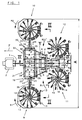
- FIG. 1 the basic structure of an inventive Haymaking machine can be seen over a trestle 1 on an agricultural tractor 2 is coupled.
- Support frame 3 which is pivotable about a vertical axis is connected to the trestle 1.
- a chassis 4 which is equipped with wheels 5,6,7,8.
- the haymaking machine includes front rotary rakes 9,10 and rear rotary rakes 11,12, the support frame 3 are assigned in a V-shaped arrangement and about itself the driving and working direction F of the haymaking machine adapting training wheels Support 13 against the ground.
- the rotary rakes 9,10,11,12 in turn have tines 14 stocked Tine arms 15 on which within a gyro housing 16 are stored and from a non-illustrated Control cam within the gyro 16 are controllable.
- all rotary rakes 9,10,11,12 be executed so that from the outer Tines 14 of the tine arms 15 described diameter are the same size or only the front Rotary rake 9,10 and the rear rotary rakes 11.12 have the same diameter.
- the rotary rakes 9,10,11,12 provided with tine arms 15, the tines 14 in use describe equal diameter.
- a haymaking machine can be a continuous area with a total working width A be edited, the total working width A in a range of 12 to 15 m or can still lie over it.
- the direction of rotation of the rotary rakes 9,10,11,12 corresponds to the respective direction of rotation arrows R1 and R2, so that in the middle behind the rear inner rotary rake 11,12 a swath filed can be for a subsequent mission Large machines such as Feldhburgseler or the like. the right size.
- the front rotary rakes 9,10 on support and drive assemblies 17,18 at articulation points 19,20 two transverse to Travel and working direction F displaceable on the supporting frame 3 of the haymaking machine supported sliding frame 21,22 in the direction of travel and direction F directed Swivel axes 23,24 stored and can thus by a Pivoting movement about the pivot axes 23,24 from a ground parallel working and operating position in one at least approximately vertical transport position and back be transferred.
- the carrying and driving arrangements 17,18 are, as this particular from Fig.2 and Figure 3 is seen, designed as an angle lever, wherein the long legs 25 of the support and drive assemblies 17,18 formed variable in length are.
- hydraulic piston-cylinder assemblies 26,27 are provided for changing the length of the long legs 25.
- hydraulic piston-cylinder assemblies 26,27 are simultaneously or temporally offset with hydraulic piston-cylinder arrangements 28,29 for the transfer of the rotary rakes 9,10 from the Work and operating position in a transport position and back from a hydraulic power source with Pressure medium can be applied.
- the support and drive assemblies 17,18 so formed be, as disclosed in DE 197 16 379 C1.
- the sash 21,22 and the receiving pockets 32,33,34,35 slide guides 21,22,32,33,34,35.
- the receiving pockets are 32, 33 and 34, 35 mounted one above the other, so that thereby a longer and thus better guidance of the carrier 30 in the receiving pockets 32,33,34,35 can be reached.
- the receiving pockets 32,33 and 34,35 next to each other, so that then the sliding frames 21,22 are designed to be identical can.
- carrier 30th To ensure the sliding frame 21,22, the inner sides the receiving pockets 32,33,34,35 with plate-shaped, preferably made of a resistant Plastic-made guide rails fitted, the over the entire length of the receiving pockets 32,33,34,35 extend.
- the guide rails can be split, with one first section at the outer ends of the receiving pockets 32,33,34,35 and a second section on the straps 30 of the sliding frame 21,22 are attached.
- Fig.1 comprises the rear part of the haymaking machine more rotary rakes 11,12, which also about support and drive assemblies 40.41 in driving and working direction F directed Schenkachsen 42,43 pivotally mounted on the support frame 3 are stored and thus by a pivoting movement from the ground-parallel working and operating position in an approximately vertical transport position and can be transferred back.
- the support and drive assemblies 40,41 also formed variable in length.
- the haymaking machine by a four wheels 5,6,7,8 encompassende Tandem axle 44 supported against the ground, wherein the tandem axle 44 via support arms 45,46 on the support frame 3 is pivotally mounted and the wheels 5,6,7,8 at around a horizontal and transverse to the driving and Working direction F directed axis pivotally mounted Achsschwingen 47 are articulated.
- This can the support frame 3 of the haymaking machine from a Work and operating position and a high stability permitting minimal ground clearance Basic position in a greater ground clearance having Raised position and thus in an advantageous Way in concrete individual situations with a larger one Ground clearance are operated while the haymaking machine usually in a position with the lowest possible Ground clearance and the greatest possible stability remains.
- a change in the ground clearance of the Haymaking machine can be over between the support frame 3 and the support arms 45,46 extending hydraulic Piston-cylinder assemblies 48,49 done.
- the rear wheels 7.8 of the tandem axle 44th a reduced relative to the front wheels 5.6 Have track width, whereby the space between the front rotary rake 9,10 and the rear rotary rake 11,12 to a minimum and thus the overall length the haymaking machine are kept small can.
- the Haymaking machine on a drive concept in which one approximately midway between the front rotary rakes 9,10 and the rear rotary rake 11,12 on the support frame 3 arranged central drive unit 50 with an output for each rotary rakes 9,10,11,12 provided is.
- the central drive unit 50 includes Gear units 51,52,53,54,55, which is characterized by a Distinguish modular construction.
- gear units 51,52,54,55 can be a structurally identical, for example from a bevel gear shaft, a gear cover and Bearings existing mounting unit 58 are used.
- drive shafts 59,60,61,62 are provided, which in another possible embodiment be replaced by a through shaft could.
Abstract
Description
Die Erfindung bezieht sich auf eine Heuwerbungsmaschine, insbesondere zum Schwaden von
landwirtschaftlichem Halm- und Blattgut, wie beispielsweise Heu, Stroh oder angewelktem
Grüngut gemäß dem Oberbegriff des Anspruches 1. Eine solche Heuwerbungsmaschine umfasst
vier umlaufend angetriebene Kreiselrechen oder dgl. Rechelemente und dient der Bildung
eines mittig hinter den Kreiselrechen abgelegten Schwades. In der heutigen Zeit werden
in der Praxis immer höhere Leistungsanforderungen gestellt, um auch weiterhin einen
wirtschaftlichen Einsatz derartiger Heuwerbungsmaschinen sowie den diesen nachfolgenden
Maschinen und Geräten, wie Häckslern oder dgl. zu gewährleisten. Die Vergrößerung der
Arbeitsbreite einer solchen Heuwerbungsmaschine stellt eine Möglichkeit zur Bereitstellung
höherer Leistungen dar, wobei eine Vergrößerung der Arbeitsbreite jedoch mit großen konstruktiven
Anstrengungen verbunden ist, beispielsweise bei der Umstellung zwischen einer
Arbeits- und Betriebsstellung und einer durch gesetzlich vorgeschriebene Abmessungen (maximale
Transporthöhe und -breite) vorgegebene Transportstellung oder bei der Realisierung
kostengünstiger und bedienerfreundlicher Antriebskonzepte.The invention relates to a haymaking machine, in particular for swathing
agricultural stalk and leaf material, such as hay, straw or wilted
Green waste according to the preamble of
Bei einer, aus einer eigenen älteren DE 197 16 379 C1 bekannten Heuwerbungsmaschine sind die zwei vorderen, äußeren der insgesamt vier Kreiselrechen über längenveränderliche Trag- und Antriebsanordnungen um in Fahrt- und Arbeitsrichtung gerichtete Achsen schwenkbar an einem über Laufräder gegenüber dem Erdboden abgestützten Tragrahmen schwenkbar gelagert. Die Trag- und Antriebsanordnungen der vorderen Kreiselrechen sind dabei so gestaltet bzw. am Tragrahmen angelenkt, dass zum einen durch die durch eine Schwenkbewegung erreichbare Überführung der vorderen Kreiselrechen aus der nahezu vertikalen Transportstellung in eine bodenparallele Arbeits- und Betriebsstellung und eine zeitlich überlagerte oder nachgeschaltete Verlängerung der Trag- und Antriebsanordnungen bereits eine Arbeitsbreite zur Verfügung gestellt wird, bei der aufgrund der minimalen Längen der Trag- und Antriebsanordnungen bzw. der Durchmesser der Kreiselrechen in der Transportstellung die für den Straßentransport zulässigen maximalen Höhen (Grenzwerte) erreicht sind. Ein Mangel der vorstehend beschriebenen Heuwerbungsmaschine ist darin zu sehen, dass eine weitere Vergrößerung der Arbeitsbreite nicht mehr möglich ist.In one, from a separate older DE 197 16 379 C1 known haymaking machine are the two front, outer of the four rotary rakes over variable length and drive assemblies to pivot in the direction of travel and working axes a supported via wheels against the ground supporting frame pivotally mounted. The support and drive arrangements of the front rotary rakes are designed this way or hinged to the support frame, that on the one hand by the achievable by a pivoting movement Transfer of the front rotary rake from the almost vertical transport position in a floor-parallel working and operating position and a temporally superimposed or Downstream extension of the support and drive assemblies already a working width is made available, due to the minimum lengths of the support and drive assemblies or the diameter of the rotary rakes in the transport position for the Road transport allowed maximum heights (limits) are reached. A lack of The haymaking machine described above can be seen in that further enlargement the working width is no longer possible.
In der DE 298 18 457 U1 wird eine landwirtschaftliche Bearbeitungsmaschine offenbart, bei der über an einem Tragrahmen angelenkten Querträgem Werkzeugträger zur Bearbeitung von Erntegut und/oder Boden angebracht sind. Ein derartiger Querträger besteht dazu aus einem Innenarm und einem Außenarm, wobei Innenarm und Außenarm über ein Gelenk mit einer in Fahrt- und Arbeitsrichtung der Bearbeitungsmaschine weisenden Achse schwenkbar miteinander verbunden sind. Der Innenarm des Querträgers seinerseits ist ebenfalls schwenkbar um eine in Fahrtrichtung gerichtete Achse am Tragrahmen, angelenkt. Zur Einleitung einer Schwenkbewegung des Innenarms ist eine Hebezylindereinheit vorgesehen, während zur Einleitung einer Schwenkbewegung des Außenarms eine Schwenkzylindereinheit dient, wobei Hebezylinder- und Schwenkzylindereinheit sowohl zur Überführung der Werkzeugträger aus der Arbeits- und Betriebsstellung in die Transportstellung oder umgekehrt als auch zur Veränderung der jeweiligen Arbeitsbreite in einer vorgegebenen Reihefolge hydraulisch anzusteuern sind. Das bedeutet, dass die Bewegungen des Innenarms und des Außenarms der Querträger voneinander abhängig sind, so dass ein Nichtbeachten der Reihenfolge Bedienungsfehler zur Folge hat und somit die Bedienerfreundlichkeit beeinträchtigt ist. In DE 298 18 457 U1 an agricultural processing machine is disclosed in The articulated on a support frame cross member tool carrier for machining Crop and / or soil are attached. Such a cross member consists of a Inner arm and an outer arm, with inner arm and outer arm via a joint with a in Driving and working direction of the processing machine facing axis pivotally with each other are connected. The inner arm of the cross member in turn is also pivotable about a directed in the direction of travel axis on the support frame, hinged. To initiate a Pivoting movement of the inner arm is a lifting cylinder unit provided while to initiate a pivoting movement of the outer arm is a pivoting cylinder unit, wherein Lifting cylinder and swivel cylinder unit both for the transfer of the tool carrier the working and operating position in the transport position or vice versa and for change to hydraulically control the respective working width in a predetermined sequence are. This means that the movements of the inner arm and the outer arm of the Cross beams are interdependent, so ignoring the sequence operator error result and thus the user-friendliness is impaired.
Aufgabe der Erfindung ist es daher, eine Heuwerbungsmaschine, insbesondere zum Schwaden von landwirtschaftlichem Halm- oder Blattgut der vorstehend aufgeführten Art mit einer derartige Flächenleistung zu schaffen, durch die die in einer einen selbstfahrenden Mähaufbereiter und einen selbstfahrenden Feldhäcksler umfassenden Erntemaschinenkette noch bestehende Lücke geschlossen wird und somit ein optimaler Ernteverlauf ohne Wartezeiten zwischen den jeweiligen Komponenten der Erntemaschinenkette erreichbar ist. Die gute Schwerpunktslage der Heuwerbungsmaschine beim Straßentransport sowie eine bedienerfreundliche Handhabung bei der Umstellung von der Arbeits- und Betriebsstellung in die Transportstellung und umgekehrt sollen dabei erhalten bleiben.The object of the invention is therefore to provide a hay-making machine, in particular for the swathing of agricultural Halm or leaf material of the abovementioned To create a kind with such area performance, by the one in a self-propelled Mähaufbereiter and a self-propelled forage harvester Harvesting machine chain still existing gap closed and thus an optimal crop without Waiting times between the respective components of the Harvesting machine chain is reachable. The good center of gravity the haymaking machine for road transport as well as a user-friendly handling at the Changeover from the working and operating position to the Transport position and vice versa should be preserved stay.
Zur Lösung der gestellten Aufgabe zeichnet sich die Heuwerbungsmaschine
der vorstehend genannten Art durch die
im kennzeichnenden Teil des Anspruches 1 angegebenen
Merkmale aus. Hinsichtlich der weiteren Ausgestaltung
der Erfindung wird auf die Ansprüche 2 bis 21 verwiesen.To solve the task is characterized haymaking machine
of the aforementioned type by the
specified in the characterizing part of
Durch die Anwendung der erfindungsgemäßen Merkmale wird eine mit vier um vertikale Achsen umlaufend angetriebenen Kreiselrechen oder dgl. Rechelemente ausgerüstete Heuwerbungsmaschine, insbesondere zum Schwaden von landwirtschaftlichem Halm- oder Blattgut geschaffen, welche sich unter Beibehaltung einer guten Schwerpunktslage durch eine Arbeitsbreite und damit durch eine Flächenleistung auszeichnet, die in der heutigen Zeit von einer leistungsfähigen, beispielsweise aus einem selbstfahrenden Mähaufbereiter und einem ebenfalls selbstfahrenden Feldhäcksler gebildeten Erntemaschinenkette gefordert wird. Zur Bereitstellung solch großer Arbeitsbreiten sind nach der Erfindung Trag- und Antriebsanordnungen der vorderen Kreiselrechen jeweils an mit dem Tragrahmen verbundenen Schiebeführungen gehaltert, welche quer zur Fahrt- und Arbeitsrichtung und dabei insbesondere in horizontaler Richtung ausschiebbar ausgebildet sind. Dadurch wird es ermöglicht, zusätzlich zu bereits aus dem Stand der Technik bekannten Maßnahmen, eine Vergrößerung der Breite des von den vorderen Kreiselrechen der Heuwerbungsmaschine vorgegebenen maximal bearbeitbaren Feldstreifens zu erreichen, ohne daß dadurch eine größere und für einen Straßentransport nicht mehr zulässige Transporthöhe herbeigeführt wird. Zu den bereits bekannten Maßnahmen zählen unter anderem die Verwendung längenveränderlicher Trag- und Antriebsanordnungen oder Trag- und Antriebsanordnungen, bei denen durch eine günstige Auswahl der Schwenkachsen in Verbindung mit einer geeigneten Gestaltung eine durch eine Schwenkbewegung erreichbare Überführung der Kreiselrechen aus einer Transportstellung mit einer gesetzlich vorgegebenen Höhe in eine Arbeits- und Betriebsstellung mit einer möglichst großen Arbeitsbreite durchführbar ist. In diesem Zusammenhang sei die eigene, ältere DE 197 16 379 C1 erwähnt, in der die vorstehenden Trag- und Antriebsanordnungen näher beschrieben werden. In einer vorteilhaften Ausführungsform der Erfindung sind als Schwenkteile ausgebildete Anlenkstellen zwischen den Trag- und Antriebsanordnungen der vorderen Kreiselrechen und den mit dem Tragrahmen der Heuwerbungsmaschine verbundenen Schiebeführungen vorgesehen. Eine Schiebeführung in einer Ausbildung mit einem quer zur Fahrt- und Arbeitsrichtung ausgerichteten in Aufnahmetaschen geführten Schieberahmen zur Anlenkung der Trag- und Antriebsanordnungen der Kreiselrechen stellt eine konstruktiv einfache und kostengünstige Lösung darstellt. Die Schieberahmen weisen dazu eine U-förmig ausgebildete Grundform auf, so daß die freien Enden der die Schieberahmen bildenden und als viereckförmige Rohre ausgeführten Träger in die ebenfalls mit einer viereckförmigen Querschnittsform versehenen Aufnahmetaschen einsetzbar sind. Um ein nahezu verschleißfreies Gleiten der in den Aufnahmetaschen eingesetzten Träger der Schieberahmen zu gewährleisten, sind die Innenseiten der Aufnahmetaschen mit plattenförmigen, vorzugsweise aus einem widerstandsfähigen Kunststoff bestehenden Führungsleisten besetzt, die sich über die gesamte Länge der Aufnahmetaschen erstrecken.By applying the features of the invention is one with four driven around vertical axes Rotary rake or the like. Equipped elements Haymaking machine, in particular for steaming of agricultural Halm or Blattgut created, which while maintaining a good center of gravity through a working width and thus through area coverage distinguishes that in the present day from a powerful, for example, a self-propelled Mower conditioner and also a self-propelled Forage harvester formed harvester chain required becomes. To provide such large working widths are according to the invention support and drive assemblies the front rotary rake on each with the Support frame mounted sliding guides held transversely to the Driving and working direction and in particular in are designed pushed out horizontally. Thereby it is possible, in addition to already from the State of the art known measures, an enlargement the width of the front rotary rake the haymaking machine predetermined maximum editable Field stripe to reach without thereby a larger and no longer allowed for road transport Transport height is brought about. To the already Among other things, known measures include the use variable-length support and drive arrangements or Trag- and drive arrangements, in which by a favorable Selection of swivel axes in conjunction with a suitable design by a pivoting movement Achievable transfer of rotary rakes from one Transport position with a statutory amount in a working and operating position with a possible large working width is feasible. In this Connection is the own, older DE 197 16 379 C1 mentions in which the above support and drive arrangements be described in more detail. In an advantageous Embodiment of the invention are formed as pivoting articulation between the support and drive arrangements of the front Rotary rake and the one with the support frame of the haymaking machine provided sliding guides provided. A sliding guide in a training with a transversely to the travel and working direction aligned in receiving pockets Guided sliding frame for articulation of Support and drive arrangements of rotary rakes provides a constructively simple and inexpensive solution represents. The sliding frames have a U-shaped design Basic shape, so that the free ends of the the sliding frame forming and as square tubes executed carrier in the likewise with a quadrangular Cross-sectional shape receiving pockets can be used. To a nearly wear-free gliding the carrier used in the receiving pockets of the To ensure sliding frames are the insides the receiving pockets with plate-shaped, preferably made of a durable plastic guide rails Occupied over the entire length the receiving pockets extend.
Um sowohl in der Arbeits- und Betriebsstellung als auch in der Transportstellung eine gute Schwerpunktslage der Heuwerbungsmaschine zu erreichen, ist die Anbringungshöhe der Schiebeführungen am Tragrahmen der Heuwerbungsmaschine bzw. der in Fahrt- und Arbeitsrichtung ausgerichteten Schwenkachsen der Anlenkstellen an den Schiebeführungen so gewählt, daß unterhalb der Schiebeführungen nur eine beim Einsatz der Heuwerbungsmaschine auf dem Feld erforderliche Mindestbodenfreiheit verbleibt. Diese Mindestbodenfreiheit ist dazu so bemessen, daß unterhalb der Schiebeführungen lediglich soviel Freiraum vorhanden ist, daß breitgestreutes Halm- und Blattgut sich nicht an den Schieberahmen aufhängt und dann von diesen mitgeschleift wird. Zur Überwindung größerer Bodenunebenheiten oder von bereits fertiggestellten Erntegutschwaden auf dem Vorgewende ist nach der Erfindung eine Achse vorgesehen, mit der der Tragrahmen der Heuwerbungsmaschine aus einer eine Arbeits- und Betriebsstellung und eine große Standfestigkeit mit minimaler Bodenfreiheit zulassenden Grundstellung in eine eine größere Bodenfreiheit aufweisende Stellung anhebbar ausgebildet ist. Somit kann die Heuwerbungsmaschine in vorteilhafter Weise in konkreten Einzelsituationen auf eine größere Bodenfreiheit angehoben werden, während die Heuwerbungsmaschine im Normalfall mit geringstmöglicher Bodenfreiheit und größstmöglicher Standfestigkeit betrieben werden kann. Gemäß einer Weiterbildung der Erfindung handelt es sich bei der zur Abstützung der Heuwerbungsmaschine gegenüber dem Erdboden verwendeten Achse um eine je Maschinenseite mit zwei hintereinander angeordneten Laufrädern bestückten Tandemachse, welche über schwenkbar am Tragrahmen gelagerte Tragarme mit diesem verbunden ist. Der Einsatz einer Tandemachse bringt zum einen ein besseres Fahrverhalten auf der Straße und zum anderen eine Reduzierung der Stützkräfte der Laufräder auf dem Erdboden. Zur Veränderung der Bodenfreiheit der Heuwerbungsmaschine sind vorzugsweise hydraulische Kolben-Zylinder-Anordnungen vorgesehen, welche sich zwischen den Tragarmen der Tandemachse und dem Tragrahmen erstrecken. Ein weiterer vorteilhafter Aspekt der Erfindung ist in der Anordnung der Laufräder der Tandemachse zu sehen. Dabei weisen die hinteren Laufräder der Tandemachse eine verminderte Spurbreite auf, so daß dadurch der erforderliche Freiraum für die Tandemachse zwischen den vorderen und hinteren Kreiselrechen der Heuwerbungsmaschine möglichst gering gehalten werden kann, d.h. durch die verminderte Spurbreite der hinteren Laufräder der Tandemachse kann, in Fahrt- und Arbeitsrichtung gesehen der Abstand zwischen den vorderen und den hinteren Kreiselrechen und damit die Gesamtabmessungen (Länge) der Heuwerbungsmaschine klein gehalten werden.To work both in the working and operating position as well in the transport position a good center of gravity of the To reach haymaking machine is the mounting height the sliding guides on the support frame of the haymaking machine or in the driving and working direction aligned pivot axes of the articulation points the sliding guides chosen so that below the sliding guides only one when using the haymaking machine on the field required minimum ground clearance remains. This minimum ground clearance is designed to that below the sliding guides only so much Freiraum exists that broadly scattered straw and Sheet material does not hang on the sliding frame and then be dragged along by them. To overcome larger ones Uneven floors or already finished Erntegutschwaden on the headland is after the invention provides an axis with which the support frame the haymaking machine from a working and operating position and a high level of stability with minimum ground clearance permitting basic position in a greater ground clearance position is designed liftable. Thus, the haymaking machine in an advantageous manner in concrete individual situations be raised to a greater ground clearance, while the haymaking machine usually with lowest possible ground clearance and the largest possible Stability can be operated. According to a development the invention is in the Supporting the haymaking machine against the ground axis used by one per machine side equipped two consecutively arranged wheels Tandem axle, which is pivotally mounted on the support frame Support arms is connected to this. The use a tandem axle brings on the one hand a better handling on the road and on the other a reduction the supporting forces of the wheels on the ground. To change the ground clearance of the haymaking machine are preferably hydraulic piston-cylinder arrangements provided, which is located between the support arms of the tandem axle and the support frame. Another Advantageous aspect of the invention is in the arrangement to see the wheels of the tandem axle. Show the rear wheels of the tandem axle a diminished Track width, so that thereby the required space for the tandem axle between the front and rear Rotary harrow of the haymaking machine possible can be kept low, i. through the diminished Track width of the rear wheels of the tandem axle, seen in driving and working direction, the distance between the front and the rear rotary rake and hence the overall dimensions (length) of the haymaking machine kept small.
Ein kostengünstiges und sich durch eine einfache Handhabung bei der Überführung der Kreiselrechen der Heuwerbungsmaschine aus einer Arbeits- und Betriebsstellung in eine Transportstellung und umgekehrt auszeichnendes Antriebskonzept ergibt sich durch die Anbringung einer zentralen Antriebseinheit, welche für jeden Kreiselrechen einen Abtrieb aufweist und auf dem Tragrahmen so angeordnet ist, daß eine für einen störungfreien Antrieb erforderliche räumliche Zuordnung zu den Eingangsgetrieben der Trag- und Antriebsanordnungen der Kreiselrechen sowohl in der Arbeits- und Betriebsstellung als auch in der Transportstellung gegeben ist. Das bedeutet, daß die Anordnung der zentalen Antriebseinheit so gewählt ist, daß die Eingangsgetriebe der Trag- und Antriebsanordnungen der Kreiselrechen über Gelenkwellen von der zentralen Antriebseinheit mit Antriebsenergie versorgt werden können, wobei die Beugungswinkel der Kreuzgelenke der Gelenkwellen sowohl in Arbeits- und Betriebsstellung als auch in der Transportstellung möglich klein gehalten werden können. In einer vorteilhaften Ausführungsform sieht die Erfindung einen sich quer zur Fahrt- und Arbeitsrichtung erstreckenden Getriebeholm vor, auf dem nebeneinander Getriebeeinheiten angebracht sind, die auf einem baugleichen Getriebegehäuse basieren und jeweils über Gelenkwellen antriebsmäßig mit einander verbunden sind.An inexpensive and easy to handle during the transfer of the rotary rakes of the haymaking machine from a work and operational position in a transport position and vice versa auszeichnendes Drive concept results from the attachment of a central drive unit, which for each rotary rake has an output and on the support frame so is arranged that one for a trouble-free drive required spatial allocation to the input gears the support and drive arrangements of the rotary rakes both in the working and operating position as is also given in the transport position. That means, that the arrangement of the central drive unit so is chosen that the input gear of the support and drive assemblies the rotary rake about drive shafts from the central drive unit with drive power can be supplied, the diffraction angle of the Universal joints of cardan shafts in both work and Operating position as well as in the transport position possible can be kept small. In an advantageous Embodiment, the invention sees a transverse to the direction of travel and working extending transmission beam before, on the side by side gear units are mounted on an identical gear housing are based and in each case via drive shafts drivingly are connected with each other.
Zur Verstellung der Breite des von den vorderen Kreiselrechen der Heuwerbungsmaschine vorgegebenen Feldstreifens d.h. zur Verschiebung der Schieberahmen in den Aufnahmetaschen der Schiebeführungen bzw. zur Arretierung der Schieberahmen der Schiebeführungen in einer gewählten Position (Arbeitsbreite) sind als hydraulische Kolben-Zylinder-Anordnungen ausgeführte, eine Zug- und Druckkraft erzeugende Stellglieder vorgesehen, wobei zur zuverlässigen Festlegung bzw. Beibehaltung einer gewählten Arbeitsbreite den hydraulischen Kolben-Zylinder-Anordnungen beispielsweise Sperrventile vorgeschaltet sein können. Um eine saubere und zuverlässige Übergabe des von den vorderen Kreiselrechen zusammengeführten Erntegutes an die hinteren Kreiselrechen gewährleisten zu können, ist eine Überdeckung der Einzelarbeitsbreiten der vorderen und hinteren Kreiselrechen erforderlich. Aus diesem Grund kann es zweckmäßig sein, daß bei Veränderungen der Arbeitsbreite der gesamten Heuwerbungsmaschine gleichzeitig eine Verschiebung in den Schiebeführungen (seitlich gerichtete Änderung der Arbeitsposition der vorderen Kreiselrechen) und eine beispielsweise durch eine Veränderung der Länge der Trag- und Antriebsanordnungen erreichbare Veränderung der Arbeitsposition der hinteren Kreiselrechen durchführbar ist.To adjust the width of the front rotary rake the haymaking machine predetermined field strip i.e. for shifting the sliding frame in the receiving pockets the sliding guides or for locking the sliding frame of the sliding guides in a selected position (working width) are considered hydraulic Piston-cylinder arrangements executed, one Tensile and compressive force generating actuators provided being for reliable determination or retention a selected working width the hydraulic Piston-cylinder arrangements, for example, check valves can be upstream. To be a clean and reliable Transfer of the merged from the front rotary rake Harvested goods at the rear rotary rakes to be able to guarantee is an overlap of the individual working widths the front and rear rotary rakes required. For this reason, it may be appropriate be that with changes in the working width of the entire Haymaking machine at the same time a shift in the sliding guides (laterally changing the working position the front rotary rake) and one example by changing the length of the support and drive arrangements achievable change in the working position the rear rotary rake feasible is.
Eine detaillierte Beschreibung des Gegenstandes der Erfindung erfolgt nun anhand eines Ausführungsbeispieles. In der Zeichnung stellt im einzelnen dar:
- Fig.1
- eine Draufsicht einer erfindungsgemäßen Heuwerbungsmaschine in einer Arbeits- und Betriebsstellung;
- Fig.2
- eine Schnittdarstellung der Heuwerbungsmaschine gemäß Schnitt II-II in Fig.1, wobei ein Kreiselrechen sich in der Transportstellung und ein Kreiselrechen sich in der Arbeits- und Betriebsstellung befindet;
- Fig.3
- eine vergrößerte, teilweise abgebrochene Darstellung der Einzelheit X in Fig.2;
- Fig.4
- eine Schnittdarstellung der Heuwerbungsmaschine gemäß Schnitt IV-IV in Fig.1 mit in Transportstellung überführten Kreiselrechen;
- Fig.5
- eine vergrößerte, teilweise abgebrochene Darstellung der Einzelheit Y in Fig.1;
- Fig.1
- a plan view of a haymaking machine according to the invention in a working and operating position;
- Fig.2
- a sectional view of the haymaking machine according to section II-II in Figure 1, wherein a rotary rake in the transport position and a rotary rake is in the working and operating position;
- Figure 3
- an enlarged, partially broken view of the detail X in Figure 2;
- Figure 4
- a sectional view of the haymaking machine according to section IV-IV in Figure 1 with transferred into transport position rotary rake;
- Figure 5
- an enlarged, partially broken representation of the detail Y in Figure 1;
Aus der Fig. 1 ist der Grundaufbau einer erfindungsgemäßen
Heuwerbungsmaschine ersichtlich, die über einen Anbaubock
1 an einem landwirtschaftlichen Zugfahrzeug 2
angekuppelt ist. An den Anbaubock 1 schließt sich ein
Tragrahmen 3 an, der um eine vertikale Achse schwenkbar
mit dem Anbaubock 1 verbunden ist. Etwa im mittleren
Bereich des Tragrahmens 3 befindet sich zur Abstützung
des Tragrahmens 3 gegenüber dem Erdboden ein Fahrwerk
4, das mit Laufrädern 5,6,7,8 bestückt ist. Desweiteren
umfaßt die Heuwerbungsmaschine vordere Kreiselrechen
9,10 und hintere Kreiselrechen 11,12, die dem Tragrahmen
3 in einer V-förmigen Anordnung zugeordnet sind und
sich über sich selbsttätig der Fahrt- und Arbeitsrichtung
F der Heuwerbungsmaschine anpassenden Stützrädern
13 gegenüber dem Erdboden abstützen. Die Kreiselrechen
9,10,11,12 ihrerseits weisen mit Zinken 14 bestückte
Zinkenarme 15 auf, die innerhalb eines Kreiselgehäuses
16 gelagert sind und von einer nicht näher dargestellten
Steuerkurve innerhalb des Kreiselgehäuses 16
steuerbar sind. Grundsätzlich können alle Kreiselrechen
9,10,11,12 so ausgeführt sein, daß die von den äußeren
Zinken 14 der Zinkenarme 15 beschriebenen Durchmesser
gleich groß ausgebildet sind oder jeweils nur die vorderen
Kreiselrechen 9,10 und die hinteren Kreiselrechen
11,12 gleiche Durchmesser aufweisen. Beim dargestellten
Ausführungsbeispiel sind die Kreiselrechen 9,10,11,12
mit Zinkenarmen 15 versehen, deren Zinken 14 im Einsatz
gleich große Durchmesser beschreiben. Mit einer Heuwerbungsmaschine
gemäß dem dargestellten Ausführungsbeispiel
kann eine durchgehende Fläche mit einer Gesamtarbeitsbreite
A bearbeitet werden, wobei die Gesamtarbeitsbreite
A in einem Bereich von 12 bis 15 m oder
noch darüber liegen kann.Die Drehrichtung der Kreiselrechen
9,10,11,12 entspricht dabei den jeweiligen Drehrichtungspfeilen
R1 und R2, so daß mittig hinter den
hinteren inneren Kreiselrechen 11,12 ein Schwad abgelegt
werden kann, das für einen Einsatz nachfolgender
Großmaschinen wie beispielweise Feldhäckseler oder dgl.
die richtige Größe aufweist.From Fig. 1, the basic structure of an inventive
Haymaking machine can be seen over a
Wie weiterhin aus der Fig.1 zu ersehen ist, sind die
vorderen Kreiselrechen 9,10 über Trag- und Antriebsanordnungen
17,18 an Anlenkstellen 19,20 zweier quer zur
Fahrt- und Arbeitsrichtung F verschiebbar am Tragrahmen
3 der Heuwerbungsmaschine gehalterter Schieberahmen
21,22 um in Fahrt- und Arbeitsrichtung F gerichtete
Schwenkachsen 23,24 gelagert und können somit durch eine
Schwenkbewegung um die Schwenkachsen 23,24 aus einer
bodenparallelen Arbeits- und Betriebsstellung in eine
zumindest annähernd vertikale Transportstellung und zurück
überführt werden. Die Trag- und Antriebsanordnungen
17,18 sind dabei, wie dies insbesondere aus Fig.2
und Fig.3 ersichtlich ist, als Winkelhebel ausgebildet,
wobei die langen Schenkel 25 der Trag- und Antriebsanordnungen
17,18 in ihrer Länge veränderlich ausgebildet
sind. Zur Veränderung der Länge der langen Schenkel 25
sind hydraulische Kolben-Zylinder-Anordnungen 26,27 vorgesehen,
wobei diese gleichzeitig oder zeitlich versetzt
mit hydraulischen Kolben-Zylinder-Anordnungen
28,29 zur Überführung der Kreiselrechen 9,10 aus der
Arbeits- und Betriebsstellung in eine Transportstellung
und zurück von einer hydraulischen Antriebsquelle mit
Druckmittel beaufschlagt werden können.Abweichend
und/oder ergänzend zu den vorstehenden Ausführungen können
die Trag- und Antriebsanordnungen 17,18 so ausgebildet
sein, wie es in der DE 197 16 379 C1 offenbart ist.As can be seen further from Fig.1, the
front rotary rakes 9,10 on support and drive
In einer vorteilhaften Ausführungsform sind die Schieberahmen
21,22 aus viereckförmigen (rechteckförmigen) Trägern
30,31 zu einer U-förmig ausgebildeten Grundform
zusammengesetzt, wobei die Träger 30 in Aufnahmetaschen
32,33,34,35 quer zur Fahrt- und Arbeitsrichtung F verschiebbar
geführt sind. Zusammen ergeben Schieberahmen 21,22 und die Aufnahmetaschen 32,33,34,35 Schiebeführungen 21,22,32,33,34,35. Wie insbeondere aus Fig.2 und 3
hervorgeht, sind die Aufnahmetaschen 32,33 und 34,35
übereinander angebracht, so daß dadurch eine längere
und damit bessere Führung der Träger 30 in den Aufnahmetaschen
32,33,34,35 erreichbar ist. In einer Weiterbildung
ist es aber auch vorstellbar, die Aufnahmetaschen
32,33 und 34,35 nebeneinander anzuordnen, so daß
dann die Schieberahmen 21,22 baugleich gestaltet werden
können. Um ein nahezu verschleißfreies Gleiten der in
den Aufnahmetaschen 32,33,34,35 eingesetzten Träger 30
der Schieberahmen 21,22 zu gewährleisten, sind die Innenseiten
der Aufnahmetaschen 32,33,34,35 mit plattenförmigen,
vorzugsweise aus einem widerstandsfähigen
Kunststoff gefertigten Führungsleisten bestückt, die
sich über die gesamte Länge der Aufnahmetaschen
32,33,34,35 erstrecken. In einer weiteren Ausführungsform
können die Führungsleisten geteilt sein, wobei ein
erster Abschnitt an den äußeren Enden der Aufnahmetaschen
32,33,34,35 und ein zweiter Abschnitt an den Trägern
30 der Schieberahmen 21,22 angebracht sind. Zur
Verschiebung der Schieberahmen 21,22 in den Aufnahmetaschen
32,33,34,35 bzw. zur Arretierung der Schieberahmen
21,22 in eine ausgewählten Arbeitsbreite sind nach
der Erfindung den Schiebeführungen 21,22,32,33,34,35 Zug- und Druckkraft erzeugende Stellglieder
36,37 zugeordnet, wobei diese vorzugsweise als hydraulische
Kolben-Zylinder-Anordnungen 38,39 ausgeführt
sind.In an advantageous embodiment, the sliding
Wie weiterhin aus der Fig.1 zu entnehmen ist, umfaßt
der hintere Teil der Heuwerbungsmaschine weitere Kreiselrechen
11,12, welche ebenfalls über Trag- und Antriebsanordnungen
40,41 um in Fahrt- und Arbeitsrichtung
F gerichtete Schenkachsen 42,43 schwenkbar am Tragrahmen
3 gelagert sind und somit durch eine Schwenkbewegung
aus der bodenparallelen Arbeits- und Betriebsstellung
in eine in etwa vertikale Transportstellung und
zurück überführt werden können. Zur Anpassung an die
Arbeitsbreiteneinstellung der vorderen Kreiselrechen
9,10 an die Breiteneinstellung der hinteren Kreiselrechen
11,12 sind die Trag- und Antriebsanordnungen 40,41
ebenfalls längenveränderlich ausgebildet.As can be further seen from Fig.1, comprises
the rear part of the haymaking machine more rotary rakes
11,12, which also about support and drive assemblies
40.41 in driving and working direction
F directed
Wie aus den Fig. 4 und 5 hervorgeht, ist die Heuwerbungsmaschine
durch eine vier Laufräder 5,6,7,8 umfaßende
Tandemachse 44 gegenüber dem Erdboden abgestützt,
wobei die Tandemachse 44 über Tragarme 45,46 am Tragrahmen
3 schwenkbar gehaltert ist und die Laufräder
5,6,7,8 an um eine horizontal und quer zur Fahrt- und
Arbeitsrichtung F gerichtete Achse schwenkbar gelagerten
Achsschwingen 47 angelenkt sind. Dadurch kann
der Tragrahmen 3 der Heuwerbungsmaschine aus einer eine
Arbeits- und Betriebsstellung und eine große Standfestigkeit
mit minimaler Bodenfreiheit zulassenden
Grundstellung in eine eine größere Bodenfreiheit aufweisende
Stellung angehoben und damit in vorteilhafter
Weise in konkreten Einzelsituationen mit einer größeren
Bodenfreiheit betrieben werden, während die Heuwerbungsmaschine
im Normalfall in einer Stellung mit geringstmöglicher
Bodenfreiheit und größstmöglicher Standfestigkeit
verbleibt. Eine Veränderung der Bodenfreiheit der
Heuwerbungsmaschine kann über sich zwischen dem Tragrahmen
3 und den Tragarmen 45,46 erstreckenden hydraulische
Kolben-Zylinder-Anordnungen 48,49 erfolgen. Eine
weitere vorteilhafte Weiterbildung der Erfindung sieht
vor, daß die hinteren Laufräder 7,8 der Tandemachse 44
eine gegenüber den vorderen Laufrädern 5,6 verminderte
Spurbreite aufweisen, wodurch der Freiraum zwischen den
vorderen Kreiselrechen 9,10 und den hinteren Kreiselrechen
11,12 auf ein Minimum beschränkt und damit die Baulänge
der Heuwerbungsmaschine klein gehalten werden
kann.As is apparent from Figs. 4 and 5, the haymaking machine
by a four
Wie insbesondere aus den Fig. 1 und 5 zu entnehmen ist, weist die
Heuwerbungsmaschine ein Antriebskonzept auf, bei dem
eine in etwa mittig zwischen den vorderen Kreiselrechen
9,10 und den hinteren Kreiselrechen 11,12 auf dem Tragrahmen
3 angeordnete zentrale Antriebseinheit 50 mit
einem Abtrieb für jeden Kreiselrechen 9,10,11,12 vorgesehen
ist. Die zentrale Antriebseinheit 50 umfaßt dazu
Getriebeeinheiten 51,52,53,54,55, welche sich durch eine
Modulbauweise auszeichnen. Als Basis dient dabei für
alle Getriebeeinheiten 51,52,53,54,55 ein baugleiches
Getriebegehäuse 56, welches auf einem mit dem Tragrahmen
3 verbundenen Getriebeholm 57 gehaltert ist. Desweiteren
kann für den Getriebeeingangsbereich der Getriebeeinheit
53 sowie für den Getriebeausgangsbereich der
Getriebeeinheiten 51,52,54,55 eine baugleiche beispielsweise
aus einer Kegelradwelle, einem Getriebedeckel und
Lagern bestehenden Montageeinheit 58 eingesetzt werden.
Zur antriebsmäßigen Verbindung der Getriebeeinheiten
51,52,53,54,55 sind Gelenkwellen 59,60,61,62 vorgesehen,
welche in einer weiteren denkbaren Ausführungsform
auch durch eine Durchgangswelle ersetzt werden
könnten. Zur Antriebsübertragung von den Getriebeeinheiten
51,52,54,55 zu den Kreiselrechen 9,10,11,12 sind
weitere Gelenkwellen 63,64,65,66 eingesetzt, deren
Kreuzgelenke sowohl in der Arbeits- und Betriebsstellung
der Kreiselrechen 9,10,11,12 als auch in der Transportstellung
bedingt durch eine günstige Anordnung der
zentralen Antriebseinheit 50 mit minimalen Beugungswinkeln
betrieben werden können. Zum Antrieb der zentralen
Antriebseinheit 50 und damit der Kreiselrechen
9,10,11,12 dient ein Antriebsverbindung 67, welche sich
zwischen dem landwirtschaftlichen Zugfahrzeug 2 und der
zentralen Antriebseinheit 50 erstreckt.As can be seen in particular from FIGS. 1 and 5, the
Haymaking machine on a drive concept, in which
one approximately midway between the front rotary rakes
9,10 and the
Claims (21)
- Haymaking machine, particularly for windrowing agricultural stalk and leafed crops, having four rotary rakes (9, 10, 11, 12) or similar rake members which are driven in rotation about vertical axes, which are supported in relation to the ground by support wheels (13) and have tine arms (15) fitted with tines (14), of which at least those rotary rakes which are situated at the front in the direction of travel (F) can be moved in a horizontal direction transversely to the direction of travel (F), and the rotary rakes (9, 10, 11, 12) can be transferred from an approximately horizontal working and operating position to an at least approximately vertical transport position, and back, by means of carrier and drive arrangements (17, 18,40,41), which carrier and drive arrangements (17, 18,40,41) are mounted, on both sides of a carrier frame (3) provided with ground wheels, to be movable about pivot shafts (23, 24, 42, 43) directed in the direction of travel (F), the carrier and drive arrangements (17, 18, 40, 41) occupying a position in which they are directed outwards from the carrier frame (3) in the working and operating position and a position in which they point upwards from the carrier frame (3) in the transport position, characterised in that the hinge points (19, 20) of the carrier and drive arrangements (17, 18) for the front rotary rakes (9,10), which hinge points (19, 20) have pivot shafts (23, 24), are each mounted on mountings for sliding movement (21, 22, 32, 33, 34, 35) which are connected to the carrier frame (3), and, by means of the mountings for sliding movement (21, 22, 32, 33,34, 35), the carrier and drive arrangements (17, 18) are able to perform, together with the front rotary rakes (9, 10), a movement transversely to the direction of travel (F) which is directed substantially in a horizontal direction and outwards and back.
- Haymaking machine according to claim 1, characterised in that the mountings for sliding movement (21, 22, 32, 33, 34, 35) for mounting the carrier and drive arrangements (17, 18) comprise sliding frames (21, 22) and holding receptacles (32, 33, 34, 35), which latter are mounted on the carrier frame and aligned transversely to the direction of travel (F).
- Haymaking machine according to claim 2, characterised in that the hinge points (19, 20) of the carrier and drive arrangements (17, 18), which hinge points (19, 20) have the pivot shafts (23, 24), are mounted on the sliding frames (21, 22).
- Haymaking machine according to either of daims 2 and 3, characterised in that the sliding frames (21, 22) of the mountings for sliding movement (21, 22, 32, 33, 34, 35) are guided to be movable and lockable in the holding receptacles (32, 33, 34, 35) which are mounted on the carrier frame (3) and aligned transversely to the direction of travel (F).
- Haymaking machine according to one of daims 1 to 4, characterised in that, by means of the displacement of the sliding frames (21, 22) in the holding receptacles (32, 33, 24, 35), a stepless enlargement or reduction of the overall working width of the haymaking machine can be obtained.
- Haymaking machine according to one of daims 2 to 5, characterised in that the mountings for sliding movement (21, 22, 32, 33, 34, 35) are mounted on the carrier frame (3) in such a way that only a minimum ground clearance required for operation is left between the sliding frames (21, 22) and the ground.
- Haymaking machine according to one of daims 2 to 6, characterised in that the sliding frames (21, 22) comprise girders (30, 31) which are assembled into a basic shape of U-shaped configuration.
- Haymaking machine according to claim 7, characterised in that the cross-sectional shape of the girders (30, 31) of the sliding frames (21, 22) is that of a quadrilateral tube.
- Haymaking machine according to claim 7, characterised in that the cross-sectional shape of the holding receptacles (32, 33, 24, 25) is also that of a quadrilateral.
- Haymaking machine according to one of daims 2 to 9, characterised in that the holding receptacles (32, 34) for the sliding frame (21) are arranged above or below the holding receptacles (33, 35) for the sliding frame (22).
- Haymaking machine according to one of claims 2 to 9, characterised in that the holding receptacles (32, 34) for the sliding frame (21) and the holding receptacles (33, 35) for the sliding frame (22) are mounted next to one another.
- Haymaking machine according to one of daims 2 to 11, characterised in that actuators (36, 37) generating tractive and compressive forces are provided to move and lock the sliding frames (21, 22) in the holding receptacles (32, 33, 34, 35)
- Haymaking machine according to claim 12, characterised in that the actuators (36, 37) generating tractive and compressive forces are in the form of hydraulic piston-and-cylinder arrangements (38, 39).
- Haymaking machine according to one of daims 1 to 13, characterised in that a central drive unit (50), which has a drive output for each rotary rake (9, 10, 11, 12), is arranged on the carrier frame (3).
- Haymaking machine according to one of daims 1 to 14, characterised in that the central drive unit (50) is formed from gearbox units (51, 52, 53, 54, 55) which are arranged on a gearbox beam (57) extending transversely to the direction of travel and operation (F).
- Haymaking machine according to one of claims 1 to 15, characterised in that, looking in the direction of travel and operation (F), the gearbox beam (57) is mounted on the carrier frame between the front rotary rakes (9, 10) and the rear rotary rakes (11,12).
- Haymaking machine according to one of claims 1 to 16, characterised in that the gearbox units (51, 52, 53, 54, 55) of the central drive unit (50) have housings (56) of the same design.
- Haymaking machine according to one of daims 1 to 17, characterised in that a tandem axle (44) having ground wheels (5, 6, 7, 8) is provided to support the carrier frame (3) in relation to the ground.
- Haymaking machine according to one of daims 1 to 18, characterised in that a tandem axle (44) having ground wheels (5, 6, 7, 8) is provided to support the carrier frame (3) in relation to the ground, by which tandem axle (44) the carrier frame (3) can be raised from a basic position which permits a working and operating position and ensures high stability by virtue of minimal ground clearance, to a position in which there is greater ground clearance.
- Haymaking machine according to one of daims 1 to 19, characterised in that pivotably mounted carrier arms (45, 46), which can be operated by hydraulic piston-and-cylinder arrangements (48, 49), are provided on the carrier frame (3) to allow the tandem axle (44) and the ground wheels (5, 6, 7, 8) to be attached in such a way that height can be varied
- Haymaking machine according to one of daims 1 to 20, characterised in that the rear ground wheels (7, 8) of the tandem axle (44) are of reduced track in comparison with the front ground wheels (5, 6).
Applications Claiming Priority (2)
| Application Number | Priority Date | Filing Date | Title |
|---|---|---|---|
| DE19952555A DE19952555C2 (en) | 1999-11-01 | 1999-11-01 | Hay-making machine |
| DE19952555 | 1999-11-01 |
Publications (2)
| Publication Number | Publication Date |
|---|---|
| EP1095555A1 EP1095555A1 (en) | 2001-05-02 |
| EP1095555B1 true EP1095555B1 (en) | 2004-09-22 |
Family
ID=7927571
Family Applications (1)
| Application Number | Title | Priority Date | Filing Date |
|---|---|---|---|
| EP00122756A Expired - Lifetime EP1095555B1 (en) | 1999-11-01 | 2000-10-19 | Haymaking machine |
Country Status (3)
| Country | Link |
|---|---|
| EP (1) | EP1095555B1 (en) |
| AT (1) | ATE276645T1 (en) |
| DE (2) | DE19952555C2 (en) |
Cited By (4)
| Publication number | Priority date | Publication date | Assignee | Title |
|---|---|---|---|---|
| US9277690B2 (en) | 2010-03-08 | 2016-03-08 | Forage Innovations B.V. | Haymaking device |
| DE102018116014A1 (en) | 2018-07-02 | 2020-01-02 | Claas Saulgau Gmbh | Agricultural implement |
| EP3892085A1 (en) | 2020-04-08 | 2021-10-13 | PÖTTINGER Landtechnik GmbH | Multiple windrow and method for operating a multiple windrow |
| RU208646U1 (en) * | 2021-08-26 | 2021-12-29 | Общество с ограниченной ответственностью "Новосибирский опытно-экспериментальный завод нестандартизированного оборудования" | HAY HARVESTING DEVICE |
Families Citing this family (10)
| Publication number | Priority date | Publication date | Assignee | Title |
|---|---|---|---|---|
| FR2828988B1 (en) * | 2001-09-06 | 2004-07-30 | Kuhn Sa | FENAISON MACHINE HAVING ROTORS LINKED TO CARRIER ARMS MADE IN TWO TELESCOPIC PARTS |
| DE20207865U1 (en) | 2002-05-21 | 2003-10-02 | Kverneland Asa Kverneland | Hay-making machine |
| DE10327901C5 (en) * | 2003-06-20 | 2011-11-17 | Maschinenfabrik Bernard Krone Gmbh | Hay-making machine |
| DE10327884B4 (en) * | 2003-06-20 | 2006-01-05 | Maschinenfabrik Bernard Krone Gmbh | Hay-making machine |
| DE102004058461A1 (en) * | 2004-12-03 | 2006-06-14 | Maschinenfabrik Bernard Krone Gmbh | Hay-making machine |
| DE102007053566A1 (en) * | 2007-11-09 | 2009-05-14 | Alois Pöttinger Maschinenfabrik Gmbh | Hay-making machine |
| NL1037782C2 (en) | 2010-03-08 | 2011-09-09 | Forage Innovations Bv | HAY BUILDING DEVICE. |
| NL1037785C2 (en) | 2010-03-08 | 2011-09-09 | Forage Innovations Bv | HAY BUILDING DEVICE. |
| DE102016012522A1 (en) * | 2016-10-20 | 2018-04-26 | Maschinenfabrik Bernard Krone GmbH & Co. KG | Haymaking machine with modular attachment |
| DE102019104755A1 (en) * | 2019-02-25 | 2020-08-27 | Horsch Maschinen Gmbh | Soil cultivation machine, in particular hoe |
Family Cites Families (6)
| Publication number | Priority date | Publication date | Assignee | Title |
|---|---|---|---|---|
| DE4405858C1 (en) * | 1994-02-23 | 1995-06-01 | Fortschritt Erntemaschinen | Mower with wide working width |
| DE29521619U1 (en) * | 1995-12-15 | 1997-11-27 | Claas Saulgau Gmbh | Rotary rakes |
| FR2759245B1 (en) * | 1997-02-11 | 1999-04-23 | Kuhn Sa | FENAISON MACHINE WITH A GROUND SUPPORT DEVICE INCLUDING AT LEAST A BALANCER WITH TWO CARRIER WHEELS AND A MEANS FOR MOVING THIS BALANCER FOR TRANSPORT |
| DE19716379C1 (en) * | 1997-04-18 | 1998-06-18 | Krone Bernhard Gmbh Maschf | Agricultural harvester machine for standing crops |
| NL1006945C2 (en) * | 1997-09-04 | 1999-03-05 | Arend Mulder | Tool carrier. |
| DE29818457U1 (en) * | 1998-10-15 | 1998-12-17 | Multinorm Bv | Agricultural processing machine |
-
1999
- 1999-11-01 DE DE19952555A patent/DE19952555C2/en not_active Expired - Fee Related
-
2000
- 2000-10-19 EP EP00122756A patent/EP1095555B1/en not_active Expired - Lifetime
- 2000-10-19 AT AT00122756T patent/ATE276645T1/en active
- 2000-10-19 DE DE50007864T patent/DE50007864D1/en not_active Expired - Lifetime
Cited By (4)
| Publication number | Priority date | Publication date | Assignee | Title |
|---|---|---|---|---|
| US9277690B2 (en) | 2010-03-08 | 2016-03-08 | Forage Innovations B.V. | Haymaking device |
| DE102018116014A1 (en) | 2018-07-02 | 2020-01-02 | Claas Saulgau Gmbh | Agricultural implement |
| EP3892085A1 (en) | 2020-04-08 | 2021-10-13 | PÖTTINGER Landtechnik GmbH | Multiple windrow and method for operating a multiple windrow |
| RU208646U1 (en) * | 2021-08-26 | 2021-12-29 | Общество с ограниченной ответственностью "Новосибирский опытно-экспериментальный завод нестандартизированного оборудования" | HAY HARVESTING DEVICE |
Also Published As
| Publication number | Publication date |
|---|---|
| ATE276645T1 (en) | 2004-10-15 |
| DE19952555C2 (en) | 2003-08-07 |
| DE50007864D1 (en) | 2004-10-28 |
| DE19952555A1 (en) | 2001-05-10 |
| EP1095555A1 (en) | 2001-05-02 |
Similar Documents
| Publication | Publication Date | Title |
|---|---|---|
| EP0872170B1 (en) | Haymaking machine | |
| DE60309623T2 (en) | mower | |
| EP2067397B1 (en) | Harvester head to gather and transport cereals in an agricultural harvesting machine | |
| EP1095555B1 (en) | Haymaking machine | |
| EP0339231A2 (en) | Agricultural mowing and hay-making machine | |
| DE2601304A1 (en) | AGRICULTURAL MACHINE WITH AT LEAST TWO AXES CIRCULATING AROUND | |
| EP0464387B1 (en) | Hay-making machine | |
| DE60210550T2 (en) | Hay-making machine | |
| DE69628598T2 (en) | Hay-making machine | |
| EP1093708A1 (en) | Mowing device | |
| DE60112351T2 (en) | Hay-making machine | |
| EP0116661A1 (en) | Mowing device | |
| DE102008042392B4 (en) | Harvesting header for agricultural harvesting machines | |
| EP0600304A1 (en) | Hay making machine | |
| EP0289864B1 (en) | Hay making machine | |
| EP0548720A2 (en) | Hay making machine | |
| DE4142496C2 (en) | Haymaking machine | |
| AT501972B1 (en) | MOWER | |
| DE4201881A1 (en) | Rotary swather with rotary rakes following curved track - has changeable position of curved track through rotation about rotary axis of rake | |
| DE4428288C2 (en) | Agricultural implement, in particular mulcher | |
| EP1597953A1 (en) | Agricultural machine | |
| DE102018118971A1 (en) | Agricultural implement | |
| DE4103011C2 (en) | Mower or hay machine | |
| EP2394505B1 (en) | Haymaking machine | |
| EP2055174B1 (en) | Self-propelled agricultural harvester |
Legal Events
| Date | Code | Title | Description |
|---|---|---|---|
| PUAI | Public reference made under article 153(3) epc to a published international application that has entered the european phase |
Free format text: ORIGINAL CODE: 0009012 |
|
| AK | Designated contracting states |
Kind code of ref document: A1 Designated state(s): AT BE CH CY DE DK ES FI FR GB GR IE IT LI LU MC NL PT SE |
|
| AX | Request for extension of the european patent |
Free format text: AL;LT;LV;MK;RO;SI |
|
| 17P | Request for examination filed |
Effective date: 20011012 |
|
| AKX | Designation fees paid |
Free format text: AT BE CH CY DE DK ES FI FR GB GR IE IT LI LU MC NL PT SE |
|
| 17Q | First examination report despatched |
Effective date: 20030814 |
|
| GRAP | Despatch of communication of intention to grant a patent |
Free format text: ORIGINAL CODE: EPIDOSNIGR1 |
|
| GRAS | Grant fee paid |
Free format text: ORIGINAL CODE: EPIDOSNIGR3 |
|
| GRAA | (expected) grant |
Free format text: ORIGINAL CODE: 0009210 |
|
| AK | Designated contracting states |
Kind code of ref document: B1 Designated state(s): AT BE CH CY DE DK ES FI FR GB GR IE IT LI LU MC NL PT SE |
|
| PG25 | Lapsed in a contracting state [announced via postgrant information from national office to epo] |
Ref country code: IT Free format text: LAPSE BECAUSE OF FAILURE TO SUBMIT A TRANSLATION OF THE DESCRIPTION OR TO PAY THE FEE WITHIN THE PRESCRIBED TIME-LIMIT;WARNING: LAPSES OF ITALIAN PATENTS WITH EFFECTIVE DATE BEFORE 2007 MAY HAVE OCCURRED AT ANY TIME BEFORE 2007. THE CORRECT EFFECTIVE DATE MAY BE DIFFERENT FROM THE ONE RECORDED. Effective date: 20040922 Ref country code: GB Free format text: LAPSE BECAUSE OF FAILURE TO SUBMIT A TRANSLATION OF THE DESCRIPTION OR TO PAY THE FEE WITHIN THE PRESCRIBED TIME-LIMIT Effective date: 20040922 Ref country code: IE Free format text: LAPSE BECAUSE OF FAILURE TO SUBMIT A TRANSLATION OF THE DESCRIPTION OR TO PAY THE FEE WITHIN THE PRESCRIBED TIME-LIMIT Effective date: 20040922 Ref country code: CY Free format text: LAPSE BECAUSE OF FAILURE TO SUBMIT A TRANSLATION OF THE DESCRIPTION OR TO PAY THE FEE WITHIN THE PRESCRIBED TIME-LIMIT Effective date: 20040922 Ref country code: FI Free format text: LAPSE BECAUSE OF FAILURE TO SUBMIT A TRANSLATION OF THE DESCRIPTION OR TO PAY THE FEE WITHIN THE PRESCRIBED TIME-LIMIT Effective date: 20040922 |
|
| REG | Reference to a national code |
Ref country code: GB Ref legal event code: FG4D Free format text: NOT ENGLISH |
|
| REG | Reference to a national code |
Ref country code: CH Ref legal event code: EP |
|
| PG25 | Lapsed in a contracting state [announced via postgrant information from national office to epo] |
Ref country code: LU Free format text: LAPSE BECAUSE OF NON-PAYMENT OF DUE FEES Effective date: 20041019 |
|
| REG | Reference to a national code |
Ref country code: IE Ref legal event code: FG4D Free format text: GERMAN |
|
| REF | Corresponds to: |
Ref document number: 50007864 Country of ref document: DE Date of ref document: 20041028 Kind code of ref document: P |
|
| PG25 | Lapsed in a contracting state [announced via postgrant information from national office to epo] |
Ref country code: LI Free format text: LAPSE BECAUSE OF NON-PAYMENT OF DUE FEES Effective date: 20041031 Ref country code: CH Free format text: LAPSE BECAUSE OF NON-PAYMENT OF DUE FEES Effective date: 20041031 Ref country code: BE Free format text: LAPSE BECAUSE OF NON-PAYMENT OF DUE FEES Effective date: 20041031 Ref country code: MC Free format text: LAPSE BECAUSE OF NON-PAYMENT OF DUE FEES Effective date: 20041031 |
|
| PG25 | Lapsed in a contracting state [announced via postgrant information from national office to epo] |
Ref country code: SE Free format text: LAPSE BECAUSE OF FAILURE TO SUBMIT A TRANSLATION OF THE DESCRIPTION OR TO PAY THE FEE WITHIN THE PRESCRIBED TIME-LIMIT Effective date: 20041222 Ref country code: GR Free format text: LAPSE BECAUSE OF FAILURE TO SUBMIT A TRANSLATION OF THE DESCRIPTION OR TO PAY THE FEE WITHIN THE PRESCRIBED TIME-LIMIT Effective date: 20041222 Ref country code: DK Free format text: LAPSE BECAUSE OF FAILURE TO SUBMIT A TRANSLATION OF THE DESCRIPTION OR TO PAY THE FEE WITHIN THE PRESCRIBED TIME-LIMIT Effective date: 20041222 |
|
| PG25 | Lapsed in a contracting state [announced via postgrant information from national office to epo] |
Ref country code: ES Free format text: LAPSE BECAUSE OF FAILURE TO SUBMIT A TRANSLATION OF THE DESCRIPTION OR TO PAY THE FEE WITHIN THE PRESCRIBED TIME-LIMIT Effective date: 20050102 |
|
| GBV | Gb: ep patent (uk) treated as always having been void in accordance with gb section 77(7)/1977 [no translation filed] |
Effective date: 20040922 |
|
| REG | Reference to a national code |
Ref country code: IE Ref legal event code: FD4D |
|
| BERE | Be: lapsed |
Owner name: MASCHINENFABRIK BERNARD KRONE G.M.B.H. Effective date: 20041031 |
|
| REG | Reference to a national code |
Ref country code: CH Ref legal event code: PL |
|
| ET | Fr: translation filed | ||
| PLBE | No opposition filed within time limit |
Free format text: ORIGINAL CODE: 0009261 |
|
| STAA | Information on the status of an ep patent application or granted ep patent |
Free format text: STATUS: NO OPPOSITION FILED WITHIN TIME LIMIT |
|
| 26N | No opposition filed |
Effective date: 20050623 |
|
| BERE | Be: lapsed |
Owner name: MASCHINENFABRIK BERNARD *KRONE G.M.B.H. Effective date: 20041031 |
|
| PG25 | Lapsed in a contracting state [announced via postgrant information from national office to epo] |
Ref country code: PT Free format text: LAPSE BECAUSE OF NON-PAYMENT OF DUE FEES Effective date: 20050222 |
|
| REG | Reference to a national code |
Ref country code: FR Ref legal event code: PLFP Year of fee payment: 16 |
|
| REG | Reference to a national code |
Ref country code: FR Ref legal event code: PLFP Year of fee payment: 17 |
|
| REG | Reference to a national code |
Ref country code: FR Ref legal event code: PLFP Year of fee payment: 18 |
|
| PGFP | Annual fee paid to national office [announced via postgrant information from national office to epo] |
Ref country code: AT Payment date: 20171010 Year of fee payment: 18 Ref country code: NL Payment date: 20171026 Year of fee payment: 18 |
|
| REG | Reference to a national code |
Ref country code: FR Ref legal event code: PLFP Year of fee payment: 19 |
|
| PGFP | Annual fee paid to national office [announced via postgrant information from national office to epo] |
Ref country code: DE Payment date: 20181018 Year of fee payment: 19 |
|
| PGFP | Annual fee paid to national office [announced via postgrant information from national office to epo] |
Ref country code: FR Payment date: 20181029 Year of fee payment: 19 |
|
| REG | Reference to a national code |
Ref country code: NL Ref legal event code: MM Effective date: 20181101 |
|
| REG | Reference to a national code |
Ref country code: AT Ref legal event code: MM01 Ref document number: 276645 Country of ref document: AT Kind code of ref document: T Effective date: 20181019 |
|
| PG25 | Lapsed in a contracting state [announced via postgrant information from national office to epo] |
Ref country code: NL Free format text: LAPSE BECAUSE OF NON-PAYMENT OF DUE FEES Effective date: 20181101 |
|
| PG25 | Lapsed in a contracting state [announced via postgrant information from national office to epo] |
Ref country code: AT Free format text: LAPSE BECAUSE OF NON-PAYMENT OF DUE FEES Effective date: 20181019 |
|
| REG | Reference to a national code |
Ref country code: DE Ref legal event code: R119 Ref document number: 50007864 Country of ref document: DE |
|
| PG25 | Lapsed in a contracting state [announced via postgrant information from national office to epo] |
Ref country code: DE Free format text: LAPSE BECAUSE OF NON-PAYMENT OF DUE FEES Effective date: 20200501 |
|
| PG25 | Lapsed in a contracting state [announced via postgrant information from national office to epo] |
Ref country code: FR Free format text: LAPSE BECAUSE OF NON-PAYMENT OF DUE FEES Effective date: 20191031 |