EP2067397B1 - Harvester head to gather and transport cereals in an agricultural harvesting machine - Google Patents
Harvester head to gather and transport cereals in an agricultural harvesting machine Download PDFInfo
- Publication number
- EP2067397B1 EP2067397B1 EP08168993A EP08168993A EP2067397B1 EP 2067397 B1 EP2067397 B1 EP 2067397B1 EP 08168993 A EP08168993 A EP 08168993A EP 08168993 A EP08168993 A EP 08168993A EP 2067397 B1 EP2067397 B1 EP 2067397B1
- Authority
- EP
- European Patent Office
- Prior art keywords
- side parts
- axis
- parts
- pivoted
- transport position
- Prior art date
- Legal status (The legal status is an assumption and is not a legal conclusion. Google has not performed a legal analysis and makes no representation as to the accuracy of the status listed.)
- Active
Links
Images

Classifications
-
- A—HUMAN NECESSITIES
- A01—AGRICULTURE; FORESTRY; ANIMAL HUSBANDRY; HUNTING; TRAPPING; FISHING
- A01D—HARVESTING; MOWING
- A01D41/00—Combines, i.e. harvesters or mowers combined with threshing devices
- A01D41/12—Details of combines
- A01D41/14—Mowing tables
- A01D41/144—Foldable headers
-
- A—HUMAN NECESSITIES
- A01—AGRICULTURE; FORESTRY; ANIMAL HUSBANDRY; HUNTING; TRAPPING; FISHING
- A01B—SOIL WORKING IN AGRICULTURE OR FORESTRY; PARTS, DETAILS, OR ACCESSORIES OF AGRICULTURAL MACHINES OR IMPLEMENTS, IN GENERAL
- A01B73/00—Means or arrangements to facilitate transportation of agricultural machines or implements, e.g. folding frames to reduce overall width
- A01B73/02—Folding frames
- A01B73/04—Folding frames foldable about a horizontal axis
- A01B73/044—Folding frames foldable about a horizontal axis the axis being oriented in a longitudinal direction
- A01B73/046—Folding frames foldable about a horizontal axis the axis being oriented in a longitudinal direction each folding frame part being foldable in itself
Definitions
- the invention relates to a harvesting attachment for agricultural harvesting machines for receiving and conveying strawberries, for example corn plants, which is movable in a forward direction over a field during harvesting operation, with an attachable to a harvester central part, two first side parts, each on a different side of the middle part about a first, horizontally and in the forward direction extending axis between a working position and a transport position pivotally articulated, and two second side parts, each on the outside at one of the first side parts about a second, horizontally and in the forward direction extending axis between a working position and a transport position are pivotally articulated, wherein the middle part and the first and second side parts in the working position laterally juxtaposed mowing and conveying elements comprise and the side parts of each side of the header g ege- or in the same direction about the associated axes between the working position and the transport position are pivotable, in which they are located above the middle part.
- DE 41 31 491 A describes a maize harvester for forage harvesters, in which the outer parts can be folded up about horizontal, in the forward direction axes.
- the side parts are pivoted about horizontal, in the forward direction axes and placed horizontally over the middle part, while in the considered as generic DE 298 17 666 U is proposed to pivot in a five-piece header, the inner side panels in the transport position vertically upwards and turn the outer side panels in contrast again inwardly in an approximately horizontal position, so that the outer side parts are arranged above the middle parts.
- the DE 103 03 380 A describes another five-piece header, in which the inner side parts are pivoted in the transport position by about 135 ° upwards and inwards, while the outer side parts are pivoted in opposite directions to the inner side parts by 180 ° to the outside.
- the working width of the header is limited by the maximum permissible height during road travel when the side parts are pivoted upwards by 90 ° ( DE 41 31 491 A ), or it is limited to twice the width permitted on the road when the side parts are pivoted inwards by 180 ° and deposited above the middle part ( EP 0 491 405 A ).
- the arrangement after DE 298 17 666 U allows larger working widths, which are also limited by height and width restrictions in road travel upwards, which also for the embodiment according to DE 103 03 380 A applies.
- the object underlying the invention is seen to provide a harvesting attachment, which allows a greater working width compared to the prior art in compliance with restrictions on the transport width and height.
- a harvesting header comprises a central part and at its lateral ends pivotally hinged about first horizontal and forward axes extending first side panels. At the outer ends of the first side parts second side parts are pivotally articulated about horizontally and in the forward direction extending second axes. At the outer ends of the second side parts in turn outer parts are hinged to horizontally and in the forward direction extending third axis.
- the central part is removably attachable to a harvester, be it rigid or a horizontal, extending in the forward direction swing axle to adjust the position of the header to ground contours, the pendulum motion is suppressed when driving on the road.
- the header therefore comprises a total of (at least) seven parts, namely the middle part, four side parts and two outer parts.
- All these parts include mowing and conveying elements for receiving and conveying plants and extend in a working position transversely to the forward direction and horizontally in a common working plane.
- the outer and side parts are pivoted about the axes mentioned in a transport position, including power-operated actuators, in particular in the form of hydraulic cylinders, are provided.
- the side parts are pivoted inwards or inwards in the same direction.
- the outer parts are also pivoted relative to the second side parts about third axes in their transport position, it being possible to pivot them in the same direction with the side parts of the associated side inwards, or in opposite directions to rotate outwards.
- the second side parts are pivoted in the transport position by 180 ° about the second axis inwardly, while the outer parts are pivoted in the transport position by 180 ° about the third axis inwardly.
- the side parts and the outer parts in the transport position take a sandwich-like configuration in which they are all oriented vertically and the outer part is located between the two side parts.
- the first side parts are furthest out and the second side parts furthest inside.
- the individual parts can be pivoted one after the other at the same time or in a suitable order avoiding a collision.
- the invention is suitable for all types of harvesting attachments, such as maize headers, corn pickers and cutting units, which can be used on self-propelled or tractor-mounted harvesting machines, especially in the form of mounted or towed or self-propelled forage harvester or combine harvesters.
- a promotion of the crop in the harvester is not mandatory, so that the invention, for example, to carrier vehicles with mowers in the form of mowing or mowing or the like. Can be used for cutting grass with pivoting side and outer parts application.
- the first side parts are oriented vertically in the transport position, d. H. They are pivoted 90 ° between the working position and the transport position.
- the second side parts are pivoted by 180 ° inwards, so that they are then oriented vertically downwards.
- FIG. 1 is a plan view of a self-propelled harvester 10 in the form of a forage harvester reproduced with a on the intake duct 12 of the harvester 10 releasably mounted header 14.
- the harvesting attachment 14 exemplified here as an embodiment of a harvesting device is designed in the form of a mowing attachment and comprises eight juxtaposed mowing and conveying elements 16, 18, 20, 22 for cutting and pulling stalk-like crops, such as corn, which operate independently of rows and from lower Cutting discs and upper conveyor drums with superimposed conveyor discs composed around their edge recesses for receiving plants that rotate about common, vertical axes.
- any other numbers and embodiments of mowing and conveying elements 16, 18, 20, 22 could also be used, in particular with endless conveyors.
- the working widths of the individual mowing and conveying elements 16, 18, 20, 22 amount in the illustrated embodiment in each case 1.5 m (corresponding to two rows of cultivated at a distance of 75 cm plants, such as corn), so that the total working width is 12 m.
- the working widths of the individual mowing and conveying elements 16, 18, 20, 22 can also be smaller or larger than mentioned and also different.
- the working width of the outer mowing and conveying elements could be only 75 cm.
- the header 14 comprises a support frame comprising a central portion 24 and two first side portions 26, 28 disposed thereon at both lateral ends, at the lateral ends of which second lateral portions 30, 32 adjoin, and outer portions 34 at the lateral ends thereof , 36 connect.
- the first lateral sections 26, 28 of the support frame each carry a mowing and conveying element 18, while the central portion 24 of the support frame two mowing and Conveyor elements 16 carries and the second lateral portions 30, 32 of the support frame each carry a mowing and conveying element 20 and the outer portions 34, 36 of the support frame also each carry a mowing and conveying element 22.
- the harvested material from the crop rotation in the arrow directions shown about the vertical axis, driven by a drive train from the harvester 10 ago mowing and conveying elements 16,18, 20, 22 separated from the ground crop is at its rear sides in cooperation with at the first lateral sections 26, 28 of the support frame mounted transverse conveyor drums 38 and attached to the second side sections 30, 32 of the support frame transverse conveyor drums 40 and attached to the central portion 24 inclined conveyor drums 42 fed into the intake duct 12 of the harvester 10, from which it is chopped and ejected onto a transport vehicle.
- the central portion 24 of the support frame forms with the attached mowing and conveying elements 16 and the associated inclined conveyor drums 42 a central portion 50 of the header 14th
- first lateral portion 26 of the support frame forms with the attached mowing and conveying elements 18 and the associated transverse conveyor drum 38, a first side portion 44 of the header 14.
- the forward in the forward direction of the harvester 10 left first side portion 28 of the support frame forms with the attached mowing and conveying elements 18 and the associated transverse conveyor drum 38, a further first side part 44 of the header 14th
- the right in the forward direction of the harvester 10 second lateral portion 30 of the support frame forms with the attached mowing and conveying elements 20 and the associated transverse conveyor drum 40, a second side portion 46 of the header 14.
- the forward in the forward direction of the harvester 10 second lateral portion 32 of the support frame forms with the attached mowing and conveying elements 20 and the associated transverse conveyor drum 40 another second side portion 46 of the header 14th
- outer portion 34 of the support frame forms with the attached mowing and conveying elements 22 an outer part 48 of the header 14th
- the side parts 44, 46 and the outer parts 48 are therefore arranged in the forward direction in a plane laterally adjacent to the central part 50.
- the header 14 is in a in the FIG. 3 shown transported position.
- the position of the central part 50 relative to the intake channel 12 does not change in the transport position relative to the working position.
- the first side portions 26, 28 of the first side members 44 are each hinged about a horizontally and forwardly extending first axis 52 pivotally mounted to the central portion 24 of the central portion 50 by brackets 54, 56 with the central portion 24 and the first lateral portion 26th , 28 are connected.
- the second side portions 30, 32 of the second side members 46 are each hinged about a horizontally and forwardly extending second axis 58 pivotally adjacent to the adjacent end of the first side portion 26 or 28 by holders 60, 62 with the first portion 26 or 28 or the second lateral section 30, 32 are connected.
- the outer portions 36, 38 of the outer members 48 are each hinged about a horizontally and forwardly extending third axis 64 pivotally at the adjacent end of the second lateral portion 30 or 32, by mounts 66, 68 with the second portion 30 or 32 or the outer portion 36, 38 are connected.
- the second axis 58 is farther from the sections 28, 32 (or 26 and 30) than the axes 52 and 64 of the sections adjacent thereto, thus in the transport position of the outer part 48 between the side panels 44, 46 finds room.
- the axes 52, 58, 64 are expediently designed as hinges.
- Power-operated actuators (not shown) serve in a conventional manner for pivoting the sections 26 to 36 about the axes 52, 58, 64.
- the actuators may be rotary actuators, for. B. hydraulic motors, or linear drives, z. B. hydraulic cylinders, which are connected via suitable drive trains to the sections 26 to 36, such as cables or per se known linkage (s. DE 33 24 458 A and US 4,355,690 A the disclosures of which are incorporated by reference into the present documentation).
- the actuators pivot the outer parts 48 by 180 ° relative to the second side parts 46 about the third axis 64 inwardly. Subsequently or simultaneously, the second side parts 46 are pivoted about the second axis 58 with respect to the first side parts 44 by 180 ° about the axes 58 inwardly. Subsequently or simultaneously, the first side parts 44 are pivoted about the first axis 52 with respect to the central part 50 by 90 ° about the axes 52 upwards.
- the control of the order of the pivoting movements can be based on a detection of the position of the actuators or the side parts 44, 46 and the outer part 48 or on a time recording or by means of a suitable series connection of the actuators (s. DE 298 17 666 U ).
Landscapes
- Life Sciences & Earth Sciences (AREA)
- Environmental Sciences (AREA)
- Engineering & Computer Science (AREA)
- Mechanical Engineering (AREA)
- Soil Sciences (AREA)
- Harvester Elements (AREA)
- Agricultural Machines (AREA)
Abstract
Description
Die Erfindung betrifft einen Erntevorsatz für landwirtschaftliche Erntemaschinen zum Aufnehmen und Weiterfördern von Halmfrüchten, beispielsweise Maispflanzen, der beim Erntebetrieb in einer Vorwärtsrichtung über ein Feld bewegbar ist, mit einem an einer Erntemaschine anbringbaren Mittelteil, zwei ersten Seitenteilen, die an jeweils einer anderen Seite des Mittelteils um eine erste, sich horizontal und in der Vorwärtsrichtung erstreckende Achse zwischen einer Arbeitsstellung und einer Transportstellung schwenkbar angelenkt sind, und zwei zweiten Seitenteilen, die jeweils außenseitig an einem der ersten Seitenteile um eine zweite, sich horizontal und in der Vorwärtsrichtung erstreckende Achse zwischen einer Arbeitsstellung und einer Transportstellung schwenkbar angelenkt sind, wobei der Mittelteil und die ersten und zweiten Seitenteile in der Arbeitsstellung seitlich nebeneinander angeordnete Mäh- und Förderelemente umfassen und die Seitenteile jeder Seite des Erntevorsatzes gegen- oder gleichsinnig um die zugehörigen Achsen zwischen der Arbeitsstellung und der Transportstellung verschwenkbar sind, in der sie sich oberhalb des Mittelteils befinden.The invention relates to a harvesting attachment for agricultural harvesting machines for receiving and conveying strawberries, for example corn plants, which is movable in a forward direction over a field during harvesting operation, with an attachable to a harvester central part, two first side parts, each on a different side of the middle part about a first, horizontally and in the forward direction extending axis between a working position and a transport position pivotally articulated, and two second side parts, each on the outside at one of the first side parts about a second, horizontally and in the forward direction extending axis between a working position and a transport position are pivotally articulated, wherein the middle part and the first and second side parts in the working position laterally juxtaposed mowing and conveying elements comprise and the side parts of each side of the header g ege- or in the same direction about the associated axes between the working position and the transport position are pivotable, in which they are located above the middle part.
Während von der Landmaschinenindustrie derzeit immer breitere Erntevorsätze für selbst fahrende Erntemaschinen angeboten werden, die es dem Landwirt ermöglichen, ein Feld in kürzerer Zeit und mit weniger Überfahrungen abzuernten, ist die maximale Breite von Fahrzeugen beim Befahren einer Straße gesetzlich beschränkt. Die Emtevorsätze werden deshalb in der Regel auf einem Anhänger transportiert oder in eine Transportstellung eingeklappt, in der ihre Breite gegenüber ihrer Betriebsposition vermindert ist. Das Einklappen hat den Vorteil, dass ein zeitaufwändiges Abnehmen und Wiederanbringen des Erntevorsatzes von bzw. an der Erntemaschine zum Transport auf einem Anhänger entfällt.While the agricultural machinery industry is currently offering ever wider crop headers for self-propelled harvesters, allowing the farmer to harvest a field in less time and with fewer passes, the maximum width of vehicles when driving on a road is limited by law. The Emtevorsätze are therefore usually transported on a trailer or folded into a transport position in which their width is reduced relative to their operating position. The folding has the advantage that a time-consuming removal and re-attaching the header from or on the harvester for transport on a trailer deleted.
In der
Bei einteilig verschwenkbaren Seitenteilen ist die Arbeitsbreite des Erntevorsatzes durch die bei der Straßenfahrt maximal zulässige Höhe begrenzt, wenn die Seitenteile um 90° nach oben verschwenkt werden (
Die der Erfindung zu Grunde liegende Aufgabe wird darin gesehen, einen Erntevorsatz bereitzustellen, der bei Einhaltung von Beschränkungen der Transportbreite und -höhe eine gegenüber dem Stand der Technik größere Arbeitsbreite ermöglicht.The object underlying the invention is seen to provide a harvesting attachment, which allows a greater working width compared to the prior art in compliance with restrictions on the transport width and height.
Diese Aufgabe wird erfindungsgemäß durch die Lehre des Patentanspruchs 1 gelöst, wobei in den weiteren Patentansprüchen Merkmale aufgeführt sind, die die Lösung in vorteilhafter Weise weiterentwickeln.This object is achieved by the teaching of claim 1, wherein in the other claims features are listed, which further develop the solution in an advantageous manner.
Ein Erntevorsatz umfasst einen Mittelteil und an dessen seitlichen Enden um horizontal und in Vorwärtsrichtung verlaufende erste Achsen schwenkbar angelenkte erste Seitenteile. An den äußeren Enden der ersten Seitenteile sind zweite Seitenteile um horizontal und in Vorwärtsrichtung verlaufende zweite Achsen schwenkbar angelenkt. An den äußeren Enden der zweiten Seitenteile sind wiederum Außenteile um horizontal und in Vorwärtsrichtung verlaufende dritte Achsen schwenkbar angelenkt. Der Mittelteil ist an einer Erntemaschine abnehmbar anbringbar, sei es starr oder um eine horizontale, sich in Vorwärtsrichtung erstreckende Pendelachse zur Anpassung der Position des Erntevorsatzes an Bodenkonturen, wobei die Pendelbewegung bei einer Straßenfahrt unterbunden wird. Der Erntevorsatz umfasst demnach insgesamt (mindestens) sieben Teile, nämlich den Mittelteil, vier Seitenteile und zwei Außenteile. Alle diese Teile umfassen Mäh- und Förderelemente zum Aufnehmen und Weiterfördern von Pflanzen und erstrecken sich in einer Arbeitsstellung quer zur Vorwärtsrichtung und horizontal in einer gemeinsamen Arbeitsebene. Zum Straßentransport werden die Außen- und Seitenteile um die erwähnten Achsen in eine Transportstellung verschwenkt, wozu fremdkraftbetätigte Aktoren, insbesondere in der Form von Hydraulikzylindern, vorgesehen sind. Auf jeder Seite des Erntevorsatzes werden die Seitenteile gegen- oder gleichsinnig nach innen verschwenkt. Die Außenteile werden ebenfalls gegenüber den zweiten Seitenteilen um dritte Achsen in ihre Transportstellung verschwenkt, wobei es möglich ist, sie gleichsinnig mit den Seitenteilen der zugehörigen Seite nach innen zu verschwenken, oder sie gegensinnig dazu nach außen zu drehen.A harvesting header comprises a central part and at its lateral ends pivotally hinged about first horizontal and forward axes extending first side panels. At the outer ends of the first side parts second side parts are pivotally articulated about horizontally and in the forward direction extending second axes. At the outer ends of the second side parts in turn outer parts are hinged to horizontally and in the forward direction extending third axis. The central part is removably attachable to a harvester, be it rigid or a horizontal, extending in the forward direction swing axle to adjust the position of the header to ground contours, the pendulum motion is suppressed when driving on the road. The header therefore comprises a total of (at least) seven parts, namely the middle part, four side parts and two outer parts. All these parts include mowing and conveying elements for receiving and conveying plants and extend in a working position transversely to the forward direction and horizontally in a common working plane. For road transport, the outer and side parts are pivoted about the axes mentioned in a transport position, including power-operated actuators, in particular in the form of hydraulic cylinders, are provided. On each side of the harvesting attachment, the side parts are pivoted inwards or inwards in the same direction. The outer parts are also pivoted relative to the second side parts about third axes in their transport position, it being possible to pivot them in the same direction with the side parts of the associated side inwards, or in opposite directions to rotate outwards.
Die zweiten Seitenteile werden in der Transportposition um 180° um die zweite Achse nach innen verschwenkt, während die Außenteile in der Transportposition um 180° um die dritte Achse nach innen verschwenkt werden. Dadurch nehmen die Seitenteile und die Außenteile in der Transportstellung eine sandwichartige Konfiguration ein, in der sie alle vertikal orientiert sind und der Außenteil sich zwischen den beiden Seitenteilen befindet. Dabei befinden sich die ersten Seitenteile am weitesten außen und die zweiten Seitenteile am weitesten innen. Die einzelnen Teile können gleichzeitig oder in geeigneter, eine Kollision vermeidender Reihenfolge nacheinander verschwenkt werden.The second side parts are pivoted in the transport position by 180 ° about the second axis inwardly, while the outer parts are pivoted in the transport position by 180 ° about the third axis inwardly. As a result, the side parts and the outer parts in the transport position take a sandwich-like configuration in which they are all oriented vertically and the outer part is located between the two side parts. The first side parts are furthest out and the second side parts furthest inside. The individual parts can be pivoted one after the other at the same time or in a suitable order avoiding a collision.
Auf diese Weise erreicht man bei einer relativ großen Arbeitsbreite eine kompakte Konfiguration des Erntevorsatzes in der Transportstellung. Die Erfindung eignet sich für alle Arten von Erntevorsätzen, wie Maisgebisse, Maispflücker und Schneidwerke, die an selbstfahrenden oder an Traktoren montierten Erntemaschinen insbesondere in Form von angebauten oder gezogenen oder selbstfahrenden Feldhäckslern oder Mähdreschern Verwendung finden können. Eine Förderung des Ernteguts in die Erntemaschine ist nicht zwingend erforderlich, so dass die Erfindung beispielsweise auch an Trägerfahrzeugen mit Mähgeräten in Form von Mähkreiseln oder Mähscheiben oder dgl. zum Schneiden von Gras mit verschwenkbaren Seiten- und Außenteilen Anwendung finden kann.In this way you can achieve a compact with a relatively large working width Configuration of the header in transport position. The invention is suitable for all types of harvesting attachments, such as maize headers, corn pickers and cutting units, which can be used on self-propelled or tractor-mounted harvesting machines, especially in the form of mounted or towed or self-propelled forage harvester or combine harvesters. A promotion of the crop in the harvester is not mandatory, so that the invention, for example, to carrier vehicles with mowers in the form of mowing or mowing or the like. Can be used for cutting grass with pivoting side and outer parts application.
Die ersten Seitenteile sind in der Transportstellung vertikal orientiert, d. h. sie werden um 90° zwischen der Arbeitsstellung und der Transportstellung verschwenkt. Die zweiten Seitenteile werden um 180° nach innen verschwenkt, so dass sie dann vertikal nach unten orientiert sind.The first side parts are oriented vertically in the transport position, d. H. They are pivoted 90 ° between the working position and the transport position. The second side parts are pivoted by 180 ° inwards, so that they are then oriented vertically downwards.
In der Zeichnung ist ein nachfolgend näher beschriebenes Ausführungsbeispiel der Erfindung dargestellt. Es zeigt:
- Fig. 1
- eine Draufsicht auf eine selbst fahrende Erntemaschine mit einem daran angeordneten Erntevorsatz,
- Fig. 2
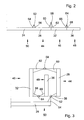
- eine Frontansicht der linken Hälfte des Erntevorsatzes in der Arbeitsstellung, und
- Fig. 3
- eine Frontansicht der linken Hälfte des Erntevorsatzes in der Transportstellung.
- Fig. 1
- a top view of a self-propelled harvester with a header arranged thereon,
- Fig. 2
- a front view of the left half of the header in the working position, and
- Fig. 3
- a front view of the left half of the header in the transport position.
In der
Der Erntevorsatz 14 umfasst einen Tragrahmen, der einen Mittelabschnitt 24 und zwei daran an beiden seitlichen Enden angeordnete, erste seitliche Abschnitte 26, 28 umfasst, an deren seitlichen Enden sich zweite seitliche Abschnitte 30, 32 anschließen, und an deren seitlichen Enden sich äußere Abschnitte 34, 36 anschließen. Die ersten seitlichen Abschnitte 26, 28 des Tragrahmens tragen jeweils ein Mäh- und Förderelement 18, während der Mittelabschnitt 24 des Tragrahmens zwei Mäh- und Förderelemente 16 trägt und die zweiten seitlichen Abschnitte 30, 32 des Tragrahmens jeweils ein Mäh- und Förderelement 20 tragen und die äußeren Abschnitte 34, 36 des Tragrahmens auch je ein Mäh- und Förderelement 22 tragen.The
Das im Erntebetrieb von den in den gezeigten Pfeilrichtungen um die Hochachse rotierenden, durch einen Antriebsstrang von der Erntemaschine 10 her angetriebenen Mäh- und Förderelementen 16,18, 20, 22 vom Boden abgetrennte Erntematerial wird an ihren Rückseiten im Zusammenwirken mit an den ersten seitlichen Abschnitten 26, 28 des Tragrahmens angebrachten Querfördertrommeln 38 und an den zweiten seitlichen Abschnitten 30, 32 des Tragrahmens angebrachten Querfördertrommeln 40 und am Mittelabschnitt 24 angebrachten Schrägfördertrommeln 42 in den Einzugskanal 12 der Erntemaschine 10 gefördert, von der es gehäckselt und auf ein Transportfahrzeug ausgeworfen wird.The harvested material from the crop rotation in the arrow directions shown about the vertical axis, driven by a drive train from the
Der Mittelabschnitt 24 des Tragrahmens bildet mit den daran befestigten Mäh- und Förderelementen 16 und den zugehörigen Schrägfördertrommeln 42 einen Mittelteil 50 des Erntevorsatzes 14.The
Der in Vorwärtsrichtung der Erntemaschine 10 rechte erste seitliche Abschnitt 26 des Tragrahmens bildet mit den daran befestigten Mäh- und Förderelementen 18 und der zugehörigen Querfördertrommel 38 einen ersten Seitenteil 44 des Erntevorsatzes 14. Der in Vorwärtsrichtung der Erntemaschine 10 linke erste seitliche Abschnitt 28 des Tragrahmens bildet mit den daran befestigten Mäh- und Förderelementen 18 und der zugehörigen Querfördertrommel 38 einen weiteren ersten Seitenteil 44 des Erntevorsatzes 14.The right in the forward direction of the
Der in Vorwärtsrichtung der Erntemaschine 10 rechte zweite seitliche Abschnitt 30 des Tragrahmens bildet mit den daran befestigten Mäh- und Förderelementen 20 und der zugehörigen Querfördertrommel 40 einen zweiten Seitenteil 46 des Erntevorsatzes 14. Der in Vorwärtsrichtung der Erntemaschine 10 linke zweite seitliche Abschnitt 32 des Tragrahmens bildet mit den daran befestigten Mäh- und Förderelementen 20 und der zugehörigen Querfördertrommel 40 einen weiteren zweiten Seitenteil 46 des Erntevorsatzes 14.The right in the forward direction of the
Der in Vorwärtsrichtung der Erntemaschine 10 rechte äußere Abschnitt 34 des Tragrahmens bildet mit den daran befestigten Mäh- und Förderelementen 22 einen Außenteil 48 des Erntevorsatzes 14.The right in the forward direction of the
Der in Vorwärtsrichtung der Erntemaschine 10 linke äußere Abschnitt 36 des Tragrahmens bildet mit den daran befestigten Mäh- und Förderelementen 22 einen weiteren Außenteil 48 des Erntevorsatzes 14.The left in the forward direction of the
In der in den
Die ersten seitlichen Abschnitte 26, 28 der ersten Seitenteile 44 sind jeweils um eine sich horizontal und in Vorwärtsrichtung erstreckende erste Achse 52 schwenkbar am Mittelabschnitt 24 des Mittelteils 50 angelenkt, die durch Halterungen 54, 56 mit dem Mittelabschnitt 24 bzw. dem ersten seitlichen Abschnitt 26, 28 verbunden sind. Die zweiten seitlichen Abschnitte 30, 32 der zweiten Seitenteile 46 sind jeweils um eine sich horizontal und in Vorwärtsrichtung erstreckende zweite Achse 58 schwenkbar am benachbarten Ende des ersten seitlichen Abschnitts 26 oder 28 angelenkt, die durch Halterungen 60, 62 mit dem ersten Abschnitt 26 oder 28 bzw. dem zweiten seitlichen Abschnitt 30, 32 verbunden sind. Die äußeren Abschnitte 36, 38 der Außenteile 48 sind jeweils um eine sich horizontal und in Vorwärtsrichtung erstreckende dritte Achse 64 schwenkbar am benachbarten Ende des zweiten seitlichen Abschnitts 30 oder 32 angelenkt, die durch Halterungen 66, 68 mit dem zweiten Abschnitt 30 oder 32 bzw. dem äußeren Abschnitt 36, 38 verbunden sind. Die zweite Achse 58 ist weiter von den Abschnitten 28, 32 (bzw. 26 und 30) entfernt als die Achsen 52 und 64 von den ihnen benachbarten Abschnitten, damit in der Transportstellung der Außenteil 48 zwischen den Seitenteilen 44, 46 Platz findet.The
Die Achsen 52, 58, 64 sind zweckmäßigerweise als Scharniere ausgeführt. Fremdkraftbetätigte Aktoren (nicht gezeigt) dienen in an sich bekannter Weise zum Verschwenken der Abschnitte 26 bis 36 um die Achsen 52, 58, 64. Die Aktoren können Rotationsantriebe sein, z. B. Hydraulikmotore, oder Linearantriebe, z. B. Hydraulikzylinder, die über geeignete Antriebsstränge mit den Abschnitten 26 bis 36 verbunden sind, wie Seilzüge oder an sich bekannte Gestänge (s.
Die Aktoren verschwenken die Außenteile 48 um 180° gegenüber den zweiten Seitenteilen 46 um die dritten Achsen 64 nach innen. Anschließend oder gleichzeitig werden die zweiten Seitenteile 46 um die zweiten Achsen 58 gegenüber den ersten Seitenteilen 44 um 180° um die Achsen 58 nach innen verschwenkt. Anschließend oder gleichzeitig werden die ersten Seitenteile 44 um die ersten Achsen 52 gegenüber dem Mittelteil 50 um 90° um die Achsen 52 nach oben verschwenkt. Die Kontrolle der Reihenfolge der Schwenkbewegungen kann auf einer Erfassung der Position der Aktoren oder der Seitenteile 44, 46 und des Außenteils 48 oder auf einer Zeiterfassung basieren oder mittels einer geeigneten Reihenschaltung der Aktoren erfolgen (s.
Claims (6)
- Harvester head (14) for agricultural harvesting machines (10) to gather and transport cereals, for example maize, which harvester head is moveable over a field in a forwards direction during the harvesting mode, with a central part (50) which can be attached to a harvesting machine (10), two first side parts (44) which are each articulated on a different side of the central part (50) in a manner such that they can pivot about a first axis (52), which extends horizontally and in the forwards direction, between a working position and a transport position, and two second side parts (46) which are each articulated on the outside of one of the first side parts (44) in a manner such that they can pivot about a second axis (58), which extends horizontally and in the forwards direction, between a working position and a transport position, wherein the central part (50) and the first and second side parts (44, 46) comprise mowing and conveying elements (16, 18, 20) arranged laterally next to one another in the working position, and the side parts (44, 46) of each side of the harvester head (14) can be pivoted in the opposite or same direction about the associated axes (52, 58) between the working position and the transport position, in which said side parts are located above the central part (50), characterized in that an outer part (48) comprising mowing and conveying elements (22) is in each case articulated on the outside of the second side parts (46) in a manner such that it can be pivoted about a third axis (64), which extends horizontally and in the forwards direction, between a working position and a transport position, and in that the outer parts (48) are oriented vertically in the transport position and are located between the vertically oriented side parts (44, 46).
- Harvester head (14) according to Claim 1, characterized in that the outer parts (48) can be pivoted in the same direction or opposite direction with the side parts (44, 46) of the respective side of the harvester head (14) between the working position and the transport position.
- Harvester head (14) according to Claim 1 or 2, characterized in that the first side parts (44) can be pivoted between the working position and the transport position by 90° about the first axis (52) in relation to the central part (50).
- Harvest head (14) according to one of Claims 1 to 3, characterized in that the second side parts (46) can be pivoted between the working position and the transport position by 180° about the second axis (58) in relation to the first side parts (44).
- Harvester head (14) according to one of Claims 1 to 4, characterized in that the outer parts (48) can be pivoted between the working position and the transport position by 180° about the third axis (64) in relation to the second side parts (46).
- Harvester head (14) according to one of Claims 1 to 5, characterized in that the second axis (58) is further away from sections (26 to 36) of a supporting frame of the first and second side parts (44, 46) than the first axis (52) is from a section (24) of a supporting frame of the central part (50) and from sections (26, 28) of the supporting frame of the first side parts (44), and in that the second axis (58) is further away from sections (26 to 36) of a supporting frame of the first and second side parts (44, 46) than the third axis (64) is from sections (26 to 36) of a supporting frame of the outer parts (48) and of the second side parts (46).
Applications Claiming Priority (1)
| Application Number | Priority Date | Filing Date | Title |
|---|---|---|---|
| DE102007058312A DE102007058312A1 (en) | 2007-12-04 | 2007-12-04 | Harvest header for agricultural harvesters for picking up and passing on strawberries |
Publications (2)
| Publication Number | Publication Date |
|---|---|
| EP2067397A1 EP2067397A1 (en) | 2009-06-10 |
| EP2067397B1 true EP2067397B1 (en) | 2011-06-22 |
Family
ID=40418051
Family Applications (1)
| Application Number | Title | Priority Date | Filing Date |
|---|---|---|---|
| EP08168993A Active EP2067397B1 (en) | 2007-12-04 | 2008-11-13 | Harvester head to gather and transport cereals in an agricultural harvesting machine |
Country Status (3)
| Country | Link |
|---|---|
| EP (1) | EP2067397B1 (en) |
| AT (1) | ATE513463T1 (en) |
| DE (1) | DE102007058312A1 (en) |
Families Citing this family (12)
| Publication number | Priority date | Publication date | Assignee | Title |
|---|---|---|---|---|
| DE102010002878A1 (en) * | 2010-03-15 | 2011-09-15 | Maschinenfabrik Kemper Gmbh & Co. Kg | Movable header between operating and transport position |
| DK3045029T3 (en) * | 2013-05-03 | 2018-06-06 | De Sluis Jacky Van | Combination lawn mower with wheel mower cutting units |
| US11395459B2 (en) | 2013-05-03 | 2022-07-26 | Jacky Van De Sluis | Gang mower with reel mower cutting units carried by two V-shaped beams foldable on a trailer frame |
| DE102014013141B4 (en) * | 2014-09-10 | 2023-03-09 | Claas Saulgau Gmbh | Agricultural implement |
| DE102015206142A1 (en) | 2015-04-07 | 2016-10-13 | Maschinenfabrik Kemper Gmbh & Co. Kg | Harvest header for agricultural harvesters |
| DE102015206343B4 (en) | 2015-04-09 | 2024-08-22 | Maschinenfabrik Kemper Gmbh & Co. Kg | Harvester with telescopic mower drum attachment |
| DE102015206346A1 (en) | 2015-04-09 | 2016-10-13 | Maschinenfabrik Kemper Gmbh & Co. Kg | Harvest header for agricultural harvesters for picking up and passing on strawberries |
| US10070575B2 (en) | 2016-08-05 | 2018-09-11 | Cnh Industrial America Llc | Agricultural machine with folding header |
| US10433483B2 (en) | 2017-08-21 | 2019-10-08 | Cnh Industrial America Llc | Agricultural header with one or more movable wing sections |
| NL1044084B1 (en) | 2021-07-05 | 2023-01-11 | Evers Agro B V | MANURE INJECTOR |
| DE102022128070A1 (en) * | 2022-10-24 | 2024-04-25 | Claas Saulgau Gmbh | Maize header for a forage harvester and forage harvesters with such a maize header |
| DE102022128071A1 (en) * | 2022-10-24 | 2024-04-25 | Claas Saulgau Gmbh | Maize header for a forage harvester and forage harvesters with such a maize header |
Family Cites Families (10)
| Publication number | Priority date | Publication date | Assignee | Title |
|---|---|---|---|---|
| US4133391A (en) * | 1976-08-24 | 1979-01-09 | Richardson Manufacturing Company, Inc. | Folding flexible undercutter plow |
| US4355690A (en) | 1980-12-18 | 1982-10-26 | Deere & Company | Stack folding outrigger system |
| DE3324458A1 (en) | 1983-07-07 | 1985-01-24 | Carl Geringhoff GmbH & Co KG, 4730 Ahlen | MAISER MACHINE |
| IT1241605B (en) | 1990-12-18 | 1994-01-19 | Capello R & F Flli | FOLDABLE HEADBOARD FOR THE COLLECTION OF CORN |
| DE4131491C2 (en) | 1991-09-21 | 1999-11-18 | Claas Saulgau Gmbh | Corn harvester for forage harvesters |
| DE19800356A1 (en) * | 1998-01-08 | 1999-07-15 | Poettinger Gmbh Geb | Rotary tedder for agricultural tractors |
| DE19823555A1 (en) * | 1998-05-27 | 1999-12-02 | Claas Saulgau Gmbh | Haymaking machine |
| DE29817666U1 (en) | 1998-10-05 | 1998-12-10 | Maschinenfabrik Kemper GmbH & Co. KG, 48703 Stadtlohn | Maize cutting machine and the like stem-like crop |
| DE10303380A1 (en) | 2003-01-29 | 2004-08-05 | Claas Saulgau Gmbh | Agricultural harvester, comprising front attachment to be swiveled into particularly safe position for transport |
| US7497269B2 (en) * | 2005-10-07 | 2009-03-03 | Bourgault Industries Ltd. | Folding transport system with wing lock for an implement |
-
2007
- 2007-12-04 DE DE102007058312A patent/DE102007058312A1/en not_active Withdrawn
-
2008
- 2008-11-13 AT AT08168993T patent/ATE513463T1/en active
- 2008-11-13 EP EP08168993A patent/EP2067397B1/en active Active
Also Published As
| Publication number | Publication date |
|---|---|
| ATE513463T1 (en) | 2011-07-15 |
| DE102007058312A1 (en) | 2009-06-10 |
| EP2067397A1 (en) | 2009-06-10 |
Similar Documents
| Publication | Publication Date | Title |
|---|---|---|
| EP2067397B1 (en) | Harvester head to gather and transport cereals in an agricultural harvesting machine | |
| EP1709858B1 (en) | Harvester head for agricultural machines | |
| EP1287732B1 (en) | Harvester head | |
| EP1362504A1 (en) | Machine for mowing stalk crops | |
| EP1095555B1 (en) | Haymaking machine | |
| DE102008042392B4 (en) | Harvesting header for agricultural harvesting machines | |
| EP1093708A1 (en) | Mowing device | |
| DE102007002659A1 (en) | Machine for mowing stalk-like crops | |
| EP1796454B1 (en) | Harvesting equipment, in particular harvesting attachment for agricultural harvesting machines used to gather and transport cereals | |
| DE102005006216B4 (en) | Self-propelled agricultural harvester | |
| DE102008058281A1 (en) | Mower and method for creating ravages when mowing a field | |
| EP2055174B1 (en) | Self-propelled agricultural harvester | |
| DE102005004212B4 (en) | Harvest header for agricultural harvester | |
| DE102006030508B4 (en) | Arrangement for pendulum suspension of a header on a harvester | |
| DE102015206142A1 (en) | Harvest header for agricultural harvesters | |
| BE1031908B1 (en) | Harvesting header for a self-propelled harvester | |
| DE102006053771B4 (en) | Machine for mowing stalk-like crops | |
| EP2735220B1 (en) | Harvesting header movable between an operational and a transport position | |
| DE102014208071B4 (en) | Between an operating and a transport position adjustable agricultural implement | |
| DE102013208349B4 (en) | Drive arrangement for a header of a harvesting machine | |
| DE102007059267A1 (en) | Harvesting attachment for agricultural harvesting machines used to gather and transport cereals, has central part attached at harvesting machine, two side frames and two outer frames | |
| EP1922915B1 (en) | Machine for mowing stalk-like crops | |
| DE102006047530A1 (en) | Harvesting equipment for use with e.g. forage harvester, has conveyer device adjustable between harvesting and transportation positions, in which distance between conveyor units is reduced among each other in relation to harvesting position | |
| DE102012221278B4 (en) | Movable harvesting attachment between operating and transport position with asymmetrical middle and outer parts | |
| DE102006022480B4 (en) | Agricultural implement with a support frame |
Legal Events
| Date | Code | Title | Description |
|---|---|---|---|
| PUAI | Public reference made under article 153(3) epc to a published international application that has entered the european phase |
Free format text: ORIGINAL CODE: 0009012 |
|
| AK | Designated contracting states |
Kind code of ref document: A1 Designated state(s): AT BE BG CH CY CZ DE DK EE ES FI FR GB GR HR HU IE IS IT LI LT LU LV MC MT NL NO PL PT RO SE SI SK TR |
|
| AX | Request for extension of the european patent |
Extension state: AL BA MK RS |
|
| 17P | Request for examination filed |
Effective date: 20091210 |
|
| 17Q | First examination report despatched |
Effective date: 20100119 |
|
| AKX | Designation fees paid |
Designated state(s): AT BE BG CH CY CZ DE DK EE ES FI FR GB GR HR HU IE IS IT LI LT LU LV MC MT NL NO PL PT RO SE SI SK TR |
|
| GRAP | Despatch of communication of intention to grant a patent |
Free format text: ORIGINAL CODE: EPIDOSNIGR1 |
|
| GRAS | Grant fee paid |
Free format text: ORIGINAL CODE: EPIDOSNIGR3 |
|
| GRAA | (expected) grant |
Free format text: ORIGINAL CODE: 0009210 |
|
| AK | Designated contracting states |
Kind code of ref document: B1 Designated state(s): AT BE BG CH CY CZ DE DK EE ES FI FR GB GR HR HU IE IS IT LI LT LU LV MC MT NL NO PL PT RO SE SI SK TR |
|
| REG | Reference to a national code |
Ref country code: GB Ref legal event code: FG4D Free format text: NOT ENGLISH |
|
| REG | Reference to a national code |
Ref country code: CH Ref legal event code: EP |
|
| REG | Reference to a national code |
Ref country code: IE Ref legal event code: FG4D Free format text: LANGUAGE OF EP DOCUMENT: GERMAN |
|
| REG | Reference to a national code |
Ref country code: DE Ref legal event code: R096 Ref document number: 502008003944 Country of ref document: DE Effective date: 20110804 |
|
| REG | Reference to a national code |
Ref country code: NL Ref legal event code: VDEP Effective date: 20110622 |
|
| PG25 | Lapsed in a contracting state [announced via postgrant information from national office to epo] |
Ref country code: LT Free format text: LAPSE BECAUSE OF FAILURE TO SUBMIT A TRANSLATION OF THE DESCRIPTION OR TO PAY THE FEE WITHIN THE PRESCRIBED TIME-LIMIT Effective date: 20110622 Ref country code: NO Free format text: LAPSE BECAUSE OF FAILURE TO SUBMIT A TRANSLATION OF THE DESCRIPTION OR TO PAY THE FEE WITHIN THE PRESCRIBED TIME-LIMIT Effective date: 20110922 Ref country code: SE Free format text: LAPSE BECAUSE OF FAILURE TO SUBMIT A TRANSLATION OF THE DESCRIPTION OR TO PAY THE FEE WITHIN THE PRESCRIBED TIME-LIMIT Effective date: 20110622 Ref country code: HR Free format text: LAPSE BECAUSE OF FAILURE TO SUBMIT A TRANSLATION OF THE DESCRIPTION OR TO PAY THE FEE WITHIN THE PRESCRIBED TIME-LIMIT Effective date: 20110622 |
|
| PG25 | Lapsed in a contracting state [announced via postgrant information from national office to epo] |
Ref country code: GR Free format text: LAPSE BECAUSE OF FAILURE TO SUBMIT A TRANSLATION OF THE DESCRIPTION OR TO PAY THE FEE WITHIN THE PRESCRIBED TIME-LIMIT Effective date: 20110923 Ref country code: LV Free format text: LAPSE BECAUSE OF FAILURE TO SUBMIT A TRANSLATION OF THE DESCRIPTION OR TO PAY THE FEE WITHIN THE PRESCRIBED TIME-LIMIT Effective date: 20110622 Ref country code: SI Free format text: LAPSE BECAUSE OF FAILURE TO SUBMIT A TRANSLATION OF THE DESCRIPTION OR TO PAY THE FEE WITHIN THE PRESCRIBED TIME-LIMIT Effective date: 20110622 Ref country code: CY Free format text: LAPSE BECAUSE OF FAILURE TO SUBMIT A TRANSLATION OF THE DESCRIPTION OR TO PAY THE FEE WITHIN THE PRESCRIBED TIME-LIMIT Effective date: 20110622 Ref country code: FI Free format text: LAPSE BECAUSE OF FAILURE TO SUBMIT A TRANSLATION OF THE DESCRIPTION OR TO PAY THE FEE WITHIN THE PRESCRIBED TIME-LIMIT Effective date: 20110622 |
|
| PG25 | Lapsed in a contracting state [announced via postgrant information from national office to epo] |
Ref country code: NL Free format text: LAPSE BECAUSE OF FAILURE TO SUBMIT A TRANSLATION OF THE DESCRIPTION OR TO PAY THE FEE WITHIN THE PRESCRIBED TIME-LIMIT Effective date: 20110622 |
|
| REG | Reference to a national code |
Ref country code: IE Ref legal event code: FD4D |
|
| PG25 | Lapsed in a contracting state [announced via postgrant information from national office to epo] |
Ref country code: PT Free format text: LAPSE BECAUSE OF FAILURE TO SUBMIT A TRANSLATION OF THE DESCRIPTION OR TO PAY THE FEE WITHIN THE PRESCRIBED TIME-LIMIT Effective date: 20111024 Ref country code: IS Free format text: LAPSE BECAUSE OF FAILURE TO SUBMIT A TRANSLATION OF THE DESCRIPTION OR TO PAY THE FEE WITHIN THE PRESCRIBED TIME-LIMIT Effective date: 20111022 Ref country code: IE Free format text: LAPSE BECAUSE OF FAILURE TO SUBMIT A TRANSLATION OF THE DESCRIPTION OR TO PAY THE FEE WITHIN THE PRESCRIBED TIME-LIMIT Effective date: 20110622 Ref country code: CZ Free format text: LAPSE BECAUSE OF FAILURE TO SUBMIT A TRANSLATION OF THE DESCRIPTION OR TO PAY THE FEE WITHIN THE PRESCRIBED TIME-LIMIT Effective date: 20110622 Ref country code: EE Free format text: LAPSE BECAUSE OF FAILURE TO SUBMIT A TRANSLATION OF THE DESCRIPTION OR TO PAY THE FEE WITHIN THE PRESCRIBED TIME-LIMIT Effective date: 20110622 |
|
| PG25 | Lapsed in a contracting state [announced via postgrant information from national office to epo] |
Ref country code: SK Free format text: LAPSE BECAUSE OF FAILURE TO SUBMIT A TRANSLATION OF THE DESCRIPTION OR TO PAY THE FEE WITHIN THE PRESCRIBED TIME-LIMIT Effective date: 20110622 Ref country code: PL Free format text: LAPSE BECAUSE OF FAILURE TO SUBMIT A TRANSLATION OF THE DESCRIPTION OR TO PAY THE FEE WITHIN THE PRESCRIBED TIME-LIMIT Effective date: 20110622 Ref country code: RO Free format text: LAPSE BECAUSE OF FAILURE TO SUBMIT A TRANSLATION OF THE DESCRIPTION OR TO PAY THE FEE WITHIN THE PRESCRIBED TIME-LIMIT Effective date: 20110622 |
|
| PLBE | No opposition filed within time limit |
Free format text: ORIGINAL CODE: 0009261 |
|
| STAA | Information on the status of an ep patent application or granted ep patent |
Free format text: STATUS: NO OPPOSITION FILED WITHIN TIME LIMIT |
|
| 26N | No opposition filed |
Effective date: 20120323 |
|
| PG25 | Lapsed in a contracting state [announced via postgrant information from national office to epo] |
Ref country code: IT Free format text: LAPSE BECAUSE OF FAILURE TO SUBMIT A TRANSLATION OF THE DESCRIPTION OR TO PAY THE FEE WITHIN THE PRESCRIBED TIME-LIMIT Effective date: 20110622 |
|
| PG25 | Lapsed in a contracting state [announced via postgrant information from national office to epo] |
Ref country code: DK Free format text: LAPSE BECAUSE OF FAILURE TO SUBMIT A TRANSLATION OF THE DESCRIPTION OR TO PAY THE FEE WITHIN THE PRESCRIBED TIME-LIMIT Effective date: 20110622 Ref country code: MC Free format text: LAPSE BECAUSE OF NON-PAYMENT OF DUE FEES Effective date: 20111130 |
|
| REG | Reference to a national code |
Ref country code: DE Ref legal event code: R097 Ref document number: 502008003944 Country of ref document: DE Effective date: 20120323 |
|
| REG | Reference to a national code |
Ref country code: FR Ref legal event code: ST Effective date: 20120731 |
|
| PG25 | Lapsed in a contracting state [announced via postgrant information from national office to epo] |
Ref country code: FR Free format text: LAPSE BECAUSE OF NON-PAYMENT OF DUE FEES Effective date: 20111130 |
|
| PG25 | Lapsed in a contracting state [announced via postgrant information from national office to epo] |
Ref country code: MT Free format text: LAPSE BECAUSE OF FAILURE TO SUBMIT A TRANSLATION OF THE DESCRIPTION OR TO PAY THE FEE WITHIN THE PRESCRIBED TIME-LIMIT Effective date: 20110622 |
|
| PG25 | Lapsed in a contracting state [announced via postgrant information from national office to epo] |
Ref country code: ES Free format text: LAPSE BECAUSE OF FAILURE TO SUBMIT A TRANSLATION OF THE DESCRIPTION OR TO PAY THE FEE WITHIN THE PRESCRIBED TIME-LIMIT Effective date: 20111003 |
|
| PG25 | Lapsed in a contracting state [announced via postgrant information from national office to epo] |
Ref country code: LU Free format text: LAPSE BECAUSE OF NON-PAYMENT OF DUE FEES Effective date: 20111113 |
|
| PG25 | Lapsed in a contracting state [announced via postgrant information from national office to epo] |
Ref country code: BG Free format text: LAPSE BECAUSE OF FAILURE TO SUBMIT A TRANSLATION OF THE DESCRIPTION OR TO PAY THE FEE WITHIN THE PRESCRIBED TIME-LIMIT Effective date: 20110922 |
|
| REG | Reference to a national code |
Ref country code: CH Ref legal event code: PL |
|
| GBPC | Gb: european patent ceased through non-payment of renewal fee |
Effective date: 20121113 |
|
| PG25 | Lapsed in a contracting state [announced via postgrant information from national office to epo] |
Ref country code: CH Free format text: LAPSE BECAUSE OF NON-PAYMENT OF DUE FEES Effective date: 20121130 Ref country code: LI Free format text: LAPSE BECAUSE OF NON-PAYMENT OF DUE FEES Effective date: 20121130 |
|
| PG25 | Lapsed in a contracting state [announced via postgrant information from national office to epo] |
Ref country code: TR Free format text: LAPSE BECAUSE OF FAILURE TO SUBMIT A TRANSLATION OF THE DESCRIPTION OR TO PAY THE FEE WITHIN THE PRESCRIBED TIME-LIMIT Effective date: 20110622 |
|
| PG25 | Lapsed in a contracting state [announced via postgrant information from national office to epo] |
Ref country code: HU Free format text: LAPSE BECAUSE OF FAILURE TO SUBMIT A TRANSLATION OF THE DESCRIPTION OR TO PAY THE FEE WITHIN THE PRESCRIBED TIME-LIMIT Effective date: 20110622 |
|
| PG25 | Lapsed in a contracting state [announced via postgrant information from national office to epo] |
Ref country code: GB Free format text: LAPSE BECAUSE OF NON-PAYMENT OF DUE FEES Effective date: 20121113 |
|
| REG | Reference to a national code |
Ref country code: AT Ref legal event code: MM01 Ref document number: 513463 Country of ref document: AT Kind code of ref document: T Effective date: 20131113 |
|
| PG25 | Lapsed in a contracting state [announced via postgrant information from national office to epo] |
Ref country code: AT Free format text: LAPSE BECAUSE OF NON-PAYMENT OF DUE FEES Effective date: 20131113 |
|
| PGFP | Annual fee paid to national office [announced via postgrant information from national office to epo] |
Ref country code: DE Payment date: 20251021 Year of fee payment: 18 |
|
| PGFP | Annual fee paid to national office [announced via postgrant information from national office to epo] |
Ref country code: BE Payment date: 20251127 Year of fee payment: 18 |