EP2067397B1 - Tête de récolte servant à cueillir et transporter des céréales pour une récolteuse agricole - Google Patents
Tête de récolte servant à cueillir et transporter des céréales pour une récolteuse agricole Download PDFInfo
- Publication number
- EP2067397B1 EP2067397B1 EP08168993A EP08168993A EP2067397B1 EP 2067397 B1 EP2067397 B1 EP 2067397B1 EP 08168993 A EP08168993 A EP 08168993A EP 08168993 A EP08168993 A EP 08168993A EP 2067397 B1 EP2067397 B1 EP 2067397B1
- Authority
- EP
- European Patent Office
- Prior art keywords
- side parts
- axis
- parts
- pivoted
- transport position
- Prior art date
- Legal status (The legal status is an assumption and is not a legal conclusion. Google has not performed a legal analysis and makes no representation as to the accuracy of the status listed.)
- Active
Links
- 238000003306 harvesting Methods 0.000 title claims description 16
- 235000013339 cereals Nutrition 0.000 title claims 2
- 240000008042 Zea mays Species 0.000 claims description 6
- 235000002017 Zea mays subsp mays Nutrition 0.000 claims description 6
- 235000016383 Zea mays subsp huehuetenangensis Nutrition 0.000 claims description 3
- 235000009973 maize Nutrition 0.000 claims description 3
- 241000196324 Embryophyta Species 0.000 description 3
- 241001124569 Lycaenidae Species 0.000 description 3
- 235000005824 Zea mays ssp. parviglumis Nutrition 0.000 description 3
- 235000005822 corn Nutrition 0.000 description 3
- 239000004459 forage Substances 0.000 description 3
- 244000025254 Cannabis sativa Species 0.000 description 1
- 241001057636 Dracaena deremensis Species 0.000 description 1
- 240000009088 Fragaria x ananassa Species 0.000 description 1
- 238000003967 crop rotation Methods 0.000 description 1
- 238000001514 detection method Methods 0.000 description 1
- 239000000463 material Substances 0.000 description 1
- 235000021012 strawberries Nutrition 0.000 description 1
Images

Classifications
-
- A—HUMAN NECESSITIES
- A01—AGRICULTURE; FORESTRY; ANIMAL HUSBANDRY; HUNTING; TRAPPING; FISHING
- A01D—HARVESTING; MOWING
- A01D41/00—Combines, i.e. harvesters or mowers combined with threshing devices
- A01D41/12—Details of combines
- A01D41/14—Mowing tables
- A01D41/144—Foldable headers
-
- A—HUMAN NECESSITIES
- A01—AGRICULTURE; FORESTRY; ANIMAL HUSBANDRY; HUNTING; TRAPPING; FISHING
- A01B—SOIL WORKING IN AGRICULTURE OR FORESTRY; PARTS, DETAILS, OR ACCESSORIES OF AGRICULTURAL MACHINES OR IMPLEMENTS, IN GENERAL
- A01B73/00—Means or arrangements to facilitate transportation of agricultural machines or implements, e.g. folding frames to reduce overall width
- A01B73/02—Folding frames
- A01B73/04—Folding frames foldable about a horizontal axis
- A01B73/044—Folding frames foldable about a horizontal axis the axis being oriented in a longitudinal direction
- A01B73/046—Folding frames foldable about a horizontal axis the axis being oriented in a longitudinal direction each folding frame part being foldable in itself
Definitions
- the invention relates to a harvesting attachment for agricultural harvesting machines for receiving and conveying strawberries, for example corn plants, which is movable in a forward direction over a field during harvesting operation, with an attachable to a harvester central part, two first side parts, each on a different side of the middle part about a first, horizontally and in the forward direction extending axis between a working position and a transport position pivotally articulated, and two second side parts, each on the outside at one of the first side parts about a second, horizontally and in the forward direction extending axis between a working position and a transport position are pivotally articulated, wherein the middle part and the first and second side parts in the working position laterally juxtaposed mowing and conveying elements comprise and the side parts of each side of the header g ege- or in the same direction about the associated axes between the working position and the transport position are pivotable, in which they are located above the middle part.
- DE 41 31 491 A describes a maize harvester for forage harvesters, in which the outer parts can be folded up about horizontal, in the forward direction axes.
- the side parts are pivoted about horizontal, in the forward direction axes and placed horizontally over the middle part, while in the considered as generic DE 298 17 666 U is proposed to pivot in a five-piece header, the inner side panels in the transport position vertically upwards and turn the outer side panels in contrast again inwardly in an approximately horizontal position, so that the outer side parts are arranged above the middle parts.
- the DE 103 03 380 A describes another five-piece header, in which the inner side parts are pivoted in the transport position by about 135 ° upwards and inwards, while the outer side parts are pivoted in opposite directions to the inner side parts by 180 ° to the outside.
- the working width of the header is limited by the maximum permissible height during road travel when the side parts are pivoted upwards by 90 ° ( DE 41 31 491 A ), or it is limited to twice the width permitted on the road when the side parts are pivoted inwards by 180 ° and deposited above the middle part ( EP 0 491 405 A ).
- the arrangement after DE 298 17 666 U allows larger working widths, which are also limited by height and width restrictions in road travel upwards, which also for the embodiment according to DE 103 03 380 A applies.
- the object underlying the invention is seen to provide a harvesting attachment, which allows a greater working width compared to the prior art in compliance with restrictions on the transport width and height.
- a harvesting header comprises a central part and at its lateral ends pivotally hinged about first horizontal and forward axes extending first side panels. At the outer ends of the first side parts second side parts are pivotally articulated about horizontally and in the forward direction extending second axes. At the outer ends of the second side parts in turn outer parts are hinged to horizontally and in the forward direction extending third axis.
- the central part is removably attachable to a harvester, be it rigid or a horizontal, extending in the forward direction swing axle to adjust the position of the header to ground contours, the pendulum motion is suppressed when driving on the road.
- the header therefore comprises a total of (at least) seven parts, namely the middle part, four side parts and two outer parts.
- All these parts include mowing and conveying elements for receiving and conveying plants and extend in a working position transversely to the forward direction and horizontally in a common working plane.
- the outer and side parts are pivoted about the axes mentioned in a transport position, including power-operated actuators, in particular in the form of hydraulic cylinders, are provided.
- the side parts are pivoted inwards or inwards in the same direction.
- the outer parts are also pivoted relative to the second side parts about third axes in their transport position, it being possible to pivot them in the same direction with the side parts of the associated side inwards, or in opposite directions to rotate outwards.
- the second side parts are pivoted in the transport position by 180 ° about the second axis inwardly, while the outer parts are pivoted in the transport position by 180 ° about the third axis inwardly.
- the side parts and the outer parts in the transport position take a sandwich-like configuration in which they are all oriented vertically and the outer part is located between the two side parts.
- the first side parts are furthest out and the second side parts furthest inside.
- the individual parts can be pivoted one after the other at the same time or in a suitable order avoiding a collision.
- the invention is suitable for all types of harvesting attachments, such as maize headers, corn pickers and cutting units, which can be used on self-propelled or tractor-mounted harvesting machines, especially in the form of mounted or towed or self-propelled forage harvester or combine harvesters.
- a promotion of the crop in the harvester is not mandatory, so that the invention, for example, to carrier vehicles with mowers in the form of mowing or mowing or the like. Can be used for cutting grass with pivoting side and outer parts application.
- the first side parts are oriented vertically in the transport position, d. H. They are pivoted 90 ° between the working position and the transport position.
- the second side parts are pivoted by 180 ° inwards, so that they are then oriented vertically downwards.
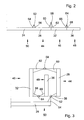
- FIG. 1 is a plan view of a self-propelled harvester 10 in the form of a forage harvester reproduced with a on the intake duct 12 of the harvester 10 releasably mounted header 14.
- the harvesting attachment 14 exemplified here as an embodiment of a harvesting device is designed in the form of a mowing attachment and comprises eight juxtaposed mowing and conveying elements 16, 18, 20, 22 for cutting and pulling stalk-like crops, such as corn, which operate independently of rows and from lower Cutting discs and upper conveyor drums with superimposed conveyor discs composed around their edge recesses for receiving plants that rotate about common, vertical axes.
- any other numbers and embodiments of mowing and conveying elements 16, 18, 20, 22 could also be used, in particular with endless conveyors.
- the working widths of the individual mowing and conveying elements 16, 18, 20, 22 amount in the illustrated embodiment in each case 1.5 m (corresponding to two rows of cultivated at a distance of 75 cm plants, such as corn), so that the total working width is 12 m.
- the working widths of the individual mowing and conveying elements 16, 18, 20, 22 can also be smaller or larger than mentioned and also different.
- the working width of the outer mowing and conveying elements could be only 75 cm.
- the header 14 comprises a support frame comprising a central portion 24 and two first side portions 26, 28 disposed thereon at both lateral ends, at the lateral ends of which second lateral portions 30, 32 adjoin, and outer portions 34 at the lateral ends thereof , 36 connect.
- the first lateral sections 26, 28 of the support frame each carry a mowing and conveying element 18, while the central portion 24 of the support frame two mowing and Conveyor elements 16 carries and the second lateral portions 30, 32 of the support frame each carry a mowing and conveying element 20 and the outer portions 34, 36 of the support frame also each carry a mowing and conveying element 22.
- the harvested material from the crop rotation in the arrow directions shown about the vertical axis, driven by a drive train from the harvester 10 ago mowing and conveying elements 16,18, 20, 22 separated from the ground crop is at its rear sides in cooperation with at the first lateral sections 26, 28 of the support frame mounted transverse conveyor drums 38 and attached to the second side sections 30, 32 of the support frame transverse conveyor drums 40 and attached to the central portion 24 inclined conveyor drums 42 fed into the intake duct 12 of the harvester 10, from which it is chopped and ejected onto a transport vehicle.
- the central portion 24 of the support frame forms with the attached mowing and conveying elements 16 and the associated inclined conveyor drums 42 a central portion 50 of the header 14th
- first lateral portion 26 of the support frame forms with the attached mowing and conveying elements 18 and the associated transverse conveyor drum 38, a first side portion 44 of the header 14.
- the forward in the forward direction of the harvester 10 left first side portion 28 of the support frame forms with the attached mowing and conveying elements 18 and the associated transverse conveyor drum 38, a further first side part 44 of the header 14th
- the right in the forward direction of the harvester 10 second lateral portion 30 of the support frame forms with the attached mowing and conveying elements 20 and the associated transverse conveyor drum 40, a second side portion 46 of the header 14.
- the forward in the forward direction of the harvester 10 second lateral portion 32 of the support frame forms with the attached mowing and conveying elements 20 and the associated transverse conveyor drum 40 another second side portion 46 of the header 14th
- outer portion 34 of the support frame forms with the attached mowing and conveying elements 22 an outer part 48 of the header 14th
- the side parts 44, 46 and the outer parts 48 are therefore arranged in the forward direction in a plane laterally adjacent to the central part 50.
- the header 14 is in a in the FIG. 3 shown transported position.
- the position of the central part 50 relative to the intake channel 12 does not change in the transport position relative to the working position.
- the first side portions 26, 28 of the first side members 44 are each hinged about a horizontally and forwardly extending first axis 52 pivotally mounted to the central portion 24 of the central portion 50 by brackets 54, 56 with the central portion 24 and the first lateral portion 26th , 28 are connected.
- the second side portions 30, 32 of the second side members 46 are each hinged about a horizontally and forwardly extending second axis 58 pivotally adjacent to the adjacent end of the first side portion 26 or 28 by holders 60, 62 with the first portion 26 or 28 or the second lateral section 30, 32 are connected.
- the outer portions 36, 38 of the outer members 48 are each hinged about a horizontally and forwardly extending third axis 64 pivotally at the adjacent end of the second lateral portion 30 or 32, by mounts 66, 68 with the second portion 30 or 32 or the outer portion 36, 38 are connected.
- the second axis 58 is farther from the sections 28, 32 (or 26 and 30) than the axes 52 and 64 of the sections adjacent thereto, thus in the transport position of the outer part 48 between the side panels 44, 46 finds room.
- the axes 52, 58, 64 are expediently designed as hinges.
- Power-operated actuators (not shown) serve in a conventional manner for pivoting the sections 26 to 36 about the axes 52, 58, 64.
- the actuators may be rotary actuators, for. B. hydraulic motors, or linear drives, z. B. hydraulic cylinders, which are connected via suitable drive trains to the sections 26 to 36, such as cables or per se known linkage (s. DE 33 24 458 A and US 4,355,690 A the disclosures of which are incorporated by reference into the present documentation).
- the actuators pivot the outer parts 48 by 180 ° relative to the second side parts 46 about the third axis 64 inwardly. Subsequently or simultaneously, the second side parts 46 are pivoted about the second axis 58 with respect to the first side parts 44 by 180 ° about the axes 58 inwardly. Subsequently or simultaneously, the first side parts 44 are pivoted about the first axis 52 with respect to the central part 50 by 90 ° about the axes 52 upwards.
- the control of the order of the pivoting movements can be based on a detection of the position of the actuators or the side parts 44, 46 and the outer part 48 or on a time recording or by means of a suitable series connection of the actuators (s. DE 298 17 666 U ).
Landscapes
- Life Sciences & Earth Sciences (AREA)
- Environmental Sciences (AREA)
- Engineering & Computer Science (AREA)
- Mechanical Engineering (AREA)
- Soil Sciences (AREA)
- Harvester Elements (AREA)
- Agricultural Machines (AREA)
Claims (6)
- Tête de récolte (14) pour des récolteuses agricoles (10), servant à cueillir et à transporter des céréales, par exemple des plants de maïs, qui peut être déplacée en mode de récolte dans une direction d'avance sur un champ, avec une partie centrale (50) pouvant être montée sur une récolteuse (10), deux premières parties latérales (44), qui sont articulées à chaque fois sur un autre côté de la partie centrale (50), de manière à pouvoir pivoter autour d'un premier axe (52) s'étendant horizontalement et dans la direction d'avance entre une position de travail et une position de transport, et deux deuxièmes parties latérales (46) qui sont articulées à chaque fois du côté extérieur sur l'une des premières parties latérales (44), de manière à pouvoir pivoter autour d'un deuxième axe (58) s'étendant horizontalement et dans la direction d'avance entre une position de travail et une position de transport, la partie centrale (50) et les premières et deuxièmes parties latérales (44, 46) comprenant des éléments de fauchage et de transport (16, 18, 20) disposés les uns à côté des autres latéralement dans la position de travail, et les parties latérales (44, 46) de chaque côté de la tête de récolte (14) pouvant pivoter en sens inverse ou dans le même sens autour des axes associés (52, 58) entre la position de travail et la position de transport, dans laquelle elles se trouvent au-dessus de la partie centrale (50), caractérisée en ce que du côté extérieur sur les deuxièmes parties latérales (46) est à chaque fois articulée une partie extérieure (48) comprenant des éléments de fauchage et de transport (22), de manière à pouvoir pivoter autour d'un troisième axe (64) s'étendant horizontalement et dans la direction d'avance entre une position de travail et une position de transport, et en ce que les parties extérieures (48) sont orientées verticalement dans la position de transport et se trouvent entre les parties latérales orientées verticalement (44, 46).
- Tête de récolte (14) selon la revendication 1, caractérisée en ce que les parties extérieures (48) peuvent pivoter dans le même sens ou en sens inverse avec les parties latérales (44, 46) du côté respectif de la tête de récolte (14) entre la position de travail et la position de transport.
- Tête de récolte (14) selon la revendication 1 ou 2, caractérisée en ce que les premières parties latérales (44) peuvent pivoter entre la position de travail et la position de transport par rapport à la partie centrale (50) de 90° autour du premier axe (52).
- Tête de récolte (14) selon l'une quelconque des revendications 1 à 3, caractérisée en ce que les deuxièmes parties latérales (46) peuvent pivoter entre la position de travail et la position de transport par rapport aux premières parties latérales (44) de 180° autour du deuxième axe (58).
- Tête de récolte (14) selon l'une quelconque des revendications 1 à 4, caractérisée en ce que les parties extérieures (48) peuvent pivoter entre la position de travail et la position de transport par rapport aux deuxièmes parties latérales (46) de 180° autour du troisième axe (64).
- Tête de récolte (14) selon l'une quelconque des revendications 1 à 5, caractérisée en ce que le deuxième axe (58) est plus éloigné de portions (26 à 36) d'un châssis porteur des premières et deuxièmes parties latérales (44, 46) que le premier axe (52) d'une portion (24) d'un châssis porteur de la partie centrale (50) et de portions (26, 28) du châssis porteur des premières parties latérales (44), et en ce que le deuxième axe (58) est plus éloigné de portions (26 à 36) d'un châssis porteur des premières et deuxièmes parties latérales (44, 46) que le troisième axe (64) de portions (26 à 36) d'un châssis porteur des parties extérieures (48) et des deuxièmes parties latérales (46).
Applications Claiming Priority (1)
| Application Number | Priority Date | Filing Date | Title |
|---|---|---|---|
| DE102007058312A DE102007058312A1 (de) | 2007-12-04 | 2007-12-04 | Erntevorsatz für landwirtschaftliche Erntemaschinen zum Aufnehmen und Weiterfördern von Halmfrüchten |
Publications (2)
| Publication Number | Publication Date |
|---|---|
| EP2067397A1 EP2067397A1 (fr) | 2009-06-10 |
| EP2067397B1 true EP2067397B1 (fr) | 2011-06-22 |
Family
ID=40418051
Family Applications (1)
| Application Number | Title | Priority Date | Filing Date |
|---|---|---|---|
| EP08168993A Active EP2067397B1 (fr) | 2007-12-04 | 2008-11-13 | Tête de récolte servant à cueillir et transporter des céréales pour une récolteuse agricole |
Country Status (3)
| Country | Link |
|---|---|
| EP (1) | EP2067397B1 (fr) |
| AT (1) | ATE513463T1 (fr) |
| DE (1) | DE102007058312A1 (fr) |
Families Citing this family (12)
| Publication number | Priority date | Publication date | Assignee | Title |
|---|---|---|---|---|
| DE102010002878A1 (de) * | 2010-03-15 | 2011-09-15 | Maschinenfabrik Kemper Gmbh & Co. Kg | Zwischen Betriebs- und Transportstellung bewegbarer Erntevorsatz |
| US11395459B2 (en) | 2013-05-03 | 2022-07-26 | Jacky Van De Sluis | Gang mower with reel mower cutting units carried by two V-shaped beams foldable on a trailer frame |
| DK2798936T3 (en) * | 2013-05-03 | 2016-08-01 | De Sluis Jacky Van | Combination Mower wheeled rock-cutting devices |
| DE102014013141B4 (de) * | 2014-09-10 | 2023-03-09 | Claas Saulgau Gmbh | Landwirtschaftliches Arbeitsgerät |
| DE102015206142A1 (de) | 2015-04-07 | 2016-10-13 | Maschinenfabrik Kemper Gmbh & Co. Kg | Erntevorsatz für landwirtschaftliche Erntemaschinen |
| DE102015206346A1 (de) | 2015-04-09 | 2016-10-13 | Maschinenfabrik Kemper Gmbh & Co. Kg | Erntevorsatz für landwirtschaftliche Erntemaschinen zum Aufnehmen und Weiterfördern von Halmfrüchten |
| DE102015206343A1 (de) | 2015-04-09 | 2016-10-13 | Maschinenfabrik Kemper Gmbh & Co. Kg | Erntegerät mit teleskopierbarem Mähtrommelaufsatz |
| US10070575B2 (en) | 2016-08-05 | 2018-09-11 | Cnh Industrial America Llc | Agricultural machine with folding header |
| US10433483B2 (en) | 2017-08-21 | 2019-10-08 | Cnh Industrial America Llc | Agricultural header with one or more movable wing sections |
| NL1044084B1 (nl) | 2021-07-05 | 2023-01-11 | Evers Agro B V | Mestinjecteur |
| DE102022128071A1 (de) | 2022-10-24 | 2024-04-25 | Claas Saulgau Gmbh | Maisgebiss für einen Feldhäcksler und Feldhäcksler mit einem solchen Maisgebiss |
| DE102022128070A1 (de) | 2022-10-24 | 2024-04-25 | Claas Saulgau Gmbh | Maisgebiss für einen Feldhäcksler und Feldhäcksler mit einem solchen Maisgebiss |
Family Cites Families (10)
| Publication number | Priority date | Publication date | Assignee | Title |
|---|---|---|---|---|
| US4133391A (en) * | 1976-08-24 | 1979-01-09 | Richardson Manufacturing Company, Inc. | Folding flexible undercutter plow |
| US4355690A (en) | 1980-12-18 | 1982-10-26 | Deere & Company | Stack folding outrigger system |
| DE3324458A1 (de) | 1983-07-07 | 1985-01-24 | Carl Geringhoff GmbH & Co KG, 4730 Ahlen | Maiserntemaschine |
| IT1241605B (it) | 1990-12-18 | 1994-01-19 | Capello R & F Flli | Testata ripiegabile per la raccolta del mais |
| DE4131491C2 (de) | 1991-09-21 | 1999-11-18 | Claas Saulgau Gmbh | Maiserntegerät für Feldhäcksler |
| DE19800356A1 (de) * | 1998-01-08 | 1999-07-15 | Poettinger Gmbh Geb | Kreiselheuer |
| DE19823555A1 (de) * | 1998-05-27 | 1999-12-02 | Claas Saulgau Gmbh | Heuwerbungsmaschine |
| DE29817666U1 (de) | 1998-10-05 | 1998-12-10 | Kemper Gmbh Maschf | Maschine zum Mähen von Mais u.dgl. stengelartigem Erntegut |
| DE10303380A1 (de) | 2003-01-29 | 2004-08-05 | Claas Saulgau Gmbh | Erntemaschine zum Ernten von stängelartigem Erntegut wie Mais oder dergleichen |
| US7497269B2 (en) * | 2005-10-07 | 2009-03-03 | Bourgault Industries Ltd. | Folding transport system with wing lock for an implement |
-
2007
- 2007-12-04 DE DE102007058312A patent/DE102007058312A1/de not_active Withdrawn
-
2008
- 2008-11-13 EP EP08168993A patent/EP2067397B1/fr active Active
- 2008-11-13 AT AT08168993T patent/ATE513463T1/de active
Also Published As
| Publication number | Publication date |
|---|---|
| ATE513463T1 (de) | 2011-07-15 |
| EP2067397A1 (fr) | 2009-06-10 |
| DE102007058312A1 (de) | 2009-06-10 |
Similar Documents
| Publication | Publication Date | Title |
|---|---|---|
| EP2067397B1 (fr) | Tête de récolte servant à cueillir et transporter des céréales pour une récolteuse agricole | |
| EP1709858B1 (fr) | Tête de récolte pour machines agricoles | |
| EP1796454B1 (fr) | Appareil de recolte, en particulier accessoire de recolte pour des machines de recolte agricoles, servant a cueillir et transporter des cereales | |
| EP1287732B1 (fr) | Tête de récolte | |
| EP1362504A1 (fr) | Machine pour faucher des plantes à tiges | |
| DE102005006216B4 (de) | Selbstfahrende landwirtschaftliche Erntemaschine | |
| EP1095555B1 (fr) | Machine de fenaison | |
| EP1093708A1 (fr) | Dispositif faucheur | |
| DE102008042392B4 (de) | Erntevorsatz für landwirtschaftliche Erntemaschinen | |
| DE102007002659A1 (de) | Maschine zum Mähen von stängelartigem Erntegut | |
| EP2366272A1 (fr) | Accessoire de récolte mobile entre une position de fonctionnement et une position de transport | |
| DE102005004212B4 (de) | Erntevorsatz für landwirtschaftliche Erntemaschine | |
| DE102006030508B4 (de) | Anordnung zur pendelnden Aufhängung eines Erntevorsatzes an einer Erntemaschine | |
| DE102008058281A1 (de) | Mähmaschine sowie Verfahren zur Schwaderzeugung beim Mähen eines Feldes | |
| EP2055174B1 (fr) | Moissonneuse agricole automotrice | |
| DE102006047530A1 (de) | Erntegerät mit teleskopierbarer Fördereinrichtung | |
| DE102019216223A1 (de) | Mulchgerät zur Bearbeitung von auf einem Feld stehenden Pflanzenstoppeln mit Pendelwinkelbegrenzung | |
| DE102006053771B4 (de) | Maschine zum Mähen von stängelartigem Erntegut | |
| EP2735220B1 (fr) | Tête de récolte mobile entre une position de fonctionnement et une position de transport | |
| DE102013208349B4 (de) | Antriebsanordnung für einen Erntevorsatz einer Erntemaschine | |
| DE102014208071B4 (de) | Zwischen einer Betriebs- und einer Transportstellung verstellbares landwirtschaftliches Arbeitsgerät | |
| DE102007059267A1 (de) | Erntevorsatz für landwirtschaftliche Erntemaschinen zum Aufnehmen und Weiterfördern von Halmfrüchten | |
| DE102006022480B4 (de) | Landwirtschaftliches Arbeitsgerät mit einem Tragrahmen | |
| DE102015206142A1 (de) | Erntevorsatz für landwirtschaftliche Erntemaschinen | |
| DE102008040217A1 (de) | Zwischen einer Betriebsstellung und einer kompakten Transportstellung verstellbarer Erntevorsatz |
Legal Events
| Date | Code | Title | Description |
|---|---|---|---|
| PUAI | Public reference made under article 153(3) epc to a published international application that has entered the european phase |
Free format text: ORIGINAL CODE: 0009012 |
|
| AK | Designated contracting states |
Kind code of ref document: A1 Designated state(s): AT BE BG CH CY CZ DE DK EE ES FI FR GB GR HR HU IE IS IT LI LT LU LV MC MT NL NO PL PT RO SE SI SK TR |
|
| AX | Request for extension of the european patent |
Extension state: AL BA MK RS |
|
| 17P | Request for examination filed |
Effective date: 20091210 |
|
| 17Q | First examination report despatched |
Effective date: 20100119 |
|
| AKX | Designation fees paid |
Designated state(s): AT BE BG CH CY CZ DE DK EE ES FI FR GB GR HR HU IE IS IT LI LT LU LV MC MT NL NO PL PT RO SE SI SK TR |
|
| GRAP | Despatch of communication of intention to grant a patent |
Free format text: ORIGINAL CODE: EPIDOSNIGR1 |
|
| GRAS | Grant fee paid |
Free format text: ORIGINAL CODE: EPIDOSNIGR3 |
|
| GRAA | (expected) grant |
Free format text: ORIGINAL CODE: 0009210 |
|
| AK | Designated contracting states |
Kind code of ref document: B1 Designated state(s): AT BE BG CH CY CZ DE DK EE ES FI FR GB GR HR HU IE IS IT LI LT LU LV MC MT NL NO PL PT RO SE SI SK TR |
|
| REG | Reference to a national code |
Ref country code: GB Ref legal event code: FG4D Free format text: NOT ENGLISH |
|
| REG | Reference to a national code |
Ref country code: CH Ref legal event code: EP |
|
| REG | Reference to a national code |
Ref country code: IE Ref legal event code: FG4D Free format text: LANGUAGE OF EP DOCUMENT: GERMAN |
|
| REG | Reference to a national code |
Ref country code: DE Ref legal event code: R096 Ref document number: 502008003944 Country of ref document: DE Effective date: 20110804 |
|
| REG | Reference to a national code |
Ref country code: NL Ref legal event code: VDEP Effective date: 20110622 |
|
| PG25 | Lapsed in a contracting state [announced via postgrant information from national office to epo] |
Ref country code: LT Free format text: LAPSE BECAUSE OF FAILURE TO SUBMIT A TRANSLATION OF THE DESCRIPTION OR TO PAY THE FEE WITHIN THE PRESCRIBED TIME-LIMIT Effective date: 20110622 Ref country code: NO Free format text: LAPSE BECAUSE OF FAILURE TO SUBMIT A TRANSLATION OF THE DESCRIPTION OR TO PAY THE FEE WITHIN THE PRESCRIBED TIME-LIMIT Effective date: 20110922 Ref country code: SE Free format text: LAPSE BECAUSE OF FAILURE TO SUBMIT A TRANSLATION OF THE DESCRIPTION OR TO PAY THE FEE WITHIN THE PRESCRIBED TIME-LIMIT Effective date: 20110622 Ref country code: HR Free format text: LAPSE BECAUSE OF FAILURE TO SUBMIT A TRANSLATION OF THE DESCRIPTION OR TO PAY THE FEE WITHIN THE PRESCRIBED TIME-LIMIT Effective date: 20110622 |
|
| PG25 | Lapsed in a contracting state [announced via postgrant information from national office to epo] |
Ref country code: GR Free format text: LAPSE BECAUSE OF FAILURE TO SUBMIT A TRANSLATION OF THE DESCRIPTION OR TO PAY THE FEE WITHIN THE PRESCRIBED TIME-LIMIT Effective date: 20110923 Ref country code: LV Free format text: LAPSE BECAUSE OF FAILURE TO SUBMIT A TRANSLATION OF THE DESCRIPTION OR TO PAY THE FEE WITHIN THE PRESCRIBED TIME-LIMIT Effective date: 20110622 Ref country code: SI Free format text: LAPSE BECAUSE OF FAILURE TO SUBMIT A TRANSLATION OF THE DESCRIPTION OR TO PAY THE FEE WITHIN THE PRESCRIBED TIME-LIMIT Effective date: 20110622 Ref country code: CY Free format text: LAPSE BECAUSE OF FAILURE TO SUBMIT A TRANSLATION OF THE DESCRIPTION OR TO PAY THE FEE WITHIN THE PRESCRIBED TIME-LIMIT Effective date: 20110622 Ref country code: FI Free format text: LAPSE BECAUSE OF FAILURE TO SUBMIT A TRANSLATION OF THE DESCRIPTION OR TO PAY THE FEE WITHIN THE PRESCRIBED TIME-LIMIT Effective date: 20110622 |
|
| PG25 | Lapsed in a contracting state [announced via postgrant information from national office to epo] |
Ref country code: NL Free format text: LAPSE BECAUSE OF FAILURE TO SUBMIT A TRANSLATION OF THE DESCRIPTION OR TO PAY THE FEE WITHIN THE PRESCRIBED TIME-LIMIT Effective date: 20110622 |
|
| REG | Reference to a national code |
Ref country code: IE Ref legal event code: FD4D |
|
| PG25 | Lapsed in a contracting state [announced via postgrant information from national office to epo] |
Ref country code: PT Free format text: LAPSE BECAUSE OF FAILURE TO SUBMIT A TRANSLATION OF THE DESCRIPTION OR TO PAY THE FEE WITHIN THE PRESCRIBED TIME-LIMIT Effective date: 20111024 Ref country code: IS Free format text: LAPSE BECAUSE OF FAILURE TO SUBMIT A TRANSLATION OF THE DESCRIPTION OR TO PAY THE FEE WITHIN THE PRESCRIBED TIME-LIMIT Effective date: 20111022 Ref country code: IE Free format text: LAPSE BECAUSE OF FAILURE TO SUBMIT A TRANSLATION OF THE DESCRIPTION OR TO PAY THE FEE WITHIN THE PRESCRIBED TIME-LIMIT Effective date: 20110622 Ref country code: CZ Free format text: LAPSE BECAUSE OF FAILURE TO SUBMIT A TRANSLATION OF THE DESCRIPTION OR TO PAY THE FEE WITHIN THE PRESCRIBED TIME-LIMIT Effective date: 20110622 Ref country code: EE Free format text: LAPSE BECAUSE OF FAILURE TO SUBMIT A TRANSLATION OF THE DESCRIPTION OR TO PAY THE FEE WITHIN THE PRESCRIBED TIME-LIMIT Effective date: 20110622 |
|
| PG25 | Lapsed in a contracting state [announced via postgrant information from national office to epo] |
Ref country code: SK Free format text: LAPSE BECAUSE OF FAILURE TO SUBMIT A TRANSLATION OF THE DESCRIPTION OR TO PAY THE FEE WITHIN THE PRESCRIBED TIME-LIMIT Effective date: 20110622 Ref country code: PL Free format text: LAPSE BECAUSE OF FAILURE TO SUBMIT A TRANSLATION OF THE DESCRIPTION OR TO PAY THE FEE WITHIN THE PRESCRIBED TIME-LIMIT Effective date: 20110622 Ref country code: RO Free format text: LAPSE BECAUSE OF FAILURE TO SUBMIT A TRANSLATION OF THE DESCRIPTION OR TO PAY THE FEE WITHIN THE PRESCRIBED TIME-LIMIT Effective date: 20110622 |
|
| PLBE | No opposition filed within time limit |
Free format text: ORIGINAL CODE: 0009261 |
|
| STAA | Information on the status of an ep patent application or granted ep patent |
Free format text: STATUS: NO OPPOSITION FILED WITHIN TIME LIMIT |
|
| 26N | No opposition filed |
Effective date: 20120323 |
|
| PG25 | Lapsed in a contracting state [announced via postgrant information from national office to epo] |
Ref country code: IT Free format text: LAPSE BECAUSE OF FAILURE TO SUBMIT A TRANSLATION OF THE DESCRIPTION OR TO PAY THE FEE WITHIN THE PRESCRIBED TIME-LIMIT Effective date: 20110622 |
|
| PG25 | Lapsed in a contracting state [announced via postgrant information from national office to epo] |
Ref country code: DK Free format text: LAPSE BECAUSE OF FAILURE TO SUBMIT A TRANSLATION OF THE DESCRIPTION OR TO PAY THE FEE WITHIN THE PRESCRIBED TIME-LIMIT Effective date: 20110622 Ref country code: MC Free format text: LAPSE BECAUSE OF NON-PAYMENT OF DUE FEES Effective date: 20111130 |
|
| REG | Reference to a national code |
Ref country code: DE Ref legal event code: R097 Ref document number: 502008003944 Country of ref document: DE Effective date: 20120323 |
|
| REG | Reference to a national code |
Ref country code: FR Ref legal event code: ST Effective date: 20120731 |
|
| PG25 | Lapsed in a contracting state [announced via postgrant information from national office to epo] |
Ref country code: FR Free format text: LAPSE BECAUSE OF NON-PAYMENT OF DUE FEES Effective date: 20111130 |
|
| PG25 | Lapsed in a contracting state [announced via postgrant information from national office to epo] |
Ref country code: MT Free format text: LAPSE BECAUSE OF FAILURE TO SUBMIT A TRANSLATION OF THE DESCRIPTION OR TO PAY THE FEE WITHIN THE PRESCRIBED TIME-LIMIT Effective date: 20110622 |
|
| PG25 | Lapsed in a contracting state [announced via postgrant information from national office to epo] |
Ref country code: ES Free format text: LAPSE BECAUSE OF FAILURE TO SUBMIT A TRANSLATION OF THE DESCRIPTION OR TO PAY THE FEE WITHIN THE PRESCRIBED TIME-LIMIT Effective date: 20111003 |
|
| PG25 | Lapsed in a contracting state [announced via postgrant information from national office to epo] |
Ref country code: LU Free format text: LAPSE BECAUSE OF NON-PAYMENT OF DUE FEES Effective date: 20111113 |
|
| PG25 | Lapsed in a contracting state [announced via postgrant information from national office to epo] |
Ref country code: BG Free format text: LAPSE BECAUSE OF FAILURE TO SUBMIT A TRANSLATION OF THE DESCRIPTION OR TO PAY THE FEE WITHIN THE PRESCRIBED TIME-LIMIT Effective date: 20110922 |
|
| REG | Reference to a national code |
Ref country code: CH Ref legal event code: PL |
|
| GBPC | Gb: european patent ceased through non-payment of renewal fee |
Effective date: 20121113 |
|
| PG25 | Lapsed in a contracting state [announced via postgrant information from national office to epo] |
Ref country code: CH Free format text: LAPSE BECAUSE OF NON-PAYMENT OF DUE FEES Effective date: 20121130 Ref country code: LI Free format text: LAPSE BECAUSE OF NON-PAYMENT OF DUE FEES Effective date: 20121130 |
|
| PG25 | Lapsed in a contracting state [announced via postgrant information from national office to epo] |
Ref country code: TR Free format text: LAPSE BECAUSE OF FAILURE TO SUBMIT A TRANSLATION OF THE DESCRIPTION OR TO PAY THE FEE WITHIN THE PRESCRIBED TIME-LIMIT Effective date: 20110622 |
|
| PG25 | Lapsed in a contracting state [announced via postgrant information from national office to epo] |
Ref country code: HU Free format text: LAPSE BECAUSE OF FAILURE TO SUBMIT A TRANSLATION OF THE DESCRIPTION OR TO PAY THE FEE WITHIN THE PRESCRIBED TIME-LIMIT Effective date: 20110622 |
|
| PG25 | Lapsed in a contracting state [announced via postgrant information from national office to epo] |
Ref country code: GB Free format text: LAPSE BECAUSE OF NON-PAYMENT OF DUE FEES Effective date: 20121113 |
|
| REG | Reference to a national code |
Ref country code: AT Ref legal event code: MM01 Ref document number: 513463 Country of ref document: AT Kind code of ref document: T Effective date: 20131113 |
|
| PG25 | Lapsed in a contracting state [announced via postgrant information from national office to epo] |
Ref country code: AT Free format text: LAPSE BECAUSE OF NON-PAYMENT OF DUE FEES Effective date: 20131113 |
|
| PGFP | Annual fee paid to national office [announced via postgrant information from national office to epo] |
Ref country code: DE Payment date: 20231019 Year of fee payment: 16 |
|
| PGFP | Annual fee paid to national office [announced via postgrant information from national office to epo] |
Ref country code: BE Payment date: 20231127 Year of fee payment: 16 |