EP1095555B1 - Machine de fenaison - Google Patents
Machine de fenaison Download PDFInfo
- Publication number
- EP1095555B1 EP1095555B1 EP00122756A EP00122756A EP1095555B1 EP 1095555 B1 EP1095555 B1 EP 1095555B1 EP 00122756 A EP00122756 A EP 00122756A EP 00122756 A EP00122756 A EP 00122756A EP 1095555 B1 EP1095555 B1 EP 1095555B1
- Authority
- EP
- European Patent Office
- Prior art keywords
- haymaking machine
- machine according
- carrier
- daims
- sliding
- Prior art date
- Legal status (The legal status is an assumption and is not a legal conclusion. Google has not performed a legal analysis and makes no representation as to the accuracy of the status listed.)
- Expired - Lifetime
Links
Images


Classifications
-
- A—HUMAN NECESSITIES
- A01—AGRICULTURE; FORESTRY; ANIMAL HUSBANDRY; HUNTING; TRAPPING; FISHING
- A01D—HARVESTING; MOWING
- A01D78/00—Haymakers with tines moving with respect to the machine
- A01D78/08—Haymakers with tines moving with respect to the machine with tine-carrying rotary heads or wheels
- A01D78/10—Haymakers with tines moving with respect to the machine with tine-carrying rotary heads or wheels the tines rotating about a substantially vertical axis
- A01D78/1085—Having two rows of rotors on two different horizontal lines perpendicular to the advance direction of the machine
Definitions
- the invention relates to a haymaking machine, in particular for swathing agricultural stalk and leaf material, such as hay, straw or wilted Green waste according to the preamble of claim 1.
- a haymaking machine comprises four circumferentially driven rotary rakes or the like. Rake elements and serves for education a swath deposited centrally behind the rotary rake.
- At the present time will be in practice, ever higher performance demands made in order to continue one economical use of such hay-making machines and the subsequent these To ensure machines and equipment such as shredders or the like.
- the support and drive arrangements of the front rotary rakes are designed this way or hinged to the support frame, that on the one hand by the achievable by a pivoting movement Transfer of the front rotary rake from the almost vertical transport position in a floor-parallel working and operating position and a temporally superimposed or Downstream extension of the support and drive assemblies already a working width is made available, due to the minimum lengths of the support and drive assemblies or the diameter of the rotary rakes in the transport position for the Road transport allowed maximum heights (limits) are reached.
- a lack of The haymaking machine described above can be seen in that further enlargement the working width is no longer possible.
- a support frame cross member tool carrier for machining Crop and / or soil are attached.
- Such a cross member consists of a Inner arm and an outer arm, with inner arm and outer arm via a joint with a in Driving and working direction of the processing machine facing axis pivotally with each other are connected.
- the inner arm of the cross member in turn is also pivotable about a directed in the direction of travel axis on the support frame, hinged.
- a lifting cylinder unit provided while to initiate a pivoting movement of the outer arm is a pivoting cylinder unit, wherein Lifting cylinder and swivel cylinder unit both for the transfer of the tool carrier the working and operating position in the transport position or vice versa and for change to hydraulically control the respective working width in a predetermined sequence are.
- the object of the invention is therefore to provide a hay-making machine, in particular for the swathing of agricultural Halm or leaf material of the abovementioned To create a kind with such area performance, by the one in a self-propelled Mähaufr and a self-propelled forage harvester Harvesting machine chain still existing gap closed and thus an optimal crop without Waiting times between the respective components of the Harvesting machine chain is reachable.
- the good center of gravity the haymaking machine for road transport as well as a user-friendly handling at the Changeover from the working and operating position to the Transport position and vice versa should be preserved stay.
- known measures include the use variable-length support and drive arrangements or Trag- and drive arrangements, in which by a favorable Selection of swivel axes in conjunction with a suitable design by a pivoting movement Achievable transfer of rotary rakes from one Transport position with a statutory amount in a working and operating position with a possible large working width is feasible.
- a good center of gravity of the To reach haymaking machine is the mounting height the sliding guides on the support frame of the haymaking machine or in the driving and working direction aligned pivot axes of the articulation points the sliding guides chosen so that below the sliding guides only one when using the haymaking machine on the field required minimum ground clearance remains.
- This minimum ground clearance is designed to that below the sliding guides only so much Freiraum exists that broadly scattered straw and Sheet material does not hang on the sliding frame and then be dragged along by them.
- the invention provides an axis with which the support frame the haymaking machine from a working and operating position and a high level of stability with minimum ground clearance permitting basic position in a greater ground clearance position is designed liftable.
- the haymaking machine in an advantageous manner in concrete individual situations be raised to a greater ground clearance, while the haymaking machine usually with lowest possible ground clearance and the largest possible Stability can be operated.
- the invention is in the Supporting the haymaking machine against the ground axis used by one per machine side equipped two consecutively arranged wheels Tandem axle, which is pivotally mounted on the support frame Support arms is connected to this.
- tandem axle brings on the one hand a better handling on the road and on the other a reduction the supporting forces of the wheels on the ground.
- hydraulic piston-cylinder arrangements provided, which is located between the support arms of the tandem axle and the support frame.
- Another Advantageous aspect of the invention is in the arrangement to see the wheels of the tandem axle. Show the rear wheels of the tandem axle a diminished Track width, so that thereby the required space for the tandem axle between the front and rear Rotary harrow of the haymaking machine possible can be kept low, i. through the diminished Track width of the rear wheels of the tandem axle, seen in driving and working direction, the distance between the front and the rear rotary rake and hence the overall dimensions (length) of the haymaking machine kept small.
- An inexpensive and easy to handle during the transfer of the rotary rakes of the haymaking machine from a work and operational position in a transport position and vice versa ausgentdes Drive concept results from the attachment of a central drive unit, which for each rotary rake has an output and on the support frame so is arranged that one for a trouble-free drive required spatial allocation to the input gears the support and drive arrangements of the rotary rakes both in the working and operating position as is also given in the transport position.
- the arrangement of the central drive unit so is chosen that the input gear of the support and drive assemblies the rotary rake about drive shafts from the central drive unit with drive power can be supplied, the diffraction angle of the Universal joints of cardan shafts in both work and Operating position as well as in the transport position possible can be kept small.
- the invention sees a transverse to the direction of travel and working extending transmission beam before, on the side by side gear units are mounted on an identical gear housing are based and in each case via drive shafts drivingly are connected with each other.
- the sliding guides or for locking the sliding frame of the sliding guides in a selected position are considered hydraulic Piston-cylinder arrangements executed, one Tensile and compressive force generating actuators provided being for reliable determination or retention a selected working width the hydraulic Piston-cylinder arrangements, for example, check valves can be upstream.
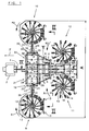
- FIG. 1 the basic structure of an inventive Haymaking machine can be seen over a trestle 1 on an agricultural tractor 2 is coupled.
- Support frame 3 which is pivotable about a vertical axis is connected to the trestle 1.
- a chassis 4 which is equipped with wheels 5,6,7,8.
- the haymaking machine includes front rotary rakes 9,10 and rear rotary rakes 11,12, the support frame 3 are assigned in a V-shaped arrangement and about itself the driving and working direction F of the haymaking machine adapting training wheels Support 13 against the ground.
- the rotary rakes 9,10,11,12 in turn have tines 14 stocked Tine arms 15 on which within a gyro housing 16 are stored and from a non-illustrated Control cam within the gyro 16 are controllable.
- all rotary rakes 9,10,11,12 be executed so that from the outer Tines 14 of the tine arms 15 described diameter are the same size or only the front Rotary rake 9,10 and the rear rotary rakes 11.12 have the same diameter.
- the rotary rakes 9,10,11,12 provided with tine arms 15, the tines 14 in use describe equal diameter.
- a haymaking machine can be a continuous area with a total working width A be edited, the total working width A in a range of 12 to 15 m or can still lie over it.
- the direction of rotation of the rotary rakes 9,10,11,12 corresponds to the respective direction of rotation arrows R1 and R2, so that in the middle behind the rear inner rotary rake 11,12 a swath filed can be for a subsequent mission Large machines such as Feldhburgseler or the like. the right size.
- the front rotary rakes 9,10 on support and drive assemblies 17,18 at articulation points 19,20 two transverse to Travel and working direction F displaceable on the supporting frame 3 of the haymaking machine supported sliding frame 21,22 in the direction of travel and direction F directed Swivel axes 23,24 stored and can thus by a Pivoting movement about the pivot axes 23,24 from a ground parallel working and operating position in one at least approximately vertical transport position and back be transferred.
- the carrying and driving arrangements 17,18 are, as this particular from Fig.2 and Figure 3 is seen, designed as an angle lever, wherein the long legs 25 of the support and drive assemblies 17,18 formed variable in length are.
- hydraulic piston-cylinder assemblies 26,27 are provided for changing the length of the long legs 25.
- hydraulic piston-cylinder assemblies 26,27 are simultaneously or temporally offset with hydraulic piston-cylinder arrangements 28,29 for the transfer of the rotary rakes 9,10 from the Work and operating position in a transport position and back from a hydraulic power source with Pressure medium can be applied.
- the support and drive assemblies 17,18 so formed be, as disclosed in DE 197 16 379 C1.
- the sash 21,22 and the receiving pockets 32,33,34,35 slide guides 21,22,32,33,34,35.
- the receiving pockets are 32, 33 and 34, 35 mounted one above the other, so that thereby a longer and thus better guidance of the carrier 30 in the receiving pockets 32,33,34,35 can be reached.
- the receiving pockets 32,33 and 34,35 next to each other, so that then the sliding frames 21,22 are designed to be identical can.
- carrier 30th To ensure the sliding frame 21,22, the inner sides the receiving pockets 32,33,34,35 with plate-shaped, preferably made of a resistant Plastic-made guide rails fitted, the over the entire length of the receiving pockets 32,33,34,35 extend.
- the guide rails can be split, with one first section at the outer ends of the receiving pockets 32,33,34,35 and a second section on the straps 30 of the sliding frame 21,22 are attached.
- Fig.1 comprises the rear part of the haymaking machine more rotary rakes 11,12, which also about support and drive assemblies 40.41 in driving and working direction F directed Schenkachsen 42,43 pivotally mounted on the support frame 3 are stored and thus by a pivoting movement from the ground-parallel working and operating position in an approximately vertical transport position and can be transferred back.
- the support and drive assemblies 40,41 also formed variable in length.
- the haymaking machine by a four wheels 5,6,7,8 encompassende Tandem axle 44 supported against the ground, wherein the tandem axle 44 via support arms 45,46 on the support frame 3 is pivotally mounted and the wheels 5,6,7,8 at around a horizontal and transverse to the driving and Working direction F directed axis pivotally mounted Achsschwingen 47 are articulated.
- This can the support frame 3 of the haymaking machine from a Work and operating position and a high stability permitting minimal ground clearance Basic position in a greater ground clearance having Raised position and thus in an advantageous Way in concrete individual situations with a larger one Ground clearance are operated while the haymaking machine usually in a position with the lowest possible Ground clearance and the greatest possible stability remains.
- a change in the ground clearance of the Haymaking machine can be over between the support frame 3 and the support arms 45,46 extending hydraulic Piston-cylinder assemblies 48,49 done.
- the rear wheels 7.8 of the tandem axle 44th a reduced relative to the front wheels 5.6 Have track width, whereby the space between the front rotary rake 9,10 and the rear rotary rake 11,12 to a minimum and thus the overall length the haymaking machine are kept small can.
- the Haymaking machine on a drive concept in which one approximately midway between the front rotary rakes 9,10 and the rear rotary rake 11,12 on the support frame 3 arranged central drive unit 50 with an output for each rotary rakes 9,10,11,12 provided is.
- the central drive unit 50 includes Gear units 51,52,53,54,55, which is characterized by a Distinguish modular construction.
- gear units 51,52,54,55 can be a structurally identical, for example from a bevel gear shaft, a gear cover and Bearings existing mounting unit 58 are used.
- drive shafts 59,60,61,62 are provided, which in another possible embodiment be replaced by a through shaft could.
Landscapes
- Life Sciences & Earth Sciences (AREA)
- Environmental Sciences (AREA)
- Agricultural Machines (AREA)
- Soil Working Implements (AREA)
- Folding Of Thin Sheet-Like Materials, Special Discharging Devices, And Others (AREA)
- Handcart (AREA)
- Control Of Multiple Motors (AREA)
- Glass Compositions (AREA)
- Paper (AREA)
Claims (21)
- Machine de fenaison, en particulier pour l'andainage des tiges et des feuilles dans l'agriculture, comportant quatre roues racleuses (9, 10, 11,12) ou éléments racleurs similaires entraínés en rotation autour d'axes verticaux, s'appuyant au moyen de roues d'appui (13) par rapport au sol et présentant des bras dentés (15) munis de dents (14), dont au moins les roues racleuses (9, 10) disposées en avant dans la direction de marche (F) sont mobiles dans la direction horizontale, perpendiculairement à la direction de marche, et les roues racleuses (9, 10, 11,12) sont translatables à partir d'une position approximativement horizontale de travail et de fonctionnement dans une position de transport au moins approximativement verticale et vice-versa au moyen de dispositifs de support et d'entraínement (17, 18, 40, 41) logés des deux côtés sur un châssis porteur (3) muni de roues de roulement, autour d'axes de pivotement (23, 24, 42, 43) orientés dans la direction de marche (F), et les dispositifs de support et d'entraínement (17, 18,40,41) prennent, dans la position de travail et de fonctionnement, une position orientée vers l'extérieur à partir du châssis porteur (3) et, dans la position de transport, une position orientée vers le haut à partir du châssis porteur (3),
caractérisée en ce que
les emplacements d'articulation (19, 20), présentant des axes de pivotement (23, 24), des dispositifs de support et d'entraínement (17, 18) des roues racleuses avant (9, 10) sont maintenus respectivement sur des guidages de coulissement (21, 22, 32, 33, 34, 35) reliés avec le châssis porteur (3) et les dispositifs de support et d'entraínement (17, 18) peuvent exécuter, avec les roues racleuses avant (9, 10), au moyen de guidages de coulissement (21, 22, 32, 33, 34, 35), un déplacement perpendiculaire à la direction de marche (F), et orienté pour l'essentiel dans la direction horizontale et vers le haut, et vice-versa. - Machine de fenaison selon la revendication 1,
caractérisée en ce que
les guidages de coulissement (21, 22, 32, 33, 34, 35) pour le maintien des dispositifs de support et d'entraínement (17, 18) sont composés de châssis coulissants (21, 22) et de poches de réception (32, 33, 34, 35) orientées perpendiculairement à la direction de marche (F) et maintenues sur le châssis porteur (3). - Machine de fenaison selon la revendication 2,
caractérisée en ce que
les emplacements d'articulation (19, 20), présentant des axes de pivotement (23, 24), des dispositifs de support et d'entraínement (17, 18) sont maintenus sur les châssis coulissants (21, 22). - Machine de fenaison selon l'une des revendications 2 ou 3,
caractérisée en ce que
les châssis coulissants (21, 22) des guidages de coulissement (21, 22, 32, 33, 34, 35) sont guidés, de façon à être mobiles et arrêtés, dans les poches de réception (32, 33, 34, 35) orientées perpendiculairement à la direction de marche (F) et maintenues sur le châssis porteur (3). - Machine de fenaison selon l'une des revendications 1 à 4,
caractérisée en ce que
la translation des châssis coulissants (21, 22) dans les poches de réception (32, 33, 34, 35), permet un agrandissement ou un rétrécissement en continu de la largeur totale de travail de la machine de fenaison. - Machine de fenaison selon l'une des revendications 2 à 5,
caractérisée en ce que
les guidages de coulissement (21, 22, 32, 33, 34, 35) sont maintenus sur le châssis porteur (3) de manière, qu'entre les châssis coulissants (21, 22) et le sol, il reste seulement une garde au sol minimale nécessaire pendant le service. - Machine de fenaison selon l'une des revendications 2 à 6,
caractérisée en ce que
les châssis coulissants (21, 22) sont constitués de supports (30, 31) composés pour avoir une forme de base en U. - Machine de fenaison selon la revendication 7,
caractérisée en ce que
les supports (30, 31) des châssis coulissants (21, 22) ont une section de tube de forme carrée. - Machine de fenaison selon la revendication 7,
caractérisée en ce que
les poches de réception (32, 33, 34, 35) ont également une section de forme carrée. - Machine de fenaison selon l'une des revendications 2 à 9,
caractérisée en ce que
les poches de réception (32, 34) pour le châssis coulissant (21) sont disposées au-dessus ou en dessous des poches de réception (33, 35) pour l'autre châssis coulissant (22). - Machine de fenaison selon l'une des revendications 2 à 9,
caractérisée en ce que
les poches de réception (32, 34) pour le châssis coulissant (21) et les poches de réception (33, 35) pour l'autre châssis coulissant (22) sont montées l'une près de l'autre. - Machine de fenaison selon l'une des revendications 2 à 11,
caractérisée en ce que
des éléments de réglage (36, 37) produisent une force de traction et de pression pour le déplacement et pour le blocage des châssis coulissants (21,22) dans les poches de réception (32, 33, 34, 35). - Machine de fenaison selon la revendication 12,
caractérisée en ce que
les éléments de réglage (36, 37) produisant une force de traction et de pression sont des dispositifs hydrauliques à pistons-vérins (38, 39). - Machine de fenaison selon l'une des revendications 1 à 13,
caractérisée en ce qu'
une unité centrale d'entraínement (50), qui présente un entraínement pour chaque roue racleuse (9, 10, 11, 12), est disposée sur le châssis porteur (3). - Machine de fenaison selon l'une des revendications 1 à 14,
caractérisée en ce que
l'unité centrale d'entraínement (50) est formée d'unités de transmission (51, 52, 53, 54, 55) disposées sur un longeron de transmission (57) s'étendant perpendiculairement à la direction de marche et de travail (F). - Machine de fenaison selon l'une des revendications 1 à 15,
caractérisée en ce que
le longeron de transmission (57) de l'unité centrale d'entraínement (50) est monté, vu dans la direction de marche et de travail (F), entre les roues racleuses avant (9, 10) et les roues racleuses arrière (11, 12). - Machine de fenaison selon l'une des revendications 1 à 16,
caractérisée en ce que
les unités de transmission (51, 52, 53, 54, 55) de l'unité centrale d'entraínement (50) présentent un carter de transmission (56) de même type. - Machine de fenaison selon l'une des revendications 1 à 17,
caractérisée en ce qu'
il est prévu, pour l'appui du châssis porteur (3) par rapport au sol, un axe en tandem (44) avec roues de roulement (5, 6, 7, 8). - Machine de fenaison selon l'une des revendications 1 à 18,
caractérisée en ce que
pour l'appui du châssis porteur (3) par rapport au sol, un axe en tandem (44) avec roues de roulement (5, 6, 7, 8), permet de lever le châssis porteur (3), à partir d'une position de base permettant une position de travail et de fonctionnement et garantissant une grande stabilité statique grâce à une garde au sol minimale, à une position présentant une plus grande garde au sol. - Machine de fenaison selon l'une des revendications 1 à 19,
caractérisée en ce que
pour mettre en place avec variation en hauteur l'axe en tandem (44) avec les roues de roulement (5, 6, 7, 8), des bras de support (45, 46) logés de manière pivotante sur le châssis porteur (3), peuvent être actionnés par des dispositifs hydrauliques à pistons-vérins (48, 49). - °) Machine de fenaison selon l'une des revendications 1 à 20,
caractérisée en ce que
les roues de roulement arrière (7, 8) de l'axe en tandem (44) présentent un écartement de voie réduit par rapport aux roues de roulement avant (5, 6).
Applications Claiming Priority (2)
| Application Number | Priority Date | Filing Date | Title |
|---|---|---|---|
| DE19952555 | 1999-11-01 | ||
| DE19952555A DE19952555C2 (de) | 1999-11-01 | 1999-11-01 | Heuwerbungsmaschine |
Publications (2)
| Publication Number | Publication Date |
|---|---|
| EP1095555A1 EP1095555A1 (fr) | 2001-05-02 |
| EP1095555B1 true EP1095555B1 (fr) | 2004-09-22 |
Family
ID=7927571
Family Applications (1)
| Application Number | Title | Priority Date | Filing Date |
|---|---|---|---|
| EP00122756A Expired - Lifetime EP1095555B1 (fr) | 1999-11-01 | 2000-10-19 | Machine de fenaison |
Country Status (3)
| Country | Link |
|---|---|
| EP (1) | EP1095555B1 (fr) |
| AT (1) | ATE276645T1 (fr) |
| DE (2) | DE19952555C2 (fr) |
Cited By (4)
| Publication number | Priority date | Publication date | Assignee | Title |
|---|---|---|---|---|
| US9277690B2 (en) | 2010-03-08 | 2016-03-08 | Forage Innovations B.V. | Haymaking device |
| DE102018116014A1 (de) | 2018-07-02 | 2020-01-02 | Claas Saulgau Gmbh | Landwirtschaftliches Arbeitsgerät |
| EP3892085A1 (fr) | 2020-04-08 | 2021-10-13 | PÖTTINGER Landtechnik GmbH | Procédé de fonctionnement d'un andaineuse multirotative et andaineuse multirotative |
| RU208646U1 (ru) * | 2021-08-26 | 2021-12-29 | Общество с ограниченной ответственностью "Новосибирский опытно-экспериментальный завод нестандартизированного оборудования" | Сеноуборочное устройство |
Families Citing this family (10)
| Publication number | Priority date | Publication date | Assignee | Title |
|---|---|---|---|---|
| FR2828988B1 (fr) * | 2001-09-06 | 2004-07-30 | Kuhn Sa | Machine de fenaison comportant des rotors lies a des bras porteurs realises en deux parties telescopiques |
| DE20207865U1 (de) | 2002-05-21 | 2003-10-02 | Kverneland Asa, Kverneland | Heuwerbungsmaschine |
| DE10327901C5 (de) * | 2003-06-20 | 2011-11-17 | Maschinenfabrik Bernard Krone Gmbh | Heuwerbungsmaschine |
| DE10327884B4 (de) * | 2003-06-20 | 2006-01-05 | Maschinenfabrik Bernard Krone Gmbh | Heuwerbungsmaschine |
| DE102004058461A1 (de) * | 2004-12-03 | 2006-06-14 | Maschinenfabrik Bernard Krone Gmbh | Heuwerbungsmaschine |
| DE102007053566A1 (de) * | 2007-11-09 | 2009-05-14 | Alois Pöttinger Maschinenfabrik Gmbh | Heuwerbungsmaschine |
| NL1037785C2 (nl) | 2010-03-08 | 2011-09-09 | Forage Innovations Bv | Hooibouwinrichting. |
| NL1037782C2 (nl) | 2010-03-08 | 2011-09-09 | Forage Innovations Bv | Hooibouwinrichting. |
| DE102016012522A1 (de) * | 2016-10-20 | 2018-04-26 | Maschinenfabrik Bernard Krone GmbH & Co. KG | Heuwerbungsmaschine mit modularer Anbauvorrichtung |
| DE102019104755A1 (de) * | 2019-02-25 | 2020-08-27 | Horsch Maschinen Gmbh | Bodenbearbeitungsmaschine, insbesondere Hackgerät |
Family Cites Families (6)
| Publication number | Priority date | Publication date | Assignee | Title |
|---|---|---|---|---|
| DE4405858C1 (de) * | 1994-02-23 | 1995-06-01 | Fortschritt Erntemaschinen | Aufhängung für ein- oder beidseitig an einem Trägerfahrzeug angebrachte Arbeitsaggregate |
| DE29521619U1 (de) * | 1995-12-15 | 1997-11-27 | Claas Saulgau Gmbh, 88348 Saulgau | Kreiselschwader |
| FR2759245B1 (fr) * | 1997-02-11 | 1999-04-23 | Kuhn Sa | Machine de fenaison avec un dispositif d'appui au sol incluant au moins un balancier avec deux roues porteuses et un moyen pour deplacer ce balancier en vue du transport |
| DE19716379C1 (de) * | 1997-04-18 | 1998-06-18 | Krone Bernhard Gmbh Maschf | Heuwerbungsmaschine |
| NL1006945C2 (nl) * | 1997-09-04 | 1999-03-05 | Arend Mulder | Werktuigdrager. |
| DE29818457U1 (de) * | 1998-10-15 | 1998-12-17 | Multinorm B.V., Nieuw-Vennep | Landwirtschaftliche Bearbeitungsmaschine |
-
1999
- 1999-11-01 DE DE19952555A patent/DE19952555C2/de not_active Expired - Fee Related
-
2000
- 2000-10-19 AT AT00122756T patent/ATE276645T1/de active
- 2000-10-19 DE DE50007864T patent/DE50007864D1/de not_active Expired - Lifetime
- 2000-10-19 EP EP00122756A patent/EP1095555B1/fr not_active Expired - Lifetime
Cited By (4)
| Publication number | Priority date | Publication date | Assignee | Title |
|---|---|---|---|---|
| US9277690B2 (en) | 2010-03-08 | 2016-03-08 | Forage Innovations B.V. | Haymaking device |
| DE102018116014A1 (de) | 2018-07-02 | 2020-01-02 | Claas Saulgau Gmbh | Landwirtschaftliches Arbeitsgerät |
| EP3892085A1 (fr) | 2020-04-08 | 2021-10-13 | PÖTTINGER Landtechnik GmbH | Procédé de fonctionnement d'un andaineuse multirotative et andaineuse multirotative |
| RU208646U1 (ru) * | 2021-08-26 | 2021-12-29 | Общество с ограниченной ответственностью "Новосибирский опытно-экспериментальный завод нестандартизированного оборудования" | Сеноуборочное устройство |
Also Published As
| Publication number | Publication date |
|---|---|
| ATE276645T1 (de) | 2004-10-15 |
| EP1095555A1 (fr) | 2001-05-02 |
| DE19952555A1 (de) | 2001-05-10 |
| DE50007864D1 (de) | 2004-10-28 |
| DE19952555C2 (de) | 2003-08-07 |
Similar Documents
| Publication | Publication Date | Title |
|---|---|---|
| DE69705807T2 (de) | Heuwerbungsmaschine | |
| EP0872170B1 (fr) | Machine de fenaison | |
| EP2067397B1 (fr) | Tête de récolte servant à cueillir et transporter des céréales pour une récolteuse agricole | |
| EP1095555B1 (fr) | Machine de fenaison | |
| EP0339231A2 (fr) | Machine agricole de fauchage et de fenaison | |
| DE2601304A1 (de) | Landmaschine mit mindestens zwei um stehende achsen umlaufenden rechraedern | |
| DE60210550T2 (de) | Heuwerbungsmaschine | |
| EP1093708A1 (fr) | Dispositif faucheur | |
| DE69613191T2 (de) | Heuwerbungsmaschine mit mindestens einem Rotor zum Schwaden | |
| DE60112351T2 (de) | Heuwerbungsmaschine | |
| EP0116661A1 (fr) | Dispositif de fauchage | |
| DE69209361T2 (de) | Verbesserter Pflanzenschwader | |
| DE102008042392B4 (de) | Erntevorsatz für landwirtschaftliche Erntemaschinen | |
| DE69519829T2 (de) | Heuwerbungsmaschine, namentlich ein Schwader mit gesteuerten Zinkentragarmen | |
| DE69705013T2 (de) | Heuwerbungsmaschine | |
| DE9216498U1 (de) | Heuwerbungsmaschine | |
| EP0548720A2 (fr) | Machine de fenaison | |
| DE29818457U1 (de) | Landwirtschaftliche Bearbeitungsmaschine | |
| DE29708799U1 (de) | Mehrkreiseliger Großschwader | |
| DE69705337T2 (de) | Heuwerbungsmaschine | |
| DE4142496C2 (de) | Heuwerbungsmaschine | |
| AT501972B1 (de) | Mähmaschine | |
| DE9305014U1 (de) | Heuwerbungsmaschine | |
| DE4201881A1 (de) | Heuwerbungsmaschine | |
| DE4428288C2 (de) | Landwirtschaftliches Arbeitsgerät, insbesondere Mulchgerät |
Legal Events
| Date | Code | Title | Description |
|---|---|---|---|
| PUAI | Public reference made under article 153(3) epc to a published international application that has entered the european phase |
Free format text: ORIGINAL CODE: 0009012 |
|
| AK | Designated contracting states |
Kind code of ref document: A1 Designated state(s): AT BE CH CY DE DK ES FI FR GB GR IE IT LI LU MC NL PT SE |
|
| AX | Request for extension of the european patent |
Free format text: AL;LT;LV;MK;RO;SI |
|
| 17P | Request for examination filed |
Effective date: 20011012 |
|
| AKX | Designation fees paid |
Free format text: AT BE CH CY DE DK ES FI FR GB GR IE IT LI LU MC NL PT SE |
|
| 17Q | First examination report despatched |
Effective date: 20030814 |
|
| GRAP | Despatch of communication of intention to grant a patent |
Free format text: ORIGINAL CODE: EPIDOSNIGR1 |
|
| GRAS | Grant fee paid |
Free format text: ORIGINAL CODE: EPIDOSNIGR3 |
|
| GRAA | (expected) grant |
Free format text: ORIGINAL CODE: 0009210 |
|
| AK | Designated contracting states |
Kind code of ref document: B1 Designated state(s): AT BE CH CY DE DK ES FI FR GB GR IE IT LI LU MC NL PT SE |
|
| PG25 | Lapsed in a contracting state [announced via postgrant information from national office to epo] |
Ref country code: IT Free format text: LAPSE BECAUSE OF FAILURE TO SUBMIT A TRANSLATION OF THE DESCRIPTION OR TO PAY THE FEE WITHIN THE PRESCRIBED TIME-LIMIT;WARNING: LAPSES OF ITALIAN PATENTS WITH EFFECTIVE DATE BEFORE 2007 MAY HAVE OCCURRED AT ANY TIME BEFORE 2007. THE CORRECT EFFECTIVE DATE MAY BE DIFFERENT FROM THE ONE RECORDED. Effective date: 20040922 Ref country code: GB Free format text: LAPSE BECAUSE OF FAILURE TO SUBMIT A TRANSLATION OF THE DESCRIPTION OR TO PAY THE FEE WITHIN THE PRESCRIBED TIME-LIMIT Effective date: 20040922 Ref country code: IE Free format text: LAPSE BECAUSE OF FAILURE TO SUBMIT A TRANSLATION OF THE DESCRIPTION OR TO PAY THE FEE WITHIN THE PRESCRIBED TIME-LIMIT Effective date: 20040922 Ref country code: CY Free format text: LAPSE BECAUSE OF FAILURE TO SUBMIT A TRANSLATION OF THE DESCRIPTION OR TO PAY THE FEE WITHIN THE PRESCRIBED TIME-LIMIT Effective date: 20040922 Ref country code: FI Free format text: LAPSE BECAUSE OF FAILURE TO SUBMIT A TRANSLATION OF THE DESCRIPTION OR TO PAY THE FEE WITHIN THE PRESCRIBED TIME-LIMIT Effective date: 20040922 |
|
| REG | Reference to a national code |
Ref country code: GB Ref legal event code: FG4D Free format text: NOT ENGLISH |
|
| REG | Reference to a national code |
Ref country code: CH Ref legal event code: EP |
|
| PG25 | Lapsed in a contracting state [announced via postgrant information from national office to epo] |
Ref country code: LU Free format text: LAPSE BECAUSE OF NON-PAYMENT OF DUE FEES Effective date: 20041019 |
|
| REG | Reference to a national code |
Ref country code: IE Ref legal event code: FG4D Free format text: GERMAN |
|
| REF | Corresponds to: |
Ref document number: 50007864 Country of ref document: DE Date of ref document: 20041028 Kind code of ref document: P |
|
| PG25 | Lapsed in a contracting state [announced via postgrant information from national office to epo] |
Ref country code: LI Free format text: LAPSE BECAUSE OF NON-PAYMENT OF DUE FEES Effective date: 20041031 Ref country code: CH Free format text: LAPSE BECAUSE OF NON-PAYMENT OF DUE FEES Effective date: 20041031 Ref country code: BE Free format text: LAPSE BECAUSE OF NON-PAYMENT OF DUE FEES Effective date: 20041031 Ref country code: MC Free format text: LAPSE BECAUSE OF NON-PAYMENT OF DUE FEES Effective date: 20041031 |
|
| PG25 | Lapsed in a contracting state [announced via postgrant information from national office to epo] |
Ref country code: SE Free format text: LAPSE BECAUSE OF FAILURE TO SUBMIT A TRANSLATION OF THE DESCRIPTION OR TO PAY THE FEE WITHIN THE PRESCRIBED TIME-LIMIT Effective date: 20041222 Ref country code: GR Free format text: LAPSE BECAUSE OF FAILURE TO SUBMIT A TRANSLATION OF THE DESCRIPTION OR TO PAY THE FEE WITHIN THE PRESCRIBED TIME-LIMIT Effective date: 20041222 Ref country code: DK Free format text: LAPSE BECAUSE OF FAILURE TO SUBMIT A TRANSLATION OF THE DESCRIPTION OR TO PAY THE FEE WITHIN THE PRESCRIBED TIME-LIMIT Effective date: 20041222 |
|
| PG25 | Lapsed in a contracting state [announced via postgrant information from national office to epo] |
Ref country code: ES Free format text: LAPSE BECAUSE OF FAILURE TO SUBMIT A TRANSLATION OF THE DESCRIPTION OR TO PAY THE FEE WITHIN THE PRESCRIBED TIME-LIMIT Effective date: 20050102 |
|
| GBV | Gb: ep patent (uk) treated as always having been void in accordance with gb section 77(7)/1977 [no translation filed] |
Effective date: 20040922 |
|
| REG | Reference to a national code |
Ref country code: IE Ref legal event code: FD4D |
|
| BERE | Be: lapsed |
Owner name: MASCHINENFABRIK BERNARD KRONE G.M.B.H. Effective date: 20041031 |
|
| REG | Reference to a national code |
Ref country code: CH Ref legal event code: PL |
|
| ET | Fr: translation filed | ||
| PLBE | No opposition filed within time limit |
Free format text: ORIGINAL CODE: 0009261 |
|
| STAA | Information on the status of an ep patent application or granted ep patent |
Free format text: STATUS: NO OPPOSITION FILED WITHIN TIME LIMIT |
|
| 26N | No opposition filed |
Effective date: 20050623 |
|
| BERE | Be: lapsed |
Owner name: MASCHINENFABRIK BERNARD *KRONE G.M.B.H. Effective date: 20041031 |
|
| PG25 | Lapsed in a contracting state [announced via postgrant information from national office to epo] |
Ref country code: PT Free format text: LAPSE BECAUSE OF NON-PAYMENT OF DUE FEES Effective date: 20050222 |
|
| REG | Reference to a national code |
Ref country code: FR Ref legal event code: PLFP Year of fee payment: 16 |
|
| REG | Reference to a national code |
Ref country code: FR Ref legal event code: PLFP Year of fee payment: 17 |
|
| REG | Reference to a national code |
Ref country code: FR Ref legal event code: PLFP Year of fee payment: 18 |
|
| PGFP | Annual fee paid to national office [announced via postgrant information from national office to epo] |
Ref country code: AT Payment date: 20171010 Year of fee payment: 18 Ref country code: NL Payment date: 20171026 Year of fee payment: 18 |
|
| REG | Reference to a national code |
Ref country code: FR Ref legal event code: PLFP Year of fee payment: 19 |
|
| PGFP | Annual fee paid to national office [announced via postgrant information from national office to epo] |
Ref country code: DE Payment date: 20181018 Year of fee payment: 19 |
|
| PGFP | Annual fee paid to national office [announced via postgrant information from national office to epo] |
Ref country code: FR Payment date: 20181029 Year of fee payment: 19 |
|
| REG | Reference to a national code |
Ref country code: NL Ref legal event code: MM Effective date: 20181101 |
|
| REG | Reference to a national code |
Ref country code: AT Ref legal event code: MM01 Ref document number: 276645 Country of ref document: AT Kind code of ref document: T Effective date: 20181019 |
|
| PG25 | Lapsed in a contracting state [announced via postgrant information from national office to epo] |
Ref country code: NL Free format text: LAPSE BECAUSE OF NON-PAYMENT OF DUE FEES Effective date: 20181101 |
|
| PG25 | Lapsed in a contracting state [announced via postgrant information from national office to epo] |
Ref country code: AT Free format text: LAPSE BECAUSE OF NON-PAYMENT OF DUE FEES Effective date: 20181019 |
|
| REG | Reference to a national code |
Ref country code: DE Ref legal event code: R119 Ref document number: 50007864 Country of ref document: DE |
|
| PG25 | Lapsed in a contracting state [announced via postgrant information from national office to epo] |
Ref country code: DE Free format text: LAPSE BECAUSE OF NON-PAYMENT OF DUE FEES Effective date: 20200501 |
|
| PG25 | Lapsed in a contracting state [announced via postgrant information from national office to epo] |
Ref country code: FR Free format text: LAPSE BECAUSE OF NON-PAYMENT OF DUE FEES Effective date: 20191031 |