EP0428113B1 - Abstellplatz für Container - Google Patents
Abstellplatz für Container Download PDFInfo
- Publication number
- EP0428113B1 EP0428113B1 EP90121642A EP90121642A EP0428113B1 EP 0428113 B1 EP0428113 B1 EP 0428113B1 EP 90121642 A EP90121642 A EP 90121642A EP 90121642 A EP90121642 A EP 90121642A EP 0428113 B1 EP0428113 B1 EP 0428113B1
- Authority
- EP
- European Patent Office
- Prior art keywords
- container
- stand
- frame
- trough
- vessels according
- Prior art date
- Legal status (The legal status is an assumption and is not a legal conclusion. Google has not performed a legal analysis and makes no representation as to the accuracy of the status listed.)
- Revoked
Links
Images


Classifications
-
- B—PERFORMING OPERATIONS; TRANSPORTING
- B65—CONVEYING; PACKING; STORING; HANDLING THIN OR FILAMENTARY MATERIAL
- B65D—CONTAINERS FOR STORAGE OR TRANSPORT OF ARTICLES OR MATERIALS, e.g. BAGS, BARRELS, BOTTLES, BOXES, CANS, CARTONS, CRATES, DRUMS, JARS, TANKS, HOPPERS, FORWARDING CONTAINERS; ACCESSORIES, CLOSURES, OR FITTINGS THEREFOR; PACKAGING ELEMENTS; PACKAGES
- B65D90/00—Component parts, details or accessories for large containers
- B65D90/12—Supports
- B65D90/125—Docking stations, i.e. for the temporary support of the container
-
- B—PERFORMING OPERATIONS; TRANSPORTING
- B65—CONVEYING; PACKING; STORING; HANDLING THIN OR FILAMENTARY MATERIAL
- B65D—CONTAINERS FOR STORAGE OR TRANSPORT OF ARTICLES OR MATERIALS, e.g. BAGS, BARRELS, BOTTLES, BOXES, CANS, CARTONS, CRATES, DRUMS, JARS, TANKS, HOPPERS, FORWARDING CONTAINERS; ACCESSORIES, CLOSURES, OR FITTINGS THEREFOR; PACKAGING ELEMENTS; PACKAGES
- B65D90/00—Component parts, details or accessories for large containers
- B65D90/22—Safety features
- B65D90/24—Spillage-retaining means, e.g. recovery ponds
-
- E—FIXED CONSTRUCTIONS
- E04—BUILDING
- E04B—GENERAL BUILDING CONSTRUCTIONS; WALLS, e.g. PARTITIONS; ROOFS; FLOORS; CEILINGS; INSULATION OR OTHER PROTECTION OF BUILDINGS
- E04B1/00—Constructions in general; Structures which are not restricted either to walls, e.g. partitions, or floors or ceilings or roofs
- E04B1/343—Structures characterised by movable, separable, or collapsible parts, e.g. for transport
- E04B1/34305—Structures characterised by movable, separable, or collapsible parts, e.g. for transport telescopic
-
- E—FIXED CONSTRUCTIONS
- E04—BUILDING
- E04B—GENERAL BUILDING CONSTRUCTIONS; WALLS, e.g. PARTITIONS; ROOFS; FLOORS; CEILINGS; INSULATION OR OTHER PROTECTION OF BUILDINGS
- E04B7/00—Roofs; Roof construction with regard to insulation
- E04B7/16—Roof structures with movable roof parts
- E04B7/166—Roof structures with movable roof parts characterised by a translation movement of the movable roof part, with or without additional movements
-
- E—FIXED CONSTRUCTIONS
- E04—BUILDING
- E04H—BUILDINGS OR LIKE STRUCTURES FOR PARTICULAR PURPOSES; SWIMMING OR SPLASH BATHS OR POOLS; MASTS; FENCING; TENTS OR CANOPIES, IN GENERAL
- E04H5/00—Buildings or groups of buildings for industrial or agricultural purposes
- E04H5/02—Buildings or groups of buildings for industrial purposes, e.g. for power-plants or factories
Definitions
- the invention relates to a storage space for containers in which soil-damaging materials are stored, a collecting device with a collecting container and a cover being provided below the container.
- Such a storage space for containers is known from CH-A 543 430.
- the storage device has a tank, the top of which is designed as a storage space for barrels and containers.
- the liquid emerging from the drums or containers can flow through an opening into the tank.
- the parking space has a cover which is fixedly attached to the tank and whose side walls can be folded up.
- the entire storage space is designed to be portable and is therefore only suitable for storing smaller drums or containers.
- the teaching of the document NL-A 8 800 624 relates to a covering device for a container, the covering device being articulated on supports fastened to foundations, which are arranged on the side of the container, and the covering device being hinged by means of a pivoting device.
- the covering device is intended to protect the container, which is deposited directly on the floor adjacent to the foundations, against the ingress of rain into the interior of the container.
- the object of the present invention is to provide a storage or disposal area for containers which prevents damage to the soil by penetration of harmful substances in the area of the parking space, the size of the containers or barrels not being limited to small containers or small barrels should be.
- the object of the invention is achieved in that the container as a container with an upper filling area for receiving parts, e.g. Scrap chips, scrap stampings and the like.
- the collecting device has a trough, that a frame accommodating the container is provided, that supports are fastened to the frame, which extend to the bottom of the trough and that the cover can be folded up Roof or sliding roof is formed, the roofs release the filling area of the container after folding up or moving.
- the trough is advantageously made from building materials, for example reinforced concrete, the trough being provided on the inside with a sealant, for example epoxy resin.
- the trough can be made of corrosion-resistant material, for example hot-dip galvanized steel.
- the tub is dug as a pit and this is carried out in concrete or reinforced concrete.
- a tub can be provided which is placed on leveled or appropriately prepared floor. The tub can - but this does not necessarily have to be the case - connect to a ramp, the upper edge of the tub corresponding approximately to the height of the ramp.
- the frame is preferably rust-like and has a collecting funnel on its underside, the mouth of which is connected to a tank.
- the tank is advantageously offset, preferably arranged in the longitudinal direction of the frame, and covered with a closable additional opening which adjoins the frame. On the one hand this results in a flat upper surface of the pit or the tub on the other hand good access to the tank, so that the liquid accumulated there can be removed and disposed of, for example with a pump.
- the tank sits in a recess or a sump, so that in this area, even in the event of leaks on the collecting funnel, the line or the tank, all the liquids collect, which in turn are collected by the dense trough.
- a collecting and a storage container can be provided instead of the tank, the liquid being collected in the collecting container and from there, e.g. by means of a float-controlled pump into the reservoir.
- the collecting and / or the storage container and / or the tank can also be arranged below the frame or collecting funnel, in which case a cleaning or access flap can also be arranged laterally. Depending on the position of the flap, tightness must be ensured.
- the trough and / or the tank advantageously has a leakage warning device which indicates any leaks.
- posts are provided, in particular on a long side of the parking space, to which a fold-up roof is attached. Folding up is important because the containers are usually transported by means of a skip loader that has lifting arms that reach the container from above.
- a section roof is attached in an inverted U-shape over the filling area of the container or the storage place.
- the individual segments are designed to overlap one another and can be gradually extended and retracted, the space required when the section roof is retracted advantageously requiring only the space of one segment.
- the structure of the cover according to the invention further provides horizontally arranged rails which are arranged on or on a support frame and in which the segments are longitudinally displaceable.
- Each segment is advantageously assigned its own rail, which are arranged at a parallel distance from one another.
- the claimed rail arrangement furthermore ensures that material falling to the side of the container can fall through when filling between the rails and does not hinder a shifting of the section roof.
- Another embodiment provides profile wheels, by means of which the individual segments roll smoothly in or on the rails in order to achieve a low drive power and easy manual displacement of the section roof.
- the structure of the section roof according to the invention provides stops or drivers in the individual segments, through which a coupling between the one and a drive provided segment and the other segments takes place, the displacement of an adjacent segment takes place only after reaching a travel path that corresponds to the longitudinal extent of the overlapping segment. Due to the pulling or pushing movement of the individual segments, they are each provided with stops at the end in the direction of the longitudinal axis of the section roof.
- a one-sided extension of the rails allows the container, in particular its filling area, to be completely exposed when the section roof is retracted, thus ensuring optimal accessibility.
- the segment pointing in the direction of the rail extension is extended according to the invention or rigidly coupled to a further segment, which has an inward slope at the free end to limit the protrusion dimension.
- All segments are further equipped with an element that engages behind the rail area or support frame, e.g. in the form of a lever on the side facing the container, which represents a rear bracket and are used to protect against "derailment” and to protect a segment from wind.
- an element that engages behind the rail area or support frame e.g. in the form of a lever on the side facing the container, which represents a rear bracket and are used to protect against "derailment” and to protect a segment from wind.
- a motor drive is provided for moving the section roof.
- the drive is preferably provided with a one-sided chain drive, for example in the form of a revolving chain into which a drive pinion of an electric motor engages.
- a folding latch or swivel lever For coupling the drive between the segment and the circulation chain, it makes sense to provide components, such as a folding latch or swivel lever, which allow the segment drive to be released quickly and easily in order to move the section roof by hand in the event of a power failure or a malfunction in the drive can.
- An installation arrangement of the circulation chain below the rails or in a largely covered housing reduces the risk of accidents and at the same time protects the drive chain from dirt and consequently increases the availability of the drive.
- a pushbutton or hand switch preferably arranged in the area of the rails or on the support frame, is used to trigger the drive.
- a radio control is also provided, with which the individual segments of the section roof can be moved by remote control, which is particularly advantageous for loading the containers by forklift and saves time.
- the movable container cover according to the invention can be coupled with an automatic container loading. A control, which ensures that the loading can only take place when the section roof is opened accordingly, can be dispensed with a manual intervention.
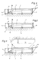
- 1 denotes a container which is carried by a frame 2.
- the frame is rust-like, not shown in detail, i.e. it has a multiplicity of openings through which liquid can pass.
- a collecting funnel 3 Arranged below the frame 2 is a collecting funnel 3, which is connected to a tank 5 via a line 4 with a shut-off valve or shut-off valve.
- the frame 2 has supports 14 which stand on the bottom of a tub 15.
- the tub 15 is made of corrosion-resistant material, for example hot-dip galvanized steel, stainless steel and the like.
- the edges extend to the height of the frame 2.
- the tub can also be made from building materials, such as concrete.
- the trough is preferably designed as a pit.
- the frame 2 is followed by a cover 10, through which there is access to the tub.
- a collecting container 16 and storage container 17 are incorporated into the trough, the outflow of the collecting funnel 3 opening into the collecting container 16.
- a submersible pump is installed in the collecting container 16, which is controlled, for example, by a float and conveys the liquid into the storage container 17, from which the liquid can then be finally disposed of.
- the collecting container 16 or storage container 17 or the tank 5 can also be arranged below the frame 2, so that a short trough 15 can be provided.
- leakage indicators or liquid level indicators are provided in the parking spaces according to the invention, which e.g. trigger an alarm when the tank 5 or the reservoir 17 are filled with liquid.
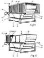
- FIG. 5 The construction of a sliding cover for containers according to the invention can be seen, inter alia, from FIG. 5, in which the section roof 20 consisting of the segments 27, 28, 29 is shown closed.
- the inverted U-shaped segments overlap the outer contour of the container 26 in its upper contour, the filling region 33, and are each guided laterally at rails 30 arranged parallel to the container 26.
- the individual segments are designed to overlap each other, so that in the open state all segments are covered by the largest sectional roof 27 in its external dimensions.
- each segment can be displaced in its own rail 30, the displacement being able to be carried out by an electric motor 24 which can be actuated by means of a switch 23.
- the section roof can be moved by means of a circulating chain, which is arranged, for example, below the rails 30 and into which a driver attached to the segment 27 engages to open or close the section roof 20.
- the section roof can also be moved by hand.
- the motor drive for moving the container cover can also be operated remotely by means of a radio control.
- the motorized displacement of the section roof is coupled with a warning light 25, which gives an optical signal when the container cover is displaced.
- the container 26 shown in FIGS. 5 and 6 is located on a collecting device 32, in which liquids escaping from the container 26 which must not penetrate into the ground are collected.
- a support frame 31 which is U-shaped, partially surrounds the collecting device 32 and is guided to the side of the container 26 up to approximately half its height and serves to accommodate the horizontally arranged rails 30.
- the support frame 31 is open at the end faces to accommodate the container by a transport vehicle.
- FIGS. 7 and 8 an alternative solution to the section roof described above is shown in a side view, which is formed overall from the segments 38-40.
- a side view which is formed overall from the segments 38-40.
- the structure of the section roof 21 provides for a rigid connection between the segments 37, 38, which can be moved together, the segment 37 having an inclined end face 41, by means of which an overhang of the segment 37 is reduced in the lower region and, on the other hand, the extension of the Rail 42 can be narrowed down.
- the embodiment according to FIGS. 7 and 8 also shows a collecting device 44 which is rigidly connected to the supporting frame 43 and which together with the container and its movable cover represent a disposal site which is advantageously not tied to a specific location.
- the container can also be designed as a roll container.
Landscapes
- Engineering & Computer Science (AREA)
- Architecture (AREA)
- Structural Engineering (AREA)
- Mechanical Engineering (AREA)
- Civil Engineering (AREA)
- Electromagnetism (AREA)
- Physics & Mathematics (AREA)
- Thermally Insulated Containers For Foods (AREA)
- Devices For Use In Laboratory Experiments (AREA)
- Glass Compositions (AREA)
- Cultivation Receptacles Or Flower-Pots, Or Pots For Seedlings (AREA)
- Refuse Receptacles (AREA)
- Refuse Collection And Transfer (AREA)
Description
- Die Erfindung bezieht sich auf einen Abstellplatz für Behälter, in denen das Erdreich schädigende Materialien gelagert sind, wobei unterhalb des Behälters eine Auffangeinrichtung mit einem Auffangbehälter und einer Abdeckung vorgesehen ist.
- Ein solcher Abstellplatz für Behälter ist aus der CH-A 543 430 bekannt. Die Abstellvorrichtung weist einen Tank auf, dessen Oberseite als Abstellplatz für Fässer und Behälter ausgebildet ist. Die aus den Fässern oder Behältern austretende Flüssigkeit kann durch eine Öffnung in den Tank fließen. Weiterhin weist der Abstellplatz eine Abdeckung auf, die fest an dem Tank befestigt ist und deren Seitenwände hochklappbar sind. Der gesamte Abstellplatz ist transportabel ausgelegt und eignet sich daher nur zum Abstellen von kleineren Fässern oder Behältern.
- Die Lehre der Druckschrift NL-A 8 800 624 betrifft eine Abdeckeinrichtung für einen Container wobei die Abdeckvorrichtung an auf Fundamenten befestigten Stützen, die seitlich des Containers angeordnet sind, angelenkt ist, und wobei die Abdeckvorrichtung mittels einer Schwenkvorrichtung aufklappbar ist. Durch die Abdeckvorrichtung soll der Container, der im übrigen unmittelbar auf dem neben den Fundamenten anschließenden Boden abgesetzt ist, vor dem Eindringen von Regen in das Containerinnere geschützt werden.
- Aufgabe der vorliegenden Erfindung ist es, einen Abstell- bzw. Entsorgungsplatz für Behälter zur Verfügung zu stellen, der eine Schädigung des Erdreiches durch Eindringen schädlicher Stoffe im Bereich des Abstellplatzes mit Sicherheit verhindert, wobei die Größe der Behälter oder Fässer nicht auf Kleinbehälter oder Kleinfässer beschränkt sein soll.
- Die Aufgabe der Erfindung wird dadurch gelöst, daß der Behälter als Container mit einem oberen Einfüllbereich zur Aufnahme von Teilen, z.B. Schrottspänen, Schrottstanzteilen und dergl. mit daran haftendem Bohröl, ausgebildet ist, daß die Auffangeinrichtung eine Wanne aufweist, daß ein den Container aufnehmendes Gestell vorgesehen ist, daß am Gestell Stützen befestigt sind, die bis zum Boden der Wanne reichen und daß die Abdeckung als hochklappbares Dach oder verschiebbares Dach ausgebildet ist, wobei die Dächer nach Hochklappen oder Verschieben den Einfüllbereich des Containers freigeben.
- Insbesondere im Metall verarbeitenden Gewerbe fallen als Abfallprodukte Späne, Stanzteile und dergl. an. Die Werkzeuge der Bearbeitungsmaschinen werden üblicherweise mit Bohröl gekühlt und geschmiert. Dadurch haftet an den Spänen bzw. Stanzteilen Öl an, das mit dem Schrott in den Container gelangt. Die Container werden je nach betrieblicher Ausstattung auf befestigten Stellen ggfs. Betonflächen abgestellt, wobei jedoch das Problem besteht, das Bohröl, das aus Öffnungen des Containers ausläuft, ins Erdreich gelangt. Selbst wenn die Container, was üblicherweise nicht der Fall ist, dicht ausgeführt wären, ist dies langfristig nicht ausreichend, da im rauhen Betrieb bei der Befüllung der Container mit Schrott sehr schnell Undichtheiten auftreten. Dieser Container wird auf das erfindungsgemäß ausgebildete Gestell abgesetzt und das aus dem Container austretende Bohröl wird in der Wanne aufgefangen. Weiterhin ist die Wanne durch ein den Container aufnehmendes Gestell abgedeckt, das je nach Ausgestaltung der Wanne in einem Absatz derselben bzw. mit Stützen auf dem Boden der Wanne angeordnet ist.
- In vorteilhafter Weise ist die Wanne aus Baumaterialien, z.B. Stahlbeton, hergestellt, wobei die Wanne auf ihrer Innenseite mit einem Dichtmittel, z.B. Epoxydharz versehen ist. Alternativ kann die Wanne aus korrosionsbeständigem Material, z.B. feuerverzinktem Stahl, hergestellt sein. Je nach den örtlichen Gegebenheiten kann es zweckmäßig sein, wenn die Wanne als eine Grube ausgehoben und diese in Beton bzw. Stahlbeton ausgeführt wird. Andererseits kann aber auch, wenn die Bodengegebenheiten dies nicht zulassen, oder auch aus Kostengründen, eine Wanne vorgesehen werden, die auf planiertem bzw. entsprechend vorbereitetem Boden abgestellt wird. Die Wanne kann sich - dies muß jedoch nicht unbedingt der Fall sein - an einer Rampe anschließen, wobei die Oberkante der Wanne etwa der Höhe der Rampe entspricht.
- In Weiterbildung ist das Gestell vorzugsweise rostartig ausgebildet und weist an seiner Unterseite einen Auffangtrichter auf, dessen Mündung mit einem Tank in Verbindung steht. Dadurch werden alle aus dem Container austretenden Flüssigkeiten über den Auffangtrichter in den Tank geleitet und dort aufgefangen. Der Tank ist in vorteilhafter Weise versetzt, vorzugsweise in Längsrichtung des Gestells, angeordnet und mit einer verschließbaren Zusatzöffnung, die sich an das Gestell anschließt, abgedeckt. Dadurch ergibt sich zum einen eine ebene obere Fläche der Grube bzw. der Wanne zum anderen eine gute Zugangsmöglichkeit zum Tank, so daß die dort angesammelte Flüssigkeit, beispielsweise mit einer Pumpe entfernt und entsorgt werden kann. Andererseits ist es auch möglich, die Zuleitung zum Tank zu unterbrechen und den Tank auszuwechseln. In vorteilhafter Weise sitzt der Tank in einer Vertiefung bzw. einem Sumpf, so daß sich in diesem Bereich auch bei Leckagen am Auffangtrichter, der Leitung oder dem Tank alle Flüssigkeiten sammeln, die ihrerseits von der dichten Wanne aufgefangen werden. Dabei können in Verbindung mit der Wanne statt des Tanks eine Auffang- und ein Vorratsbehälter vorgesehen sein, wobei in dem Auffangsbehälter die Flüssigkeit gesammelt und von dort, z.B. mittels einer schwimmergesteuerten Pumpe, in den Vorratsbehälter gefördert wird.
- Wird eine besonders kurze Wanne gewünscht, so können der Auffang- und/oder der Vorratsbehälter und/oder der Tank auch unterhalb des Gestells bzw. Auffangtrichters angeordnet sein, wobei dann eine Reinigungs- oder Zugangsklappe auch seitlich angeordnet sein kann. Je nach Lage der Klappe muß dabei auf Dichtheit geachtet werden.
- In vorteilhafter Weise weist darüberhinaus die Wanne und/oder der Tank eine Leckagewarneinrichtung auf, die eventuelle Undichtheiten anzeigt.
- In weiterer Ausgestaltung der Erfindung sind, um das Eindringen von Regen in den Container zu verhindern, Pfosten, insbesondere auf einer Längsseite des Abstellplatzes, vorgesehen, an denen ein hochklappbares Dach befestigt ist. Das Hochklappen ist deshalb von Bedeutung, weil üblicherweise die Container mittels eines Absetzkippers transportiert werden, der von oben an den Container heranreichende Hubarme aufweist.
- In einer zusätzlichen Ausgestaltung der Erfindung ist als Abdeckung des Containers oder auch eines Lagerplatzes für Altmaterial ein Sektionsdach umgekehrt U-förmig über dem Einfüllbereich des Containers bzw. des Lagerplatzes angebracht. Die einzelnen Segmente sind zueinander überdeckend ausgelegt und stufenweise ein- und ausfahrbar, wobei der beanspruchte Bauraum im eingefahrenen Zustand des Sektionsdaches vorteilhaft nur den Bauraum eines Segmentes erfordert.
- Als eine Alternative zu der bevorzugten Gestaltung der Segmente, bei der eine horizontale Verbildung zwischen den beiden Seitenflächen des Segmentes besteht, kann diese durch zwei übereinstimmend schräggestellte Flächen in Form eines Spitzdaches ersetzt werden.
- Der erfindungsgemäße Aufbau der Abdeckung sieht weiter seitlich horizontal verlaufend angeordnete Schienen vor, die auf bzw. an einem Tragrahmen angeordnet sind und in denen die Segmente längsverschiebbar sind. Vorteilhaft ist jedem Segment eine eigene Schiene zugeordnet, wobei diese in einem parallelem Abstand zueinander angeordnet sind. Neben einer exakten Führung wird weiter durch die beanspruchte Schienen-Anordnung erreicht, daß seitlich am Container herunterfallendes Material beim Befüllen zwischen den Schienen durchfallen kann und ein Verschieben des Sektionsdaches dadurch nicht behindert wird.
- Zur Darstellung einer kostengünstigen Gestaltung der Schienen bietet es sich an, diese durch hochkantig gestellte Flacheisen darzustellen, deren paralleler Abstand beispielsweise durch Abstandshülsen erreichbar ist. Die Schienenmontage wie auch der Austausch einer Schiene wird erleichtert durch eine Verschraubung der einzelnen Schienen jeder Seite zu einer Einheit. Aufgrund des Schienenprofils ist die Gefahr von Verunreinigungen gering, da diese nahezu ungehindert zwischen den Schienen hindurchfallen und weiter sich kein Regenwasser und Schnee im Schienenbereich sammeln kann. Durch Versuche hat sich ein Schienenabstand von ca. 30 mm bewährt, der die Verschiebung des Sektionsdaches in der Praxis gewährleistet.
- Eine weitere Ausgestaltung sieht Profilräder vor, über die die einzelenen Segmente in bzw. auf den Schienen leichtgängig abrollen zur Erreichung einer geringen Antriebsleistung und einer leichten manuellen Verschiebbarkeit des Sektionsdaches.
- Der Aufbau des erfindungsgemäßen Sektionsdaches sieht Anschläge bzw. Mitnehmer in den einzelnen Segmenten vor, durch die eine Kopplung zwischen dem mit einem Antrieb versehenen Segment und den übrigen Segmenten erfolgt, wobei die Verschiebung eines benachbarten Segmentes erst nach Erreichung eines Stellweges erfolgt, der der Längserstreckung des übergreifenden Segmentes entspricht. Aufgrund der ziehenden oder schiebenden Bewegung der einzelnen Segmente sind diese jeweils stirnseitig in Richtung der Längsachse des Sektionsdaches mit Anschlägen versehen.
- Eine einseitige Verlängerung der Schienen erlaubt bei eingefahrenem Sektionsdach die völlige Freilegung des Containers, insbesonderes seines Einfüllbereichs und damit eine optimale Zugänglichkeit. Zur Erreichung einer gewissen Eingrenzung der Schienenverlängerung ist erfindungsgemäß das in Richtung Schienenverlängerung weisende Segment verlängert bzw. mit einem weiteren Segment starr gekoppelt, wobei dieses am freien Ende eine nach innen gerichtete Schräge aufweist zur Eingrenzung des Überstandsmaßes.
- Alle Segmente sind weiter mit einem den Schienenbereich bzw. Tragrahmen hintergreifenden Element, z.B. in Form eines Hebels, auf der zum Container gerichteten Seite versehen, der eine Hinterklammerung darstellt und zum Schutz gegen ein "Entgleisen" sowie zur Windsicherung eines Segmentes eingesetzt sind. Durch eine Verbindung der einzelnen Hebel bzw. der Hinterklammerung in Form einer Blechabdeckung kann darüber hinaus ein wirksamer Schutz der Profilräder und Schienen vor aus dem Container fallenden Material erreicht werden.
- In einer Ausgestaltung der Erfindung ist ein Motorantrieb für die Verschiebung des Sektionsdaches vorgesehen. Zur Erreicherung einer vorteilhaft einfachen Antriebslösung ist ausschließlich das Segment mit dem Antrieb verbunden, welches zur Verschiebung von der geöffneten in die geschlossene Stellung den längsten Stellweg aufweist. Vorzugsweise ist der Antrieb mit einem einseitigen Kettenantrieb versehen, z.B. in Form einer Umlaufkette, in die ein Antriebsritzel eines Elektromotors eingreift. Zur Antriebskopplung zwischen dem Segment und der Umlaufkette bietet es sich an, Bauelemente vorzusehen, wie z.B. ein Klappriegel oder Schwenkhebel, die ein einfaches und schnelles Lösen des Segment-Antriebes erlauben, um bei einem Stromausfall oder einer Störung im Antrieb das Sektionsdach von Hand verschieben zu können. Eine Einbauanordnung der Umlaufkette unterhalb der Schienen bzw. in einem weitestgehend abgedeckten Gehäuse verringert die Unfallgefahr und schützt die Antriebskette gleichzeitig vor Verschmutzung und erhöht folglich die Verfügbarkeit des Antriebes.
- Zum Auslösen des Antriebes dient erfindungsgemäß ein vorzugsweise im Bereich der Schienen oder am Tragrahmen angeordneter Tast- oder Handschalter. Zur Bedienungserleichterung ist weiter eine Funksteuerung vorgesehen, mit der die einzelnen Segmente des Sektionsdaches durch Fernbetätigung verfahrbar sind, was insbesondere für eine Beschickung der Container mittels Gabelstapler vorteilhaft ist und eine Zeitersparnis bewirkt. Außerdem kann die erfindungsgemäße verschiebbare Containerabdeckung gekoppelt werden mit einer selbsttätigen Containerbeschickung. Durch eine Steuerung, mit der sichergestellt ist, daß die Beschickung erst dann erfolgen kann, wenn das Sektionsdach entsprechend geöffnet ist, kann auf einen manuellen Eingriff verzichtet werden.
- Zur weiteren Erläuterung der Erfindung wird auf die Zeichnungen verwiesen, in denen Ausführungsbeispiele der Erfindung vereinfacht dargestellt sind.
Es zeigen: - Fig. 1 bis 4a
- einen Abstellplatz für Container in Längs- und Querschnitten, bei dem eine Wanne vorgesehen ist,
- Fig. 5
- ein Sektionsdach mit Container in der Perspektive, dargestellt in geschlossener Stellung, bestehend aus drei Segmenten,
- Fig. 6
- eine Darstellung gemäß Fig. 5, bei der das Segmentdach geöffnet ist,
- Fig. 7
- eine aus vier Segmenten bestehende geschlossene Container-Abdeckung in einer Seitenansicht,
- Fig. 8
- die Container-Abdeckung gemäß Fig. 3 in der geöffneten Stellung.
- In den Fig. 1 bis 4a sind, soweit im einzelnen dargestellt, mit 1 ein Container bezeichnet, der von einem Gestell 2 getragen wird. Das Gestell ist, im einzelnen nicht dargestellt, rostartig ausgebildet, d.h. es hat eine Vielzahl von Öffnungen, durch die Flüssigkeit hindurchtreten kann. Unterhalb des Gestells 2 ist ein Auffangtrichter 3 angordnet, der über eine Leitung 4 mit einem Absperrhahn oder Absperrventil mit einem Tank 5 verbunden ist.
- Das Gestell 2 weist Stützen 14 auf, die auf dem Boden einer Wanne 15 stehen. Die Wanne 15 ist aus korrosionsbeständigem Material, z.B. feuerverzinktem Stahl, rostfreiem Stahl und dergl. hergestellt, wobei die Ränder bis zur Höhe des Gestells 2 reichen. Alternativ kann die Wanne aber auch aus Baumaterialien, z.B. Beton hergestellt sein. In diesem Fall ist die Wanne vorzugsweise als Grube ausgebildet. An das Gestell 2 schließt sich ein Deckel 10 an, durch den ein Zugang in die Wanne gegeben ist. In dem Ausführungsbeispiel gemäß den Fig. 1 bis 4a sind in die Wanne ein Auffangbehälter 16 und Vorratsbehälter 17 eingearbeitet, wobei der Abfluß des Auffangtrichters 3 in den Auffangbehälter 16 mündet. In dem Auffangbehälter 16 ist eine Tauchpumpe installiert, die beispielsweise über einen Schwimmer gesteuert ist und die Flüssigkeit in den Vorratsbehälter 17 fördert, aus dem dann eine endgültige Entsorgung der Flüssigkeit erfolgen kann.
- Wie bereits angesprochen, können der Auffang- 16 bzw. Vorratsbehälter 17 oder der Tank 5 auch unterhalb des Gestells 2 angeordnet sein, so daß eine kurze Wanne 15 vorgesehen sein kann.
- Wie bereits in der allgemeinen Beschreibung ausgeführt, sind bei den erfindungsgemäßen Abstellplätzen Leckageanzeigen bzw. Flüssigkeitsstandsanzeigen vorgesehen, die z.B. einen Alarm auslösen, wenn der Tank 5 bzw. der Vorratsbehälter 17 mit Flüssigkeit angefüllt sind.
- Der erfindungsgemäße Aufbau einer verschiebbaren Abdeckung für Container ist u.a. der Fig. 5 zu entnehmen, bei der das aus den Segmenten 27, 28, 29 bestehende Sektionsdach 20 geschlossen dargestellt ist. Die umgekehrt U-förmig gestalteten Segmente übergreifen die Außenkontur des Containers 26 in seiner oberen Kontur, den Einfüllbereich 33, und sind jeweils seitlich im parallelen Abstand zum Container 26 angeordneten Schienen 30 geführt. Zur Erreichung einer verschiebbaren Abdeckung, die in der geöffneten Stellung wenig Platz beansprucht, sind die einzelnen Segmente zueinander übergreifend ausgelegt, so daß im geöffneten Zustand alle Segmente von dem in seinen Außenabmessungen größten Sektionsdach 27 überdeckt sind. Zur Erreichung einer exakten Längsverschiebung ist jedes Segment in einer eigenen Schiene 30 verschiebbar, wobei die Verschiebung durch einen Elektromotor 24 erfolgen kann, der mittels eines Schalters 23 betätigbar ist. Die Verschiebung des Sektionsdaches kann durch eine Umlaufkette erfolgen, die beispielsweise unterhalb der Schienen 30 angeordnet ist und in die ein am Segment 27 befestigter Mitnehmer greift zum Öffnen oder Schließen des Sektionsdaches 20. Alternativ zum Motorantrieb ist das Sektionsdach auch von Hand verschiebbar. Zur vereinfachten Beschickung des Containers ist der Motorantrieb zur Verschiebung der Container-Abdeckung auch mittels einer Funksteuerung fernbetätigbar. Aus Sicherheitsgründen ist die motorbetriebene Verschiebung des Sektionsdaches gekoppelt mit einer Warnleuchte 25, die ein optisches Signal gibt bei einer Verschiebung der Container-Abdeckung. Der in den Figuren 5 und 6 dargestellte Container 26 befindet sich auf einer Auffangvorrichtung 32, in der aus dem Container 26 austretende Flüssigkeiten, die nicht ins Erdreich dringen dürfen, aufgefangen werden. Ein Tragrahmen 31, der U-förmig ausgebildet ist, umschließt teilweise die Auffangsvorrichtung 32 und ist seitlich des Containers 26 bis ungefähr zu dessen halber Höhe geführt und dient zur Aufnahme der horizontal angeordneten Schienen 30. An den Stirnseiten ist der Tragrahmen 31 offen gestaltet zur Containeraufnahme durch ein Transportfahrzeug.
- Aus den Fig. 7 und 8 ist in einer Seitenansicht eine Alternativlösung zu dem zuvor beschriebenen Sektionsdach dargestellt, das insgesamt aus den Segmenten 38 - 40 gebildet ist. Zur Verlängerung des Stellweges vom Sektionsdach 21 ist es in der geöffneten Stellung aufgrund einseitig verlängerter Schienen 42 so weit verschiebbar, daß der Container 36 über den gesamten Einfüllbereich 45 befüllbar ist. Der Aufbau des Sektionsdaches 21 sieht dazu eine starre Verbindung zwischen den Segmenten 37, 38 vor, die gemeinsam verschiebbar sind, wobei das Segment 37 eine schrägverlaufende Stirnseite 41 aufweist, durch die ein Überhang des Segmentes 37 im unteren Bereich verringert ist und andererseits die Verlängerung der Schiene 42 eingegrenzt werden kann. Wie bereits im zuvor beschriebenen Ausführungsbeispiel zeigt auch die Ausführung gemäß den Fig. 7 und 8 eine Auffangsvorrichtung 44, die starr mit dem Tragrahmen 43 verbunden ist und die gemeinsam mit dem Container und dessen verschiebbarer Abdeckung einen Entsorgungsplatz darstellen, der vorteilhaft nicht standortgebunden ist. Der Container kann im übrigen auch als Rollcontainer ausgebildet sein.
Claims (12)
- Abstellplatz für Behälter, in denen das Erdreich schädigende Materialien gelagert sind, wobei unterhalb des Behälters eine Auffangeinrichtung mit einem Auffangbehälter und einer Abdeckung vorgesehen ist, wobei die Auffangeinrichtung eine Wanne (15, 32, 44) aufweist, und ein den Behälter (1, 26, 36, 46) aufnehmendes Gestell (2) vorgesehen ist,
dadurch gekennzeichnet,- daß der Behälter als Container (1, 26, 36, 46) mit einem oberen Einfüllbereich zur Aufnahme von Teilen z.B. Schrottspänen, Schrottstanzteilen und dergl. mit daran haftendem Bohröl, ausgebildet ist,- daß am Gestell (2) Stützen (14) befestigt sind, die bis zum Boden der Wanne (15, 32, 44) reichen und- daß die Abdeckung als hochklappbares Dach (12) oder verschiebbares Dach (20, 21, 22) ausgebildet ist, wobei die Dächer (12, 20, 21, 22) nach Hochklappen oder Verschieben den Einfüllbereich (33, 45, 55) des Containers (1, 26, 36, 46) freigeben. - Abstellplatz für Behälter nach Anspruch 1,
dadurch gekennzeichnet, daß die Wanne (15, 32, 44) aus Baumaterialien, z.B. Beton, hergestellt ist, wobei die Wanne (15, 32, 44) auf ihrer Innenseite mit einem Dichtmittel, z.B. Epoxydharz, versehen ist. - Abstellplatz für Behälter nach Anspruch 1,
dadurch gekennzeichnet, daß die Wanne (15, 32, 44) aus korrosionsbeständigem Material, z.B. feuerverzinktem Stahl, hergestellt ist. - Abstellplatz für Behälter nach einem der vorhergehenden Ansprüche,
dadurch gekennzeichnet, daß das Gestell (2) rostartig ausgebildet ist und daß die unterhalb des Gestells (2) angeordnete Auffangvorrichtung einen Auffangtrichter (3) aufweist, dessen Mündung mit einem Auffangbehälter (16) bzw. Vorratsbehälter (17) oder einem Tank (5) in Verbindung steht. - Abstellplatz für Behälter nach einem der vorhergehenden Ansprüche,
dadurch gekennzeichnet, daß der Auffangbehälter (16) bzw. Vorratsbehälter (17) oder der Tank (5) versetzt, vorzugsweise in Längsrichtung des Gestells (2) angeordnet sind und daß oberhalb des Auffangbehälters (16) bzw. Vorratsbehälters (17) oder des Tanks (5) und neben dem Gestell (2) eine verschließbare Zugangsöffnung (9) vorgesehen ist. - Abstellplatz für Behälter nach einem der vorhergehenden Ansprüche,
dadurch gekennzeichnet, daß in der Wanne (15, 32, 44) und/oder in den Behältern (16 bzw. 17) oder dem Tank (5) Pumpen und/oder Leckagewarneinrichtungen und/oder Flüssigkeitsstandsanzeigen vorgesehen sind. - Abstellplatz für Behälter nach einem der vorhergehenden Ansprüche,
dadurch gekennzeichnet, daß neben bzw. an der Wanne (15, 32, 44) oder dem Gestell (2) Pfosten (11) angeordnet sind, an denen ein hochklappbares Dach (12) befestigt ist. - Abstellplatz für Behälter nach einem der vorhergehenden Ansprüche,
dadurch gekennzeichnet, daß zumindest an einer Seite des Gestells (2) nach außen ragende Auffangbleche (18) befestigt sind, die Gefälle in Richtung des Gestells (2) haben. - Abstellplatz für Behälter nach einem der vorhergehenden Ansprüche
oder Lagerplatz für Altmaterialien zum Schutz vor Witterungseinflüssen, dadurch gekennzeichnet, daß als Abdeckung ein vorzugsweise U-förmig gestaltetes Sektionsdach (20, 21, 22), in der Größe angepaßt an die abzudeckenden Gegenstände, vorgesehen ist, das mehrere ineinander verschiebbare Segmente (27-29, 38-40, 47-51), die den gesamten Einfüllbereich (33, 45, 55) des Containers (26, 36, 46) überdecken, aufweist, und daß die einzelnen Segmente jeweils zueinander überdeckend ausgelegt und stufenweise ein- und ausfahrbar sind. - Abstellplatz für Behälter nach einem der vorhergehenden Ansprüche,
dadurch gekennzeichnet, daß die Segmente (27-29, 38-40, 47-51) des Sektionsdaches (20, 21, 22) in seitlich des Containers (26, 36, 46) verlaufenden Schienen (30, 42, 52) längsverschiebbar sind, daß die Schienen (30, 42, 52) auf einem Tragrahmen (31, 43, 53) angeordnet sind und daß jedem Segment eine Schiene beidseits des Containers zugeordnet ist, wobei die Schienen durch hochkantig gestellte Flacheisen gebildet sind, die mittels Abstandshülsen parallel zueinander gehalten und durch Befestigungselemente zu einer Einheit zusammengefügt sind. - Abstellplatz für Behälter nach einem der vorhergehenden Ansprüche,
dadurch gekennzeichnet, daß jedes Segment (27-29, 38-40, 47-51) mit einem die Schienen (30, 42, 52) hintergreifenden Element versehen ist. - Abstellplatz für Behälter nach einem der vorhergehenden Ansprüche,
dadurch gekennzeichnet, daß die Segmente (27-29, 38-40, 47-51) des Sektionsdaches (20, 21, 22) motorbetrieben sind, daß ein einseitiger Kettenantrieb für das mit dem Antrieb verbundene, den längsten Stellweg aufweisende Segment vorgesehen ist, daß der Antrieb durch einen Tast- bzw. Handschalter auslösbar ist und daß der Antrieb durch eine Funksteuerung betätigbar ist.
Applications Claiming Priority (4)
| Application Number | Priority Date | Filing Date | Title |
|---|---|---|---|
| DE19893937822 DE3937822A1 (de) | 1989-11-14 | 1989-11-14 | Abstellplatz fuer container |
| DE3937822 | 1989-11-14 | ||
| DE9013372U | 1990-09-21 | ||
| DE9013372U DE9013372U1 (de) | 1990-09-21 | 1990-09-21 |
Publications (2)
| Publication Number | Publication Date |
|---|---|
| EP0428113A1 EP0428113A1 (de) | 1991-05-22 |
| EP0428113B1 true EP0428113B1 (de) | 1994-03-30 |
Family
ID=25887045
Family Applications (1)
| Application Number | Title | Priority Date | Filing Date |
|---|---|---|---|
| EP90121642A Revoked EP0428113B1 (de) | 1989-11-14 | 1990-11-12 | Abstellplatz für Container |
Country Status (4)
| Country | Link |
|---|---|
| EP (1) | EP0428113B1 (de) |
| AT (1) | ATE103565T1 (de) |
| DE (2) | DE9018063U1 (de) |
| DK (1) | DK0428113T3 (de) |
Cited By (15)
| Publication number | Priority date | Publication date | Assignee | Title |
|---|---|---|---|---|
| US8126601B2 (en) | 2006-03-20 | 2012-02-28 | General Electric Company | System and method for predicting a vehicle route using a route network database |
| US8234023B2 (en) | 2009-06-12 | 2012-07-31 | General Electric Company | System and method for regulating speed, power or position of a powered vehicle |
| US8249763B2 (en) | 2006-03-20 | 2012-08-21 | General Electric Company | Method and computer software code for uncoupling power control of a distributed powered system from coupled power settings |
| US8290645B2 (en) | 2006-03-20 | 2012-10-16 | General Electric Company | Method and computer software code for determining a mission plan for a powered system when a desired mission parameter appears unobtainable |
| US8370007B2 (en) | 2006-03-20 | 2013-02-05 | General Electric Company | Method and computer software code for determining when to permit a speed control system to control a powered system |
| US8370006B2 (en) | 2006-03-20 | 2013-02-05 | General Electric Company | Method and apparatus for optimizing a train trip using signal information |
| US8401720B2 (en) | 2006-03-20 | 2013-03-19 | General Electric Company | System, method, and computer software code for detecting a physical defect along a mission route |
| US8473127B2 (en) | 2006-03-20 | 2013-06-25 | General Electric Company | System, method and computer software code for optimizing train operations considering rail car parameters |
| US8768543B2 (en) | 2006-03-20 | 2014-07-01 | General Electric Company | Method, system and computer software code for trip optimization with train/track database augmentation |
| US8788135B2 (en) | 2006-03-20 | 2014-07-22 | General Electric Company | System, method, and computer software code for providing real time optimization of a mission plan for a powered system |
| US8924049B2 (en) | 2003-01-06 | 2014-12-30 | General Electric Company | System and method for controlling movement of vehicles |
| US9201409B2 (en) | 2006-03-20 | 2015-12-01 | General Electric Company | Fuel management system and method |
| US9233696B2 (en) | 2006-03-20 | 2016-01-12 | General Electric Company | Trip optimizer method, system and computer software code for operating a railroad train to minimize wheel and track wear |
| US9266542B2 (en) | 2006-03-20 | 2016-02-23 | General Electric Company | System and method for optimized fuel efficiency and emission output of a diesel powered system |
| US9527518B2 (en) | 2006-03-20 | 2016-12-27 | General Electric Company | System, method and computer software code for controlling a powered system and operational information used in a mission by the powered system |
Families Citing this family (12)
| Publication number | Priority date | Publication date | Assignee | Title |
|---|---|---|---|---|
| DE9103622U1 (de) * | 1990-05-30 | 1991-09-26 | Schneider Werk St. Wendel Gmbh & Co. Kg, 6690 St Wendel, De | |
| DE4119961A1 (de) * | 1991-06-18 | 1992-12-24 | Manfred Sirch | Schlammlager- und transportbehaelter |
| DE4134010A1 (de) * | 1991-10-14 | 1993-04-15 | R & Th Blass Gmbh | Stellplatz fuer abfallcontainer |
| EP0750576B1 (de) * | 1994-03-15 | 1998-06-03 | H.J. Hansen Mijosystem A/S | Verfahren und bauteil zur bildung von provisorischen lagersystemen für leckfähige behälter mit gefährlichen flüssigkeiten |
| DE19722621A1 (de) * | 1997-05-30 | 1998-12-03 | Aeg Energietechnik Gmbh | Mobile Tragvorrichtung für Geräte mit umweltschädlichen Flüssigkeiten |
| FR2832989B1 (fr) * | 2001-12-03 | 2004-02-20 | Lucas Sa G | Abri pour benne de recuperation de dechets |
| US9733625B2 (en) | 2006-03-20 | 2017-08-15 | General Electric Company | Trip optimization system and method for a train |
| DE10337422A1 (de) * | 2003-08-14 | 2005-03-10 | Bsh Bosch Siemens Hausgeraete | Abfallsammelvorrichtung mit Reinigungsanlage |
| US9156477B2 (en) | 2006-03-20 | 2015-10-13 | General Electric Company | Control system and method for remotely isolating powered units in a vehicle system |
| US8373289B2 (en) | 2007-09-06 | 2013-02-12 | F3 & I2, Llc | Energy generating modules with fuel chambers |
| CN101796681B (zh) | 2007-09-06 | 2013-02-13 | F3&I2有限责任公司 | 带有燃料室的能量产生模块 |
| US8235009B2 (en) | 2009-02-03 | 2012-08-07 | F3 & I2, Llc | Energy generating modules with exterior wall fuel chambers |
Family Cites Families (6)
| Publication number | Priority date | Publication date | Assignee | Title |
|---|---|---|---|---|
| CH543430A (de) * | 1972-09-01 | 1973-10-31 | Edgar Steck Ferdinand | Lagervorrichtung für Behälter, die umweltgefährliche Flüssigkeiten enthalten |
| DE3612856A1 (de) * | 1986-04-16 | 1987-10-22 | Hans Juergen Dipl Ing Meyer | Tiefbunker |
| DE3739125A1 (de) * | 1987-11-19 | 1989-06-01 | Gewerk Keramchemie | Chemisch bestaendiger, fluessigkeitsdichter belag |
| NL8800624A (nl) * | 1988-03-15 | 1989-10-02 | Hydrowa B V | Inrichting voor het afdekken van een aan de bovenzijde open bak. |
| DE3937822A1 (de) * | 1989-11-14 | 1991-05-16 | Joerg Kreuzer | Abstellplatz fuer container |
| DE9006084U1 (de) * | 1990-05-30 | 1990-08-02 | Schneider Werk St. Wendel Maschinenfabrik Stahlbau Inh. Bernhard Schneider Ing., 6690 St Wendel, De |
-
1990
- 1990-11-12 DK DK90121642.4T patent/DK0428113T3/da active
- 1990-11-12 EP EP90121642A patent/EP0428113B1/de not_active Revoked
- 1990-11-12 AT AT90121642T patent/ATE103565T1/de not_active IP Right Cessation
- 1990-11-12 DE DE9018063U patent/DE9018063U1/de not_active Expired - Lifetime
- 1990-11-12 DE DE90121642T patent/DE59005184D1/de not_active Revoked
Cited By (18)
| Publication number | Priority date | Publication date | Assignee | Title |
|---|---|---|---|---|
| US8924049B2 (en) | 2003-01-06 | 2014-12-30 | General Electric Company | System and method for controlling movement of vehicles |
| US8725326B2 (en) | 2006-03-20 | 2014-05-13 | General Electric Company | System and method for predicting a vehicle route using a route network database |
| US8370006B2 (en) | 2006-03-20 | 2013-02-05 | General Electric Company | Method and apparatus for optimizing a train trip using signal information |
| US8751073B2 (en) | 2006-03-20 | 2014-06-10 | General Electric Company | Method and apparatus for optimizing a train trip using signal information |
| US8370007B2 (en) | 2006-03-20 | 2013-02-05 | General Electric Company | Method and computer software code for determining when to permit a speed control system to control a powered system |
| US8768543B2 (en) | 2006-03-20 | 2014-07-01 | General Electric Company | Method, system and computer software code for trip optimization with train/track database augmentation |
| US8401720B2 (en) | 2006-03-20 | 2013-03-19 | General Electric Company | System, method, and computer software code for detecting a physical defect along a mission route |
| US8473127B2 (en) | 2006-03-20 | 2013-06-25 | General Electric Company | System, method and computer software code for optimizing train operations considering rail car parameters |
| US8788135B2 (en) | 2006-03-20 | 2014-07-22 | General Electric Company | System, method, and computer software code for providing real time optimization of a mission plan for a powered system |
| US8290645B2 (en) | 2006-03-20 | 2012-10-16 | General Electric Company | Method and computer software code for determining a mission plan for a powered system when a desired mission parameter appears unobtainable |
| US8249763B2 (en) | 2006-03-20 | 2012-08-21 | General Electric Company | Method and computer software code for uncoupling power control of a distributed powered system from coupled power settings |
| US8126601B2 (en) | 2006-03-20 | 2012-02-28 | General Electric Company | System and method for predicting a vehicle route using a route network database |
| US8903573B2 (en) | 2006-03-20 | 2014-12-02 | General Electric Company | Method and computer software code for determining a mission plan for a powered system when a desired mission parameter appears unobtainable |
| US9527518B2 (en) | 2006-03-20 | 2016-12-27 | General Electric Company | System, method and computer software code for controlling a powered system and operational information used in a mission by the powered system |
| US9201409B2 (en) | 2006-03-20 | 2015-12-01 | General Electric Company | Fuel management system and method |
| US9233696B2 (en) | 2006-03-20 | 2016-01-12 | General Electric Company | Trip optimizer method, system and computer software code for operating a railroad train to minimize wheel and track wear |
| US9266542B2 (en) | 2006-03-20 | 2016-02-23 | General Electric Company | System and method for optimized fuel efficiency and emission output of a diesel powered system |
| US8234023B2 (en) | 2009-06-12 | 2012-07-31 | General Electric Company | System and method for regulating speed, power or position of a powered vehicle |
Also Published As
| Publication number | Publication date |
|---|---|
| DE9018063U1 (de) | 1994-10-20 |
| ATE103565T1 (de) | 1994-04-15 |
| EP0428113A1 (de) | 1991-05-22 |
| DE59005184D1 (de) | 1994-05-05 |
| DK0428113T3 (da) | 1994-08-08 |
Similar Documents
| Publication | Publication Date | Title |
|---|---|---|
| EP0428113B1 (de) | Abstellplatz für Container | |
| EP0243316A1 (de) | Verladeanlage mit Müllsilos | |
| DE19829156A1 (de) | Speichereinrichtung für Sammelbehälter | |
| WO2005002994A1 (de) | Anlage für das differenzierte und undifferenzierte sammeln von hausmüll | |
| DE3937822A1 (de) | Abstellplatz fuer container | |
| EP2006221B1 (de) | Unterflursammelbehälter | |
| EP0509422B1 (de) | Einrichtung zur Steuerung von Überfallmengen und Wasserspiegellagen in Wasseranlagen | |
| DE3115477C2 (de) | Fünfseitig geschlossene Raumzelle, insbesondere Aufnahmebox für Müllsammelgefäße | |
| DE3020744C2 (de) | Abdeckung für Großbehälter und Becken | |
| EP0272529B1 (de) | Lager mit Auffangvolumen für Flüssigkeiten | |
| DE2102056A1 (de) | Wasch- und Desinfektionsanlage für Müllbehälter | |
| DE602005006356T2 (de) | Transportable Mülldeponie | |
| DE3142873A1 (de) | Vorrichtung zum abdecken von fluessigkeit enthaltenden becken | |
| CH632799A5 (en) | Double-storey garage | |
| EP0841436B1 (de) | Hochwasserschutzwand | |
| EP0179168A1 (de) | Reparaturhilfseinrichtung | |
| DE202017000723U1 (de) | Vorrichtung zur Übergabe, Entwässerung und Entsorgung von Kehr- und Schüttgut | |
| DE19642989A1 (de) | Abdeckung | |
| DE202011001831U1 (de) | Hubeinrichtung für Gegenstände sowie Gebäude mit einer derartigen Hubeinrichtung | |
| EP0498057B1 (de) | Erweiterbares Lager für schädliche brennbare Flüssigkeiten | |
| DE4321914A1 (de) | Vorrichtung zur Unterbringung von Fahrzeugen | |
| EP0491122A2 (de) | Müllpresse | |
| DE102015202267B4 (de) | Betriebsmittel-Abfüllplatz | |
| DE2927397A1 (de) | Ueberdachte mehretagen-hubgarage | |
| DE102015000828B4 (de) | Sammelbehälter und Sammeleinrichtung für Rest-und/oder Wertstoffe |
Legal Events
| Date | Code | Title | Description |
|---|---|---|---|
| PUAI | Public reference made under article 153(3) epc to a published international application that has entered the european phase |
Free format text: ORIGINAL CODE: 0009012 |
|
| AK | Designated contracting states |
Kind code of ref document: A1 Designated state(s): AT BE CH DE DK FR GB IT LI NL SE |
|
| 17P | Request for examination filed |
Effective date: 19911114 |
|
| 17Q | First examination report despatched |
Effective date: 19921203 |
|
| GRAA | (expected) grant |
Free format text: ORIGINAL CODE: 0009210 |
|
| AK | Designated contracting states |
Kind code of ref document: B1 Designated state(s): AT BE CH DE DK FR GB IT LI NL SE |
|
| REF | Corresponds to: |
Ref document number: 103565 Country of ref document: AT Date of ref document: 19940415 Kind code of ref document: T |
|
| REF | Corresponds to: |
Ref document number: 59005184 Country of ref document: DE Date of ref document: 19940505 |
|
| ET | Fr: translation filed | ||
| ITF | It: translation for a ep patent filed |
Owner name: ING. C. GREGORJ S.P.A. |
|
| PLBI | Opposition filed |
Free format text: ORIGINAL CODE: 0009260 |
|
| GBT | Gb: translation of ep patent filed (gb section 77(6)(a)/1977) |
Effective date: 19940705 |
|
| REG | Reference to a national code |
Ref country code: DK Ref legal event code: T3 |
|
| 26 | Opposition filed |
Opponent name: S-KON R. BERTELS GMBH Effective date: 19940702 |
|
| NLR1 | Nl: opposition has been filed with the epo |
Opponent name: S-KON R. BERTELS GMBH. |
|
| PLBI | Opposition filed |
Free format text: ORIGINAL CODE: 0009260 |
|
| PLBI | Opposition filed |
Free format text: ORIGINAL CODE: 0009260 |
|
| EAL | Se: european patent in force in sweden |
Ref document number: 90121642.4 |
|
| 26 | Opposition filed |
Opponent name: SCHNEIDER WERK ST. WENDEL GMBH & CO. KG Effective date: 19941222 Opponent name: S-KON R. BERTELS GMBH Effective date: 19940702 |
|
| 26 | Opposition filed |
Opponent name: R. & TH. BLASS GMBH Effective date: 19941229 Opponent name: SCHNEIDER WERK ST. WENDEL GMBH & CO. KG Effective date: 19941222 Opponent name: S-KON R. BERTELS GMBH Effective date: 19940702 |
|
| NLR1 | Nl: opposition has been filed with the epo |
Opponent name: SCHNEIDER WERK ST. WENDEL GMBH & CO. KG |
|
| NLR1 | Nl: opposition has been filed with the epo |
Opponent name: R & TH BLASS GMBH |
|
| PLAW | Interlocutory decision in opposition |
Free format text: ORIGINAL CODE: EPIDOS IDOP |
|
| APAC | Appeal dossier modified |
Free format text: ORIGINAL CODE: EPIDOS NOAPO |
|
| APAE | Appeal reference modified |
Free format text: ORIGINAL CODE: EPIDOS REFNO |
|
| APAC | Appeal dossier modified |
Free format text: ORIGINAL CODE: EPIDOS NOAPO |
|
| PGFP | Annual fee paid to national office [announced via postgrant information from national office to epo] |
Ref country code: DK Payment date: 19981117 Year of fee payment: 9 |
|
| PGFP | Annual fee paid to national office [announced via postgrant information from national office to epo] |
Ref country code: AT Payment date: 19981118 Year of fee payment: 9 |
|
| PGFP | Annual fee paid to national office [announced via postgrant information from national office to epo] |
Ref country code: SE Payment date: 19981119 Year of fee payment: 9 Ref country code: BE Payment date: 19981119 Year of fee payment: 9 |
|
| PGFP | Annual fee paid to national office [announced via postgrant information from national office to epo] |
Ref country code: GB Payment date: 19981120 Year of fee payment: 9 |
|
| PGFP | Annual fee paid to national office [announced via postgrant information from national office to epo] |
Ref country code: DE Payment date: 19981124 Year of fee payment: 9 |
|
| PGFP | Annual fee paid to national office [announced via postgrant information from national office to epo] |
Ref country code: NL Payment date: 19981130 Year of fee payment: 9 Ref country code: FR Payment date: 19981130 Year of fee payment: 9 |
|
| PGFP | Annual fee paid to national office [announced via postgrant information from national office to epo] |
Ref country code: CH Payment date: 19990223 Year of fee payment: 9 |
|
| PG25 | Lapsed in a contracting state [announced via postgrant information from national office to epo] |
Ref country code: GB Free format text: LAPSE BECAUSE OF NON-PAYMENT OF DUE FEES Effective date: 19991112 Ref country code: AT Free format text: LAPSE BECAUSE OF NON-PAYMENT OF DUE FEES Effective date: 19991112 |
|
| PG25 | Lapsed in a contracting state [announced via postgrant information from national office to epo] |
Ref country code: SE Free format text: LAPSE BECAUSE OF NON-PAYMENT OF DUE FEES Effective date: 19991113 |
|
| PG25 | Lapsed in a contracting state [announced via postgrant information from national office to epo] |
Ref country code: LI Free format text: LAPSE BECAUSE OF NON-PAYMENT OF DUE FEES Effective date: 19991130 Ref country code: DK Free format text: LAPSE BECAUSE OF NON-PAYMENT OF DUE FEES Effective date: 19991130 Ref country code: CH Free format text: LAPSE BECAUSE OF NON-PAYMENT OF DUE FEES Effective date: 19991130 Ref country code: BE Free format text: LAPSE BECAUSE OF NON-PAYMENT OF DUE FEES Effective date: 19991130 |
|
| BERE | Be: lapsed |
Owner name: SISTIG KURT Effective date: 19991130 Owner name: KREUZER JORG Effective date: 19991130 |
|
| PG25 | Lapsed in a contracting state [announced via postgrant information from national office to epo] |
Ref country code: NL Free format text: LAPSE BECAUSE OF NON-PAYMENT OF DUE FEES Effective date: 20000601 |
|
| GBPC | Gb: european patent ceased through non-payment of renewal fee |
Effective date: 19991112 |
|
| REG | Reference to a national code |
Ref country code: CH Ref legal event code: PL |
|
| EUG | Se: european patent has lapsed |
Ref document number: 90121642.4 |
|
| NLV4 | Nl: lapsed or anulled due to non-payment of the annual fee |
Effective date: 20000601 |
|
| APAC | Appeal dossier modified |
Free format text: ORIGINAL CODE: EPIDOS NOAPO |
|
| RDAH | Patent revoked |
Free format text: ORIGINAL CODE: EPIDOS REVO |
|
| RDAG | Patent revoked |
Free format text: ORIGINAL CODE: 0009271 |
|
| REG | Reference to a national code |
Ref country code: FR Ref legal event code: ST |
|
| STAA | Information on the status of an ep patent application or granted ep patent |
Free format text: STATUS: PATENT REVOKED |
|
| 27W | Patent revoked |
Effective date: 20000608 |
|
| REG | Reference to a national code |
Ref country code: DK Ref legal event code: EBP |
|
| APAH | Appeal reference modified |
Free format text: ORIGINAL CODE: EPIDOSCREFNO |