EP0423475A1 - Absaug-Regeneriervorrichtung für ein Tintenstrahlaufzeichnungsgerät - Google Patents
Absaug-Regeneriervorrichtung für ein Tintenstrahlaufzeichnungsgerät Download PDFInfo
- Publication number
- EP0423475A1 EP0423475A1 EP90116655A EP90116655A EP0423475A1 EP 0423475 A1 EP0423475 A1 EP 0423475A1 EP 90116655 A EP90116655 A EP 90116655A EP 90116655 A EP90116655 A EP 90116655A EP 0423475 A1 EP0423475 A1 EP 0423475A1
- Authority
- EP
- European Patent Office
- Prior art keywords
- cap
- rail
- carriage
- recovery device
- release valve
- Prior art date
- Legal status (The legal status is an assumption and is not a legal conclusion. Google has not performed a legal analysis and makes no representation as to the accuracy of the status listed.)
- Granted
Links
- 238000011084 recovery Methods 0.000 title claims abstract description 71
- 239000012298 atmosphere Substances 0.000 claims abstract description 124
- 239000007788 liquid Substances 0.000 claims abstract description 17
- 239000000463 material Substances 0.000 claims description 14
- 238000007639 printing Methods 0.000 claims description 7
- 230000003111 delayed effect Effects 0.000 claims description 6
- 239000013013 elastic material Substances 0.000 claims description 4
- 238000010276 construction Methods 0.000 description 19
- 238000004891 communication Methods 0.000 description 10
- 230000000694 effects Effects 0.000 description 8
- 230000000630 rising effect Effects 0.000 description 8
- 230000005540 biological transmission Effects 0.000 description 5
- 238000000034 method Methods 0.000 description 5
- 238000003825 pressing Methods 0.000 description 5
- 239000002699 waste material Substances 0.000 description 5
- 238000007789 sealing Methods 0.000 description 4
- RTZKZFJDLAIYFH-UHFFFAOYSA-N Diethyl ether Chemical compound CCOCC RTZKZFJDLAIYFH-UHFFFAOYSA-N 0.000 description 2
- 239000000428 dust Substances 0.000 description 2
- 229920001971 elastomer Polymers 0.000 description 2
- 239000012535 impurity Substances 0.000 description 2
- 239000004033 plastic Substances 0.000 description 2
- 229920003023 plastic Polymers 0.000 description 2
- 230000003252 repetitive effect Effects 0.000 description 2
- 230000006378 damage Effects 0.000 description 1
- 230000003247 decreasing effect Effects 0.000 description 1
- 230000000881 depressing effect Effects 0.000 description 1
- 230000000994 depressogenic effect Effects 0.000 description 1
- 238000007599 discharging Methods 0.000 description 1
- 238000006073 displacement reaction Methods 0.000 description 1
- 230000008020 evaporation Effects 0.000 description 1
- 238000001704 evaporation Methods 0.000 description 1
- 230000005484 gravity Effects 0.000 description 1
- 239000000976 ink Substances 0.000 description 1
- 238000004519 manufacturing process Methods 0.000 description 1
- 230000005499 meniscus Effects 0.000 description 1
- 229920002635 polyurethane Polymers 0.000 description 1
- 239000004814 polyurethane Substances 0.000 description 1
- 239000011148 porous material Substances 0.000 description 1
- 239000000843 powder Substances 0.000 description 1
- 230000001105 regulatory effect Effects 0.000 description 1
- 238000009877 rendering Methods 0.000 description 1
- 239000012858 resilient material Substances 0.000 description 1
- 229920002379 silicone rubber Polymers 0.000 description 1
- 239000004945 silicone rubber Substances 0.000 description 1
- 239000007787 solid Substances 0.000 description 1
- 229910001220 stainless steel Inorganic materials 0.000 description 1
- 239000010935 stainless steel Substances 0.000 description 1
Images


Classifications
-
- B—PERFORMING OPERATIONS; TRANSPORTING
- B41—PRINTING; LINING MACHINES; TYPEWRITERS; STAMPS
- B41J—TYPEWRITERS; SELECTIVE PRINTING MECHANISMS, i.e. MECHANISMS PRINTING OTHERWISE THAN FROM A FORME; CORRECTION OF TYPOGRAPHICAL ERRORS
- B41J2/00—Typewriters or selective printing mechanisms characterised by the printing or marking process for which they are designed
- B41J2/005—Typewriters or selective printing mechanisms characterised by the printing or marking process for which they are designed characterised by bringing liquid or particles selectively into contact with a printing material
- B41J2/01—Ink jet
- B41J2/135—Nozzles
- B41J2/165—Prevention or detection of nozzle clogging, e.g. cleaning, capping or moistening for nozzles
- B41J2/16517—Cleaning of print head nozzles
- B41J2/1652—Cleaning of print head nozzles by driving a fluid through the nozzles to the outside thereof, e.g. by applying pressure to the inside or vacuum at the outside of the print head
- B41J2/16523—Waste ink transport from caps or spittoons, e.g. by suction
Definitions
- This invention relates to a suction recovery device in a liquid jet recording apparatus, and more particularly to a suction recovery device for preventing the clogging of the discharge ports of a liquid jet recording apparatus in which recording liquid droplets are caused to fly to effect recording, due to the evaporation or the like of ink.
- FIG. 1 to 11 Reference is had to Figures 1 to 11 to describe embodiments of a suction recovery device in a liquid jet recording apparatus wherein the discharge port surface of a recording head is capped by a cap in response to the movement of a carriage carrying said recording head thereon and provision is made of an atmosphere release valve for introducing the atmosphere into said cap after the suction of ink from the discharge port and wherein provision is made of one or more rails disposed in the back of said cap in parallelism to the direction of movement of said carriage, and driving means for providing a time difference between the capping drive timing of said cap and the valve closing timing of said atmosphere release valve in response to the movement of said carriage to the suction recovery position.
- the driving means as a means for simplifying its construction, may be means for delaying the valve closing timing of said atmosphere release valve with respect to the capping drive timing of said cap.
- the level difference portion of the rails for the capping drive of said cap be provided more toward the printing area relative to the level difference portion of the rails for the valve closing of said atmosphere release valve or the level difference portion of the rails for the valve closing of said atmosphere release valve be provided at the same position as the level difference portion of the rails for the capping drive of said cap and the angle of inclination thereof be made gentle.
- an actuating member (arm) for driving the cap and the atmosphere release valve beam against the rails with a time difference in response to the movement of the carriage to the suction recovery area Accordingly, it becomes possible to effect the capping drive of the cap and the valve closing drive of the atmosphere release valve without an exclusive actuating member of complicated construction operable in response to the movement of the carriage being provided on each of the cap and the atmosphere release valve.
- Design is made such that the capping drive of the cap is effected prior to the valve closing drive of the atmosphere release valve, whereby the atmosphere release valve is closed after the capping of the cap, and during the capping, the interior of the cap is pressurized to thereby prevent the discharge ports from being pressurized and the release of the atmosphere in the cap after suction recovery can be effected prior to the opening operation of the cap.
- a level difference for effecting an operation conforming to the capping drive of the cap and the valve drive of the atmosphere release valve is provided on the rails, whereby the pressing drive to the actuating member for the cap is first performed and capping is effected, and then the valve closing of the atmosphere release valve is effected. After the termination of suction recovery, the valve opening operation of the atmosphere release valve is performed, whereafter the opening operation of the cap is performed. Accordingly, a series of operations for suction recovery can be automatically performed in conformity with the movement of the carriage and the state of contact of each member with the rails.
- Figure 1 is a perspective view showing an embodiment of the suction recovery device in the liquid jet recording apparatus according to the present invention
- Figures 2 and 3 are perspective views of a gear mechanism illustrating the change-over of the paper feed driving and the cap driving
- Figure 4 is a cross-sectional view showing the details of a capping unit
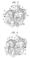
- Figures 5 and 6 are perspective views showing the details of the suction recovery device
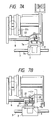
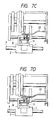
- Figures 7A - 7D are plan views showing the capping and the operation of an atmosphere release valve 23
- Figure 8 is a timing chart illustrating the operation of an embodiment of the present invention
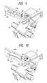
- Figures 9 - 11 are schematic perspective views showing second to fourth embodiments of the present invention.
- the reference numeral 1 designates a recording head provided with a plurality of discharge ports for discharging ink droplets therethrough in conformity with recording information by energy generating means (such as a piezo-electric element, a resistance heat generating member or the like) contained in the recording head
- the reference numeral 2 denotes a carriage carrying the recording head 1 thereon and movable in the main scanning direction
- the reference numeral 3 designates a carriage shaft slidably supporting the carriage 2
- the reference numeral 4 denotes a recording medium.
- the reference numeral 5 designates a feed roller for conveying the recording medium in conformity with the recording situation.
- the reference numeral 6 denotes a pulse motor which is a drive source for the feed roller 5 and for effecting automatic paper supply
- the reference numeral 7 designates a pump carriage capable of recovering a cap unit and movable in parallelism to the carriage shaft 3
- the reference numeral 8 denotes a guide shaft for guiding the parallel movement of the pump carriage 7
- the reference numeral 9 designates a return spring for biasing the pump carriage 7 rightwardly as viewed in Figure 1.
- the pump carriage 7 is provided with an arm 7a, in the fore end portion of which there is formed an aperture 7b into which a projection 2a provided on the right side of the carriage can fit.
- the projection 2a fits into the aperture 7b when the carriage 2 is moved to the left, thereby preventing the carriage 2 from vertically pivoting when a cap 17 is capped on the discharge port surface of the recording head 1.
- one end of a leaf spring 10 having resiliency in the direction of movement of the carriage is fixed to the rear of the pump carriage 7. Further, the other end of the leaf spring 10 is held so as to be nipped by a slide gear supporting bed 12 which supports a slide gear 11.
- the slide gear supporting bed 12 is provided for movement along a slide shaft 13 in the direction of movement of the carriage. Accordingly, the slide gear 11 is stopped in a position in which it is pressed by the resilient force of the leaf spring 10. Therefore, the carriage 2 is moved and the projection 2a of the carriage 2 bears against the arm 7a of the pump carriage 7 and is moved with the latter, whereby the slide gear 11 is moved in the direction of movement of the carriage.
- the slide gear 11, as shown in Figure 3, is in meshing engagement with a gear independently rotated in parallelism to the direction of movement of the carriage.
- the reference numeral 14 designates a feed gear for transmitting a drive force to a sheet feed gear
- the reference numeral 15 denotes an ASF (automatic sheet feeder) gear for transmitting the drive force of an ASF
- the reference numeral 16 designates a pump gear for transmitting the drive force to the suction recovery device.
- the pump gear 16 comprises two gears made integral with each other, and the left gear 16b is in meshing engagement with the pump cam 28 of the suction recovery device. Accordingly, depending on the stopped position of the carriage 2, the slide gear 11 meshes with one of the gears 14, 15 and 16 through the pump carriage 7 and the leaf spring 10 so that the drive force of the pulse motor 6 can be selectively transmitted.
- Figure 4 is a cross-sectional view showing the details of the capping unit.
- the cap 17 is formed by the use of an elastic member of rubber or the like urged against the outer edge portion of the discharge port surface of the head with elasticity, and has a vent hole 17a and a driving space 17b. Also, the cap 17 is supported by a cap holder 18, which is held by a holder 19. A projection 18a which is like a rod having its top end portion extending through the rear wall of the holder 19 is formed on the back of the cap holder 18, and a coil spring 20 is fitted on this projection 18a. An E-ring 21 for regulating the movement of the cap holder 18 toward the head is mounted on the tip end portion of the projection 18a.
- the cap holder 18 is movable to the left and right as viewed in Figure 4 relative to the holder 19 by a guide, not shown, which is provided on the holder 19, and the holder 19 is movable in the direction indicated in Figure 4 relative to the pump carriage 7 by a guide, not shown, which is provided on the pump carriage 7.
- a groove 19a is formed in the rear of the holder 19, and a rail 22 is inserted in the groove 19a.
- the rail 22 is divided into two upper and lower rails (in this case, the rails 22a and 22b should only move independently of each other, and a single rail may be divided into two intermediately thereof even if the two are independent of each other), and the lower rail 22b is used to move the holder 19 forwardly and backwardly relative to the recording head 1, and the upper rail 22a is used to open and close an atmosphere release valve 23.
- a rail arm portion 22c is provided on the back of the rail 22, and a rail dowel 22d is provided on the fore end of the rail arm portion 22c.
- the rail 22 is stopped by a pump base 25, as shown in Figure 5.
- the atmosphere release valve 23 is provided on the back of the holder 19 and is biased leftwardly by a spring 24. Accordingly, the atmosphere release valve 23 is movable to the left and right along the rail 22a as viewed in Figure 4.
- the mounting of the atmosphere release valve 23 is accomplished by inserting it from above the holder 19 and fixing it.
- the atmosphere release valve 23 lies in front of the vent hole 17a provided in the cap 17, and by this vent hole 17a being closed by the atmosphere release valve 23, the space 17b can be hermetically sealed.
- An ink absorbing member 69 is disposed on the bottom of the cap 17, and absorbs and retains ink during the suction of the ink to thereby prevent the desiccation of the nozzle during capping.
- the rail 22 is formed of a resilient material, and when viewed from the upper portion of the printer, it is of a shape which protrudes toward the recording head 1 as shown in Figures 7A - 7D. Accordingly, the projection 2a of the carriage 2 bears against the arm 7a of the pump carriage 7, the pump carriage 7 and the carriage 2 are moved together, the holder 19 and the atmosphere release valve 23 are moved along the shape of the rail 22, and at the stage of Figure 7B, the cap 17 is urged against the discharge port surface of the head.
- the rail 22 deviates by a distance l in the lengthwise direction and therefore, the atmosphere release valve 23 has not climbed up the rising positions of the rails 22a and 22b and has not closed the vent hole 17a of the cap 17 even if the rising angle and the amount of displacement of the rail 22 remain unchanged, and therefore the space 17b between the cap 17 and the recording head 1 is in communication with the atmosphere and the recording head 1 is not pressed by capping and thus, the non-discharge by the recession of meniscus in the discharge port portion does not occur.
- the atmosphere release valve 23 closes the vent hole 17a of the cap 17 and the space 17b becomes hermetically sealed.
- the carriage 2 is further moved to the left and comes to the position of Figure 7C, the slide gear 11 comes into meshing engagement with the pump gear 16 and the suction recovery device operates.
- a suction tube 26 is connected to the cap 17 as shown in Figures 4-6 and the other end thereof is connected to a cylinder 27 as shown in Figure 5 and therefore, negative pressure produced in this cylinder 27 is directed to the space 17b through the suction tube 26.
- the rotational force of the pulse motor 6 is transmitted to the pump gear 16 ⁇ the gear 16b ⁇ the gear portion of the pump cam 28 in the named order.
- the pump cams 28 and 29 are made integral with a positioning dowel, not shown, and are rotatable relative to the pump cam shaft 30.
- Elliptical groove portions are provided in the opposed surfaces of the pump cams 28 and 29 as shown in Figure 6 so that the opposite ends of a parallel pin 32 integrally coupled to a piston 31 may be slidable, and the parallel pin 32 moves up and down in response to the rotation of the cams to thereby move the piston 31 up and down.
- the pump cam 29 is provided with a projection 34 for depressing one end of a pump flag 33, which is rotatable about the guide shaft 8.
- a transmission type sensor 35 is provided at a location opposed to the other end portion 33a of the pump flag 33 (the lower portion of the carriage 2 shown in Figure 1). While the projection 34 is rotated and bears against one end of the pump flag 33, the other end portion 33a of the pump flag 33 intercepts light rays sent from the light emitting portion of the transmission type sensor 35 to the light receiving portion thereof, whereby from this point of time at which the light rays are intercepted, the pulse number of the pulse motor 6 is controlled and thus, the position control of the suction recovery device becomes possible.
- the pump flag 33 When from this state, the projection 34 is further rotated and comes out of engagement with one end of the pump flag 33, the pump flag 33 is reversely rotated about the guide shaft 8 by the gravity thereof or the resilient force of a spring. Thus, the light rays emitted from the transmission type sensor 35 become able to be transmitted through the other end 33a of the pump flag 33.
- the pump flag 33 is stopped from rotating by a stopper, not shown, which is provided on the pump base 25.
- a stopper not shown
- On the right side of the pump cam 28 there are provided a cam 28b for guiding the dowel portion 22d of the arm 22c provided on the rail 22a and a cam (not shown) for guiding a rubbing lever 36.
- the rubbing lever 36 is supported by the pump base 25 and is rotatable relative to the recording head 1.
- the rear of the rubbing lever 36 is guided by a cam, not shown, which is provided on the right side of the pump cam 28, and is subjected to rotation when it rides onto this cam so that a rubbing member 37 (which is provided at the right of the rubbing lever 36 and is formed, for example, of an ether polyurethane continuous porous material) can be advanced to a position in which it overlaps with the recording head 1.
- a rubbing member 37 which is provided at the right of the rubbing lever 36 and is formed, for example, of an ether polyurethane continuous porous material
- the carriage 2 is moved from left to right until it comes to the front face of the rubbing member 37, whereby ink, impurities, etc. on the discharge port surface of the recording head 1 are removed and the discharge stability of the recording head 1 is secured.
- the pressure contact force of the rubbing member 37 against the recording head 1 can be provided by the use of the resilient force of the rubbing member 37 itself or by a resilient member being discretely provided rearwardly of the rubbing member 37 (the pressure contact force is e.g. of the order of 100 g).
- a projection 28c is provided on the upper portion of the pump cam 28, and this projection 28c presses the rear of the holder 19, whereby the rail 22b and the cap 17 are elastically deformed to thereby introduce air into the discharge ports and remove a minute bubble which is a cause of unsatisfactory printing.
- This minute bubble is discharged out of the head with a large bubble which is formed by the introduction of air.
- the cam 28b is liberated from the dowel portion 22d of the arm 22c
- the rail 22a releases the pressure to the atmosphere release valve 23, which is thus pushed back by the resilient force of the spring 24, and atmosphere is introduced into the cap 17 which has so far been hermetically sealed.
- a wiper 38 is provided on the right side plate of the pump base 25.
- This wiper 38 is, for example, a silicone rubber plate having a thickness of 0.3 mm, and is fixed so as to normally overlap with the recording head 1 (the amount of overlap thereof is e.g. 1.0 mm).
- the discharge port surface is wiped by the wiper, whereby paper powder, dust, ink dregs, etc. adhering to the discharge port surface are removed.
- the carriage 2 When from this state, the carriage 2 is further moved to the left, it comes to a position in which the suction recovery device is driven. In this state, the atmosphere release valve 23 has already closed the vent hole 17a of the cap 17 and the space 17b between the recording head 1 and the cap 17 is hermetically sealed.
- the pump cams 28 and 29 begin to rotate and at first, the projection 34 on the surface of the pump cam 29 pushes up one end of the pump flag 33 and the other end portion 33a of the pump flag 33 intercepts the light rays of the transmission type sensor 35 disposed in the lower portion of the carriage 2.
- This position is defined as the initial position of the suction recovery device and the pulse number of the pulse motor 6 is controlled.
- the pump cams 28 and 29 further rotate and the projection 34 passes the pump flag 33, the pump flag 33 returns to its original position and the light rays of the transmission type sensor 35 become non-intercepted.
- the carriage 2 is then moved leftwardly again and is set to a position in which the driving of the suction recovery device becomes possible.
- the pump cam 28 is rotated to press the rear of the holder 19 and the cap 17 is brought into pressure contact with the discharge port surface of the recording head 1 and further, air is introduced into the discharge ports, whereafter the piston 31 is depressed by the rotation of the pump cams 28 and 29.
- Negative pressure produced in the cylinder 27 at this time acts on the space formed in the cap 17, through the suction tube 26, and sucks the ink in the discharge ports. Thereby, minute bubbles in the discharge ports which are the cause of unsatisfactory discharge and dust, impurities, etc. adhering to the discharge port surface are removed.
- design is made such that the dowel 22d provided at the fore end of the rail 22 is pulled rearwardly by the cam 28b and the rail 22a is elastically deformed and pulled rearwardly and the atmosphere release valve 23 is retracted.
- the vent hole of the cap 17 is opened, the space 17b in the cap 17 is communicated with the atmosphere, the ink suction from the discharge ports is stopped, air flows into the cap through the vent hole 17a due to the negative pressure in the cylinder 27 and is sucked into the cylinder 27 with the ink in the space 17b. Accordingly, ink overflow does not occur in the cap 17 and the ink adhering to the discharge port surface is removed.
- the pump cam 28 further rotating, the rearward pull of the rail 22a is released and the rail 22a restores its original shape by its resiliency, and the vent hole 17a is again closed by the atmosphere release valve 23.
- one sequence of recovery operation is terminated.
- the cylinder 27 is pressurized when the piston 31 is moved upwardly, and the sucked ink is discharged as waste ink from a waste ink intake port 91 through a waste ink tube 90 into a waste ink reservoir (not shown) in an ink cartridge 92.
- Figure 9 is a schematic perspective view showing the essential portions of a second embodiment of the present invention.
- an atmosphere release valve 39 (having the same function as that of the atmosphere release valve 23) and a holder 40 (having the same function as that of the holder 19) are constructed so as not to deviate in the direction of movement along the rail.
- the two are horizontally spaced apart from each other by l , whereas in the present embodiment, the two are disposed so as to overlap with each other in the vertical direction, and are arranged so as not to have any deviation in the horizontal direction (the direction of movement along the rail).
- Design is also made such that the rising position of a rail 41a along which the atmosphere release valve 39 moves is delayed with respect to the rising position of a rail 41b, and at the moment of capping, the atmosphere release valve 39 has not yet climbed up the rail 41a and the atmosphere is in communication with the interior of the cap 17. Thereby, the pressing agains the discharge ports during capping can be eliminated.
- Figure 10 is a schematic perspective view showing the essential portions of a third embodiment of the present invention.
- the rising positions are made to differ from each other, whereas in this embodiment, the rising angles of the rails 44a and 44b of a rail 44 are made to differ from each other so that the timing at which the atmosphere release valve 39 closes the vent hole 17a may be delayed in time with respect to capping.
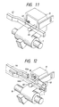
- Figure 11 is a schematic perspective view showing the essential portions of a fourth embodiment of the present invention.
- the end portion of the rail is not divided so that with the rail kept single, an atmosphere release valve 45 and a holder 46 may be driven, and the atmosphere release valve 45 and the holder 46 are installed with a sufficient spacing kept therebetween.
- the plan view movement of the atmosphere release valve 45 can be delayed in time with respect to capping.
- the present embodiment enables the shape of the rail to be simplified, and becomes easy to manufacture.
- the suction recovery device in the liquid jet recording apparatus is a suction recovery device in a liquid jet recording apparatus in which the discharge port surface of a recording head is capped by a cap in response to the movement of a carriage carrying said recording head thereon and which is provided with an atmosphere release valve for introducing the atmosphere into said cap after the suction of ink from the discharge ports and wherein provision is made of one or more rails disposed on the back of said cap in parallelism to the direction of movement of said cap, and driving means for providing a time difference between the capping drive timing of said cap and the valve closing timing of said atmosphere release valve in response to the movement of said carriage to the suction recovery position and therefore, the capping drive of the cap and the valve closing drive of the atmosphere release valve can be effected without the provision of an exclusive actuating member of complicated construction.
- the atmosphere release valve and the cap driving mechanism can be driven in response to the movement of the carriage to the suction recovery area.
- said rail is plural, if the level difference portion of the rail for the capping drive of said cap is provided more toward the printing area relative to the level difference portion of the rail for the valve closing of said atmosphere release valve or the level difference portion of the rail for the valve closing of said atmosphere release valve is provided at the same location as the level difference portion of the rail for the capping drive of said cap and design is made such that the angle of inclination thereof is gentle, a series of operations for suction recovery can be automatically performed in conformity with the movement of the carriage and the state of contact of each member with the rails.
- FIG. 12 to 16 Reference is now had to Figures 12 to 16 to describe embodiments of a suction recovery device in a liquid jet recording apparatus in which the discharge port surface of a recording head is capped by a cap in response to the movement of a carriage carrying said recording head thereon and which is provided with an atmosphere release valve for introducing the atmosphere into said cap after the suction of ink from the discharge ports and wherein provision is made of one or more rails disposed on the back of said cap in parallelism to the direction of movement of said carriage and having resiliency, and driving means for effecting the back and forth driving of said cap and the opening-closing drive of said atmosphere release valve by the use of the pressure force of said rail or rails deformable in conformity with the contact movement of an actuating member movable in response to the movement of said carriage.
- At least the movable end side of said rail or rails be formed of an elastically deformable material.
- a portion of said rail or rails may use a material differing from the material of the essential portion.
- said rail or rails may be provided with at least one hinge.
- design may be made such that said rail or rails are moved as means for effecting the back and forth driving of the atmosphere release valve and the cap.
- a cap holder moves in response to the movement of the carriage to the suction recovery area, and an arm as an actuating member provided on this cap holder and the atmosphere release valve are operated under the pressure of the rail or rails. Accordingly, it becomes possible to effect the capping drive of the cap and the valve closing drive of the atmosphere release valve without an exclusive actuating member of complicated construction which is operable in response to the movement of the carriage being provided on each of the cap and the atmosphere release valve.
- At least a portion of the rail or rails is endowed with a resilient force or a hinge and the actuating member bears against that portion or the vicinity thereof, whereby the rail or rails are deformed, and a capping drive member for the cap and a drive member for the atmosphere release valve are pressed. Accordingly, a driving moment can be provided by only the rail or rails and thus, the simplification of the construction becomes possible.
- the rail or rails can be moved in the vertical direction to thereby effect the opening-closing drive of the atmosphere release valve and therefore, likewise a driving moment can be provided by only the rail or rails and thus, the simplification of the construction becomes possible.
- Figure 12 is a schematic perspective view showing the essential portions of a fifth embodiment of the present invention.
- This embodiment as compared with the construction of Figure 9 in which the fore end portion 42 is made thin, is characterized in that a resilient plate 43 of a material differing from the material of a rail 44 (which is formed of a plastic material) is provided in this portion.
- the material of this resilient plate 43 may be, for example, stainless steel for spring.
- the rising angles are made to differ from each other, whereas in the present embodiment, the rising positions of the rails 44a and 44b are made to differ from each other so that the timing at which the atmosphere release valve 39 is closed may be delayed in time with respect to capping and the interior of the space 17b may not be pressurized during the capping by the cap.
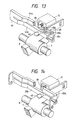
- Figure 13 is a schematic perspective view showing the essential portions of a sixth embodiment of the present invention.
- the atmosphere release valve 39 is driven by the use of the resilient plate 43, whereas in the present embodiment, a movable portion 45 is provided on the back of a rail in the mounting portion for the atmosphere release valve. Therefore, the fore end portion of the upper rail 44a is separated, a leaf spring 45a is fixed to the body side and the fore end thereof presses the rail 44c on the separated side.
- the rail 44c is pivotally coupled to the end portion of the rail 44a by a hinge 45b. In this construction, the rail 44a is not resiliently deformed, but the rail 44c pivots about the hinge 45b. In this case, the resilient deformation of the rail 44a is not utilized and therefore, fatigue destruction or crack attributable to the repetition of resilient deformation does not occur to the rail 44a.
- hinges may also be provided at a plurality of locations. By providing a plurality of hinges, the freedom of movement of the rail is increased and a varying movement can be obtained. Also, the hinge has been shown as being provided on the upper rail, but alternatively, it may be provided on the lower rail.
- Figure 14 is a schematic perspective view showing the essential portions of a seventh embodiment of the present invention.
- the opening and closing of the atmosphere release valve 39 is effected by the use of the resilient deformation of the rail, whereas in the present embodiment, the opening and closing of the atmosphere release valve is effected by moving the entire rail 22 (in the present embodiment, moving it in the vertical direction).
- a drive source for the movement of the rail 22 can be achieved by parallel-moving the rail perpendicularly to the plane of movement thereof by an unshown pump cam (or other means). Accordingly, in this construction, the rails 22a and 22b are not integral with each other, but are independent of each other. Although only the upper rail 22a is shown, it is also possible to move the lower rail 22b in a similar manner to thereby effect the opening and closing of the cap 17.
- Figure 15 is a schematic perspective view showing the essential portions of an eighth embodiment of the present invention.
- the upper rail 44a and lower rail 44b of the rail 44 of Figure 13 are separated from each other and the opposite sides of the upper rail 44a are supported by a pair of arms 46a, 46b and a pair of hinges 46c, 46d so that the entire upper rail 44a can move in the direction of movement of the carriage (the horizontal direction).
- the upper rail 44a has an inclined portion in the direction of thickness thereof, and the atmosphere release valve 39 moves up and down along the inclined portion in conformity with the movement of the upper rail 44a, whereby the opening and closing of the valve is effected.
- the upper rail 44a but also the lower rail 44b can be designed to be moved.
- the opening-closing drive of the atmosphere release valve 39 and cap 17 can be accomplished.
- Figure 16 is a schematic perspective view showing the essential portions of a ninth embodiment of the present invention.
- the rails are of rectangular cross-sectional shape, whereas this embodiment is characterized in that use is made of an upper rail 47a having in the lower portion thereof a protrusion 47c protruding in the direction opposite to the cap 17 and this upper rail 47a is made vertically movable.
- the atmosphere release valve 39 is closed when the upper rail 47a is moving so that the flat surface thereof may bear against the atmosphere release valve 39.
- the protrusion 47c is opposed to the atmosphere release valve 39 and the latter is opened.
- centers of rotation 47f and 47g can be provided in the end portions of arms 47d and 47e formed at the opposite ends of the rail and design can be made such that the upper rail 47a is pivoted with those centers of rotation as a fulcrum.
- a suction recovery device in a liquid jet recording apparatus in which the discharge port surface of a recording head is capped by a cap in response to the movement of a carriage carrying said recording head thereon and which is provided with an atmosphere release valve for introducing the atmosphere into said cap after the suction of ink from the discharge ports, provision is made of one or more rails disposed on the back of said cap in parallelism to the direction of movement of said carriage and having resiliency, and driving means for effecting the back and forth drive of said cap and the opening-closing drive of said atmosphere release valve by the use of the pressure force of said rail deformed in conformity with the contact movement of an actuating member moving in response to the movement of said carriage and therefore, it becomes possible to effect the capping drive of the cap and the opening-closing drive of the atmosphere release valve without providing an exclusive actuating member of complicated construction.
- At least the movable end side of said rail or rails is formed of a resiliently deformable material or a portion of said rail or rails uses a material differing from the material of the essential portion thereof or a hinge is provided, whereby said pressure force can be provided simply.
- said rail or rails are moved and therefore, the driving for the back and forth movement of the atmosphere release valve and the carriage can be accomplished by a simple construction like that which endows the rail or rails with a resilient force.
- FIG. 17 to 21 an ink jet recording apparatus provided with a recovery device in which a cap of elastic material is urged against the discharge port surface of a recording head to produce negative pressure in said cap and suck ink in the discharge ports and a flow path for communicating the interior of said cap with the atmosphere and a pressure contact portion for an opening-closing valve member are provided in said cap or a portion integral therewith, whereby the joint portion of a tube can be eliminated to thereby eliminate a problem of disconnection or the like and the assembling work can be improved and moreover, even if the cap moves, the position thereof relative to the opening-closing valve can be maintained as it is and the hermetically sealing function of said opening-closing valve can be improved.
- a negative pressure introduction hole 66 to which is connected a tube 65 leading to the suction pump 22, and a flow path 67 for communication with the atmosphere.
- the cap 17 is integrally held by a cap holder 63.
- the cap holder 63 is supported on a cap carriage 62 for movement in the longitudinal direction thereof through a support rod 68, a support pin 69 and a return spring 70 and is also supported for pivotal movement within a predetermined range about the support pin 69.
- a valve member 72 biased in a direction to open by a valve spring 71 is mounted at a location on the cap holder 63 which is opposed to the flow path 67.
- This valve member 72 is for opening and closing the flow path 67 to thereby communicate the interior of the cap 17 with the atmosphere and cut off the communication.
- a push pin 73 for operating the valve member 72 is slidably mounted on the cap carriage 62.
- Figure 20 is a time chart showing the operations of the cap 17, the atmosphere release valve (valve member 72) and the suction pump 22 of the recovery device of Figure 17 and a variation in the pressure in the cap 17.
- the pump 22 is not yet in operation.
- the interior of the cap 17 is in the atmospheric pressure state and the pressurization in the discharge ports of the recording head by the cap 17 being elastically deformed during capping to thereby decrease the volume in the cap 17 is prevented.
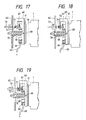
- Figure 19 shows the state at a point of time B which is T1+T2 after the start of the operation.
- the push pin 73 is pushed in the direction of arrow by a drive source, not shown, to push the atmosphere release valve 72 into pressure contact with the end surface of the flow path 67 (the portion pressure-contacted by the opening-closing valve member 72), whereby the flow path 67 for communication with the atmosphere is shut off.
- the suction pump 22 is driven to suck the air in the cap 17 and bring the interior of the cap 17 into a negative pressure state.
- the ink in the discharge ports of the recording head 1 is sucked out by this negative pressure.
- the push pin 73 is retracted to open the valve member (atmosphere release valve) 72 and thereby communicate the interior of the cap 17 with the atmosphere.
- a point of time C after the lapse of time T3 from the point of time B corresponds to the time when this communication with the atmosphere is being effected.
- the air stream created by the communication with the atmosphere being thus effected while there is the suction force of the pump is utilized to blow off ink droplets adhering to the discharge port surface 1A of the recording head 1 and also suck out the ink collected in the cap 17.
- Figure 19 shows a state in which the cap 17 is in its enveloping position and the atmosphere release valve 72 also is in its enveloping position, that is, a state when the ink is sucked.
- the opening-closing valve member (atmosphere release valve) 72 is mounted on the cap holder 63 integrally coupled to the cap 17 and therefore, the valve member 72 does not positionally deviate relative to the flow path 67 for communication with the atmosphere and the flow path 67 is reliably enveloped.
- the flow path 67 for communication with the atmosphere is formed in the cap 17 itself and the valve member 72 for opening and closing the flow path 67 is mounted on the cap holder 63 (the portion which is substantially integral with the cap 17) integrally assembled to the cap 17 and therefore, there is provided an ink jet recording apparatus provided with a recovery device in which, as compared with the prior-art structure, the joint portion of the tube can be eliminated to eliminate a problem of disconnection or the like and the assembly work can be improved and moreover, even if the cap 17 moves, the position thereof relative to the opening-closing valve 72 can be maintained as it is and the hermetically sealing function of the opening-closing valve 72 can be improved.
- Figure 21 is a side view showing another embodiment of the atmosphere release valve of the recovery device in the ink jet recording apparatus according to the present invention.
- an atmosphere release valve (valve member) 72 is formed integrally with the cap holder 63, and this valve member 72 is supported on the body portion of the cap holder 63 by a spring portion 75 of small cross-sectional area having a spring property.
- the atmosphere release valve 72 may also be of the type which opens and closes the flow path 67 by a rotating movement using a link, instead of a straight movement.
- an ink jet recording apparatus provided with a recovery device in which a cap of elastic material is urged against the discharge port surface of a recording head and negative pressure is produced in said cap to suck the ink in the discharge ports and in which a flow path for communicating the interior of said cap with the atmosphere and a portion pressure-contacted by an opening-closing valve member are provided in said cap or a portion integral therewith and therefore the joint portion of a tube can be eliminated to eliminate a problem of disconnection and the assembling work can be improved and moreover, even if the cap moves, the position thereof relative to the opening-closing valve can be maintained as it is and the hermetically sealing function of the opening-closing valve can be improved.
- an ink jet recording apparatus in which, in addition to the above-described construction, positioning means for fitting to a carriage carrying a recording head thereon is provided on a cap supporting member for supporting said cap and therefore the positional deviation between the cap and the discharge port surface of the recording head is eliminated to thereby enable the recovery operation to be performed more reliably.
- a suction recovery device in a liquid jet recording apparatus in which the discharge port surface of a recording head is capped by a cap in response to the movement of a carriage carrying the recording head thereon and which is provided with an atmosphere release valve for introducing the atmosphere into the cap after or during the suction of ink from the discharge ports, provision is made of one or more rails disposed on the back of the cap in parallelism to the direction of movement of the carriage, and driving means for providing a time difference between the timing of the capping drive of the cap and the valve closing timing of the atmosphere release valve in response to the movement of the carriage to the suction recovery position.
Landscapes
- Engineering & Computer Science (AREA)
- Environmental & Geological Engineering (AREA)
- Ink Jet (AREA)
Applications Claiming Priority (6)
| Application Number | Priority Date | Filing Date | Title |
|---|---|---|---|
| JP22632289A JP2704297B2 (ja) | 1989-08-31 | 1989-08-31 | 液体噴射記録装置 |
| JP226322/89 | 1989-08-31 | ||
| JP226323/89 | 1989-08-31 | ||
| JP22632389A JP2704298B2 (ja) | 1989-08-31 | 1989-08-31 | 液体噴射記録装置 |
| JP319717/89 | 1989-12-08 | ||
| JP31971789A JP2687026B2 (ja) | 1989-12-08 | 1989-12-08 | インクジェット記録装置 |
Publications (2)
| Publication Number | Publication Date |
|---|---|
| EP0423475A1 true EP0423475A1 (de) | 1991-04-24 |
| EP0423475B1 EP0423475B1 (de) | 1997-01-22 |
Family
ID=27331153
Family Applications (1)
| Application Number | Title | Priority Date | Filing Date |
|---|---|---|---|
| EP90116655A Expired - Lifetime EP0423475B1 (de) | 1989-08-31 | 1990-08-30 | Absaug-Regeneriervorrichtung für ein Tintenstrahlaufzeichnungsgerät |
Country Status (5)
| Country | Link |
|---|---|
| US (2) | US5153613A (de) |
| EP (1) | EP0423475B1 (de) |
| KR (1) | KR950004571B1 (de) |
| CN (1) | CN1034643C (de) |
| DE (1) | DE69029780T2 (de) |
Cited By (21)
| Publication number | Priority date | Publication date | Assignee | Title |
|---|---|---|---|---|
| EP0452585A2 (de) * | 1990-04-19 | 1991-10-23 | Canon Kabushiki Kaisha | Aufzeichnungsgerät |
| US5168291A (en) * | 1989-04-24 | 1992-12-01 | Canon Kabushiki Kaisha | Recording apparatus and ink cassette therefor |
| EP0526209A2 (de) * | 1991-07-31 | 1993-02-03 | Canon Kabushiki Kaisha | Getriebe für Aufzeichnungsgeräte |
| EP0540344A2 (de) * | 1991-10-31 | 1993-05-05 | Canon Kabushiki Kaisha | Rückgewinnungsvorrichtung und Tintenstrahlaufzeichnungsgerät mit einer solchen Rückgewinnungsvorrichtung |
| EP0591844A1 (de) * | 1992-10-02 | 1994-04-13 | Canon Kabushiki Kaisha | Regeneriermechanismus und ein Tintenstrahlgerät mit diesem Mechanismus |
| EP0597675A2 (de) * | 1992-11-12 | 1994-05-18 | Xerox Corporation | Ventil für Tintenstrahldruckerwartungssystem |
| DE4309593A1 (de) * | 1993-03-22 | 1994-09-29 | Inkjet Systems Gmbh Co Kg | Anordnung zur Führung eines Aufzeichnungsträgers |
| EP0635371A2 (de) * | 1993-07-19 | 1995-01-25 | Hewlett-Packard Company | Auslösekappe für einen röhrenlosen Tintenstrahldrucker und damit arbeitendes System |
| US5404158A (en) * | 1992-11-12 | 1995-04-04 | Xerox Corporation | Ink jet printer maintenance system |
| FR2713988A1 (fr) * | 1992-09-10 | 1995-06-23 | Seiko Epson Corp | Imprimante à jet d'encre. |
| EP0676291A1 (de) * | 1994-04-08 | 1995-10-11 | Canon Kabushiki Kaisha | Verbesserte Reinigungsvorrichtung und ein damit versehenes Tintenstrahlaufzeichnungsgerät |
| EP0678389A1 (de) * | 1994-04-21 | 1995-10-25 | Fujitsu Limited | Verfahren und Gerät zur Reinigung eines Tintenstrahlkopfes |
| EP0678388A1 (de) * | 1994-04-20 | 1995-10-25 | Canon Kabushiki Kaisha | Reinigungssystem für einen Tintenstrahldruckkopf |
| WO1996004141A1 (en) * | 1994-07-29 | 1996-02-15 | Mit Modular Ink Technology I Stockholm Ab | Printing arrangement |
| FR2735421A1 (fr) * | 1995-06-13 | 1996-12-20 | Seiko Epson Corp | Appareil d'enregistrement du type a jet d'encre |
| EP0788884A2 (de) * | 1992-06-26 | 1997-08-13 | Seiko Epson Corporation | Tintenstrahlaufzeichnungsvorrichtung |
| DE4345338C2 (de) * | 1992-09-10 | 1998-09-10 | Seiko Epson Corp | Tintenstrahldrucker |
| EP0867295A2 (de) * | 1997-03-25 | 1998-09-30 | Seiko Epson Corporation | Tintenstrahlaufzeichnungsgerät und Tintenabsaugungsverfahren für den Aufzeichnungskopf |
| US5917517A (en) * | 1995-02-21 | 1999-06-29 | Canon Kabushiki Kaisha | Ink jet recording apparatus and wiping method used for such apparatus |
| EP1024961A1 (de) * | 1997-11-01 | 2000-08-09 | Graphic Utilities, Inc. | Tintenstrahlkasettennachfüllvorrichtung, bausatz, station und verfahren |
| EP1090765A1 (de) * | 1998-07-03 | 2001-04-11 | Nec Corporation | Tintenstrahldrucker |
Families Citing this family (43)
| Publication number | Priority date | Publication date | Assignee | Title |
|---|---|---|---|---|
| DE69029780T2 (de) * | 1989-08-31 | 1997-07-10 | Canon Kk | Absaug-Regeneriervorrichtung für ein Tintenstrahlaufzeichnungsgerät |
| FR2672308B1 (fr) * | 1991-02-01 | 1993-05-07 | Staubli Sa Ets | Mecanique d'armure pour la formation de la foule sur les machines a tisser. |
| DE69321783T2 (de) * | 1992-07-28 | 1999-04-29 | Canon Kk | Wischmechanismus für einen Tintenstrahlaufzeichnungskopf und damit versehener Aufzeichnungskopf |
| US6170945B1 (en) | 1992-08-25 | 2001-01-09 | Canon Kabushiki Kaisha | Ink jet recording apparatus with cartridge storage |
| EP0585923B1 (de) * | 1992-09-03 | 1998-12-09 | Canon Kabushiki Kaisha | Farbstrahlaufzeichnungsgerät |
| US5257044A (en) * | 1992-11-12 | 1993-10-26 | Xerox Corporation | Cap actuation mechanism for capping ink jet printheads |
| ATE152671T1 (de) * | 1992-12-28 | 1997-05-15 | Canon Kk | Tintenstrahlaufzeichnungsgerät und rückgewinnungsverfahren dafür |
| JP3233175B2 (ja) * | 1993-03-11 | 2001-11-26 | セイコーエプソン株式会社 | インクジェット式記録装置 |
| US5608432A (en) * | 1993-06-22 | 1997-03-04 | Canon Kabushiki Kaisha | Ink jet apparatus and recovery mechanism therefor |
| US6447095B1 (en) | 1994-05-19 | 2002-09-10 | Canon Kabushiki Kaisha | Discharge recovery method for ink jet apparatus using waterproof ink and ink jet apparatus employing the method |
| EP0696505B1 (de) * | 1994-08-12 | 2001-12-05 | Hewlett-Packard Company, A Delaware Corporation | Kappenausrichtung und Wischerpositionierung zur Reinigung eines Tintenstrahldruckers |
| US5559538A (en) * | 1994-08-12 | 1996-09-24 | Hewlett-Packard Company | Positioning of service station and paper pick pressure plate using single motor |
| US5912681A (en) * | 1994-10-24 | 1999-06-15 | Canon Kabushiki Kaisha | Capping mechanism for ink jet recorder |
| CH690099A5 (fr) * | 1994-12-30 | 2000-04-28 | Ocd Sa | Imprimante à jet d'encre. |
| US5714991A (en) * | 1995-03-03 | 1998-02-03 | Hewlett-Packard Company | Rotary priming system for inkjet printheads |
| JPH08258286A (ja) * | 1995-03-22 | 1996-10-08 | Brother Ind Ltd | インクジェット装置 |
| KR0146534B1 (ko) * | 1995-10-18 | 1998-08-17 | 김광호 | 잉크젯트 프린터의 프린트헤드를 제어하는 회로 및 방법 |
| US5980034A (en) * | 1996-03-11 | 1999-11-09 | Videojet Systems International, Inc. | Cross flow nozzle system for an ink jet printer |
| JP3352588B2 (ja) * | 1996-03-14 | 2002-12-03 | ブラザー工業株式会社 | インクジェット記録装置 |
| US6137510A (en) * | 1996-11-15 | 2000-10-24 | Canon Kabushiki Kaisha | Ink jet head |
| JP3912568B2 (ja) * | 1997-11-07 | 2007-05-09 | ブラザー工業株式会社 | 印字装置 |
| JPH11263028A (ja) * | 1998-03-17 | 1999-09-28 | Nec Niigata Ltd | インクジェット記録装置およびインクジェット記録方法 |
| JP2001058420A (ja) * | 1999-08-24 | 2001-03-06 | Canon Inc | 圧力発生装置、記録装置、および記録装置の制御方法 |
| US6520620B1 (en) * | 2000-04-25 | 2003-02-18 | Lexmark International, Inc. | Gear train for a maintenance station of an ink-jet printer |
| CN100352653C (zh) * | 2000-05-24 | 2007-12-05 | 西尔弗布鲁克研究有限公司 | 带有空气供应装置的打印头 |
| CN101024337B (zh) * | 2000-08-11 | 2011-06-08 | 佳能精技股份有限公司 | 喷墨打印机以及恢复系统的清洗方法 |
| JP2002337415A (ja) * | 2001-03-15 | 2002-11-27 | Canon Inc | キャリッジを備える装置 |
| US6739696B2 (en) * | 2001-04-20 | 2004-05-25 | Seiko Epson Corporation | Apparatus and method for cleaning ink jet printer |
| JP2003048325A (ja) * | 2001-08-06 | 2003-02-18 | Canon Inc | 記録装置 |
| JP2003237092A (ja) * | 2002-02-15 | 2003-08-26 | Canon Inc | インクジェット記録装置 |
| JP4333226B2 (ja) * | 2003-06-13 | 2009-09-16 | セイコーエプソン株式会社 | キャッピング装置、キャッピング方法、及び液滴吐出装置 |
| US7303014B2 (en) * | 2004-10-26 | 2007-12-04 | Halliburton Energy Services, Inc. | Casing strings and methods of using such strings in subterranean cementing operations |
| US7401887B2 (en) * | 2005-10-11 | 2008-07-22 | Silverbrook Research Pty Ltd | Method of maintaining a printhead using air blast cleaning |
| US7387358B2 (en) * | 2005-10-11 | 2008-06-17 | Silverbrook Research Pty Ltd | Printhead maintenance assembly configured for air blast cleaning |
| KR101267066B1 (ko) * | 2006-03-29 | 2013-05-23 | 엘지디스플레이 주식회사 | 폴리이미드막 도포 장치 및 그 방법 |
| US20080158288A1 (en) * | 2006-12-28 | 2008-07-03 | Canon Kabushiki Kaisha | Recording apparatus |
| US20100253738A1 (en) * | 2009-04-03 | 2010-10-07 | Keith Jariabka | Carriage-actuated vent system for inkjet print heads |
| JP5566067B2 (ja) * | 2009-09-11 | 2014-08-06 | キヤノン株式会社 | 記録装置 |
| EP2566697B1 (de) * | 2010-05-02 | 2020-12-09 | Xjet Ltd. | Drucksystem mit anordnungen für selbstreinigung, ablagerungsverhinderung und rauchentfernung |
| US20110279559A1 (en) * | 2010-05-17 | 2011-11-17 | Silverbrook Research Pty Ltd | Printing system having pressure control at printhead |
| JP5935338B2 (ja) * | 2012-01-16 | 2016-06-15 | 株式会社リコー | 画像形成装置 |
| JP6268846B2 (ja) * | 2013-09-19 | 2018-01-31 | セイコーエプソン株式会社 | ヘッドユニット、画像記録装置 |
| JP6828422B2 (ja) * | 2016-12-22 | 2021-02-10 | セイコーエプソン株式会社 | 液体噴射装置及びクリーニング装置 |
Citations (2)
| Publication number | Priority date | Publication date | Assignee | Title |
|---|---|---|---|---|
| DE3611333A1 (de) * | 1985-04-05 | 1986-10-16 | Canon K.K., Tokio/Tokyo | Fluessigkeitsstrahl-aufzeichnungsgeraet und in dem geraet verwendete saug-regeneriereinrichtung |
| US4745414A (en) * | 1986-04-09 | 1988-05-17 | Canon Kabushiki Kaisha | Recovery device for an ink jet recorder and a recovery method thereof |
Family Cites Families (12)
| Publication number | Priority date | Publication date | Assignee | Title |
|---|---|---|---|---|
| JPH089231B2 (ja) * | 1984-01-31 | 1996-01-31 | キヤノン株式会社 | 吐出回復方法 |
| JPS6171443A (ja) * | 1984-09-14 | 1986-04-12 | Toshiba Corp | テ−プレコ−ダの制御装置 |
| JP2516901B2 (ja) * | 1985-06-04 | 1996-07-24 | キヤノン株式会社 | 液体噴射装置の回復方法 |
| JPS61277456A (ja) * | 1985-06-04 | 1986-12-08 | Canon Inc | 液体噴射記録装置における吸引回復装置 |
| JPH089232B2 (ja) * | 1985-06-04 | 1996-01-31 | キヤノン株式会社 | インクジェット装置の回復方法 |
| US5311214A (en) * | 1985-11-08 | 1994-05-10 | Canon Kabushiki Kaisha | Ink jet recording apparatus having means for removing foreign material from an ink supply path by first introducing an into the ink supply path |
| DE3637991A1 (de) * | 1985-11-08 | 1987-05-14 | Canon Kk | Tintenstrahl-aufzeichnungsvorrichtung und regenerierverfahren hierfuer |
| JP2522770B2 (ja) * | 1986-08-05 | 1996-08-07 | キヤノン株式会社 | インクジェット装置 |
| JP2711846B2 (ja) * | 1987-03-13 | 1998-02-10 | キヤノン株式会社 | インクジェット記録装置の操作方法 |
| JPS63224958A (ja) * | 1987-03-13 | 1988-09-20 | Canon Inc | インクジエツト記録装置の作動方法 |
| JP2626805B2 (ja) * | 1987-10-30 | 1997-07-02 | キヤノン株式会社 | インクジェット記録装置 |
| DE69029780T2 (de) * | 1989-08-31 | 1997-07-10 | Canon Kk | Absaug-Regeneriervorrichtung für ein Tintenstrahlaufzeichnungsgerät |
-
1990
- 1990-08-30 DE DE69029780T patent/DE69029780T2/de not_active Expired - Fee Related
- 1990-08-30 EP EP90116655A patent/EP0423475B1/de not_active Expired - Lifetime
- 1990-08-31 KR KR1019900013636A patent/KR950004571B1/ko not_active IP Right Cessation
- 1990-08-31 CN CN90108234A patent/CN1034643C/zh not_active Expired - Fee Related
-
1992
- 1992-03-09 US US07/845,796 patent/US5153613A/en not_active Expired - Lifetime
-
1993
- 1993-11-03 US US08/145,049 patent/US5448271A/en not_active Expired - Fee Related
Patent Citations (2)
| Publication number | Priority date | Publication date | Assignee | Title |
|---|---|---|---|---|
| DE3611333A1 (de) * | 1985-04-05 | 1986-10-16 | Canon K.K., Tokio/Tokyo | Fluessigkeitsstrahl-aufzeichnungsgeraet und in dem geraet verwendete saug-regeneriereinrichtung |
| US4745414A (en) * | 1986-04-09 | 1988-05-17 | Canon Kabushiki Kaisha | Recovery device for an ink jet recorder and a recovery method thereof |
Cited By (51)
| Publication number | Priority date | Publication date | Assignee | Title |
|---|---|---|---|---|
| US5168291A (en) * | 1989-04-24 | 1992-12-01 | Canon Kabushiki Kaisha | Recording apparatus and ink cassette therefor |
| US5627570A (en) * | 1989-04-24 | 1997-05-06 | Canon Kabushiki Kaisha | Ink jet recording method using movable detection flags |
| EP0452585A2 (de) * | 1990-04-19 | 1991-10-23 | Canon Kabushiki Kaisha | Aufzeichnungsgerät |
| EP0452585A3 (en) * | 1990-04-19 | 1992-04-01 | Canon Kabushiki Kaisha | Recording apparatus |
| EP0526209A3 (en) * | 1991-07-31 | 1993-12-01 | Canon Kk | Drive transmission mechanism for recording apparatus |
| US5733055A (en) * | 1991-07-31 | 1998-03-31 | Canon Kabushiki Kaisha | Recording apparatus |
| EP0526209A2 (de) * | 1991-07-31 | 1993-02-03 | Canon Kabushiki Kaisha | Getriebe für Aufzeichnungsgeräte |
| US5883645A (en) * | 1991-10-31 | 1999-03-16 | Canon Kabushiki Kaisha | Recovery mechanism and an ink jet recording apparatus using the recovery mechanism |
| EP0540344A3 (en) * | 1991-10-31 | 1993-12-01 | Canon Kk | Recovery mechanism and an ink jet recording apparatus using the recovery mechanism |
| EP0540344A2 (de) * | 1991-10-31 | 1993-05-05 | Canon Kabushiki Kaisha | Rückgewinnungsvorrichtung und Tintenstrahlaufzeichnungsgerät mit einer solchen Rückgewinnungsvorrichtung |
| EP0788884A2 (de) * | 1992-06-26 | 1997-08-13 | Seiko Epson Corporation | Tintenstrahlaufzeichnungsvorrichtung |
| SG99848A1 (en) * | 1992-06-26 | 2003-11-27 | Seiko Epson Corp | Ink-jet recording device |
| EP0788884A3 (de) * | 1992-06-26 | 1997-11-05 | Seiko Epson Corporation | Tintenstrahlaufzeichnungsvorrichtung |
| US5850235A (en) * | 1992-09-10 | 1998-12-15 | Seiko Epson Corporation | Printer |
| US5946016A (en) * | 1992-09-10 | 1999-08-31 | Seiko Epson Corp. | Printer sheet discharge method |
| FR2713988A1 (fr) * | 1992-09-10 | 1995-06-23 | Seiko Epson Corp | Imprimante à jet d'encre. |
| USRE40581E1 (en) * | 1992-09-10 | 2008-11-25 | Seiko Epson Corporation | Printer including an ink cartridge |
| DE4345338C2 (de) * | 1992-09-10 | 1998-09-10 | Seiko Epson Corp | Tintenstrahldrucker |
| US5742316A (en) * | 1992-09-10 | 1998-04-21 | Seiko Epson Corporation | Actuation mechanism and printer using same |
| US5615873A (en) * | 1992-09-10 | 1997-04-01 | Seiko Epson Corporation | Paper feeder in a printer |
| US6027204A (en) * | 1992-09-10 | 2000-02-22 | Seiko Epson Corporation | Printer including an ink cartridge |
| US5648807A (en) * | 1992-09-10 | 1997-07-15 | Seiko Epson Corporation | Ink jet recording apparatus having an antismear sheet deformation discharge system |
| USRE38926E1 (en) | 1992-09-10 | 2005-12-27 | Seiko Epson Corporation | Printer including an ink cartridge |
| US5751301A (en) * | 1992-10-02 | 1998-05-12 | Canon Kabushiki Kaisha | Ink jet recording apparatus having ink jet head moving structure for gap spacing and recovery |
| EP0591844A1 (de) * | 1992-10-02 | 1994-04-13 | Canon Kabushiki Kaisha | Regeneriermechanismus und ein Tintenstrahlgerät mit diesem Mechanismus |
| US5404158A (en) * | 1992-11-12 | 1995-04-04 | Xerox Corporation | Ink jet printer maintenance system |
| EP0597675A2 (de) * | 1992-11-12 | 1994-05-18 | Xerox Corporation | Ventil für Tintenstrahldruckerwartungssystem |
| EP0597675A3 (de) * | 1992-11-12 | 1994-08-03 | Xerox Corp | |
| DE4309593A1 (de) * | 1993-03-22 | 1994-09-29 | Inkjet Systems Gmbh Co Kg | Anordnung zur Führung eines Aufzeichnungsträgers |
| US5534896A (en) * | 1993-07-19 | 1996-07-09 | Hewlett-Packard Company | Tubeless ink-jet printer priming cap system and method |
| EP0635371A2 (de) * | 1993-07-19 | 1995-01-25 | Hewlett-Packard Company | Auslösekappe für einen röhrenlosen Tintenstrahldrucker und damit arbeitendes System |
| EP0635371A3 (de) * | 1993-07-19 | 1995-08-16 | Hewlett Packard Co | Auslösekappe für einen röhrenlosen Tintenstrahldrucker und damit arbeitendes System. |
| US6189998B1 (en) | 1994-04-08 | 2001-02-20 | Canon Kabushiki Kaisha | Space saving ink jet recovery device and ink jet recording apparatus using the same |
| EP0676291A1 (de) * | 1994-04-08 | 1995-10-11 | Canon Kabushiki Kaisha | Verbesserte Reinigungsvorrichtung und ein damit versehenes Tintenstrahlaufzeichnungsgerät |
| US5917513A (en) * | 1994-04-20 | 1999-06-29 | Canon Kabushiki Kaisha | Ink jet recording apparatus with recovery pump operated by movement of carrier |
| EP0678388A1 (de) * | 1994-04-20 | 1995-10-25 | Canon Kabushiki Kaisha | Reinigungssystem für einen Tintenstrahldruckkopf |
| CN1058226C (zh) * | 1994-04-20 | 2000-11-08 | 佳能株式会社 | 喷墨设备 |
| EP0678389A1 (de) * | 1994-04-21 | 1995-10-25 | Fujitsu Limited | Verfahren und Gerät zur Reinigung eines Tintenstrahlkopfes |
| US5784081A (en) * | 1994-04-21 | 1998-07-21 | Fujitsu Limited | Method of and apparatus for cleaning ink jet head |
| WO1996004141A1 (en) * | 1994-07-29 | 1996-02-15 | Mit Modular Ink Technology I Stockholm Ab | Printing arrangement |
| US5917517A (en) * | 1995-02-21 | 1999-06-29 | Canon Kabushiki Kaisha | Ink jet recording apparatus and wiping method used for such apparatus |
| US5898444A (en) * | 1995-06-13 | 1999-04-27 | Seiko Epson Corporation | Ink jet type recording apparatus having a capping device and a CAM follower |
| DE19623626B4 (de) * | 1995-06-13 | 2005-12-15 | Seiko Epson Corp. | Tintenstrahlaufzeichnungsvorrichtung |
| FR2735421A1 (fr) * | 1995-06-13 | 1996-12-20 | Seiko Epson Corp | Appareil d'enregistrement du type a jet d'encre |
| EP0867295A2 (de) * | 1997-03-25 | 1998-09-30 | Seiko Epson Corporation | Tintenstrahlaufzeichnungsgerät und Tintenabsaugungsverfahren für den Aufzeichnungskopf |
| US6312092B1 (en) | 1997-03-25 | 2001-11-06 | Seiko Epson Corporation | Ink jet recording apparatus and ink suction method of the recording head |
| US6540322B2 (en) | 1997-03-25 | 2003-04-01 | Seiko Epson Corporation | Ink jet recording apparatus and ink suction method of the recording head |
| EP0867295A3 (de) * | 1997-03-25 | 1999-01-27 | Seiko Epson Corporation | Tintenstrahlaufzeichnungsgerät und Tintenabsaugungsverfahren für den Aufzeichnungskopf |
| EP1024961A4 (de) * | 1997-11-01 | 2001-01-31 | Graphic Utilities Inc | Tintenstrahlkasettennachfüllvorrichtung, bausatz, station und verfahren |
| EP1024961A1 (de) * | 1997-11-01 | 2000-08-09 | Graphic Utilities, Inc. | Tintenstrahlkasettennachfüllvorrichtung, bausatz, station und verfahren |
| EP1090765A1 (de) * | 1998-07-03 | 2001-04-11 | Nec Corporation | Tintenstrahldrucker |
Also Published As
| Publication number | Publication date |
|---|---|
| CN1034643C (zh) | 1997-04-23 |
| EP0423475B1 (de) | 1997-01-22 |
| US5448271A (en) | 1995-09-05 |
| KR950004571B1 (ko) | 1995-05-02 |
| US5153613A (en) | 1992-10-06 |
| CN1051698A (zh) | 1991-05-29 |
| DE69029780D1 (de) | 1997-03-06 |
| DE69029780T2 (de) | 1997-07-10 |
| KR910004359A (ko) | 1991-03-28 |
Similar Documents
| Publication | Publication Date | Title |
|---|---|---|
| EP0423475B1 (de) | Absaug-Regeneriervorrichtung für ein Tintenstrahlaufzeichnungsgerät | |
| US6106098A (en) | Ink jet recording apparatus having respective capping members for plural recording heads | |
| US4970534A (en) | Ink jet recovery device having a spring-loaded cap and a mechanism for pressing the cap against a recording head and apparatus incorporating the device | |
| JP3576649B2 (ja) | インクジェット印刷装置のサービスステーション | |
| EP0788884B1 (de) | Tintenstrahlaufzeichnungsvorrichtung | |
| EP1354708A1 (de) | Vorrichtung zur Reinigung eines Tintenstrahldruckkopfes | |
| US6511153B1 (en) | Preliminary discharge acceptor mechanism and printing apparatus provided with the preliminary discharge acceptor mechanism | |
| JPH04211964A (ja) | 吸引回復装置および該装置を具えたインクジェット記録装置 | |
| US6886907B1 (en) | Cleaning device for cleaning printhead of ink-jet printer | |
| US6648456B1 (en) | Printing apparatus | |
| EP1040924B1 (de) | Tintenstrahlaufzeichnungsgerät | |
| US4682184A (en) | Suction recovering device for an ink jet printer and ink jet printer having the same device | |
| EP0720913A2 (de) | Pflegevorrichtung in einem Tintenstrahldrucker | |
| US6039432A (en) | Ink jet recording apparatus with recovering device of ink jet head | |
| US5917515A (en) | Ink jet printer having backup unit with any one or both of a pump mechanism and a nozzle cap mechanism | |
| JP2003191481A (ja) | インクジェット式記録装置 | |
| JP3536958B2 (ja) | インクジェット記録装置 | |
| GB2315710A (en) | Controlled suction of ink jet recording head | |
| JPH1067116A (ja) | インクジェット方式の画像形成装置 | |
| JPH03180354A (ja) | インクジェット記録装置 | |
| JPH0829592B2 (ja) | インクジェット記録ヘッドのキャッピング方法 | |
| JP2704298B2 (ja) | 液体噴射記録装置 | |
| JPH07323571A (ja) | インクジェット記録装置および情報処理システム | |
| JPH10109432A (ja) | インク吸引手段 | |
| JPH05229131A (ja) | 吸引回復装置とこの装置を備えたインクジェット記録装置 |
Legal Events
| Date | Code | Title | Description |
|---|---|---|---|
| PUAI | Public reference made under article 153(3) epc to a published international application that has entered the european phase |
Free format text: ORIGINAL CODE: 0009012 |
|
| 17P | Request for examination filed |
Effective date: 19901221 |
|
| AK | Designated contracting states |
Kind code of ref document: A1 Designated state(s): DE FR GB IT NL |
|
| 17Q | First examination report despatched |
Effective date: 19931109 |
|
| GRAG | Despatch of communication of intention to grant |
Free format text: ORIGINAL CODE: EPIDOS AGRA |
|
| GRAH | Despatch of communication of intention to grant a patent |
Free format text: ORIGINAL CODE: EPIDOS IGRA |
|
| GRAH | Despatch of communication of intention to grant a patent |
Free format text: ORIGINAL CODE: EPIDOS IGRA |
|
| GRAA | (expected) grant |
Free format text: ORIGINAL CODE: 0009210 |
|
| AK | Designated contracting states |
Kind code of ref document: B1 Designated state(s): DE FR GB IT NL |
|
| PG25 | Lapsed in a contracting state [announced via postgrant information from national office to epo] |
Ref country code: NL Free format text: LAPSE BECAUSE OF FAILURE TO SUBMIT A TRANSLATION OF THE DESCRIPTION OR TO PAY THE FEE WITHIN THE PRESCRIBED TIME-LIMIT Effective date: 19970122 |
|
| ITF | It: translation for a ep patent filed |
Owner name: SOCIETA' ITALIANA BREVETTI S.P.A. |
|
| REF | Corresponds to: |
Ref document number: 69029780 Country of ref document: DE Date of ref document: 19970306 |
|
| ET | Fr: translation filed | ||
| NLV1 | Nl: lapsed or annulled due to failure to fulfill the requirements of art. 29p and 29m of the patents act | ||
| PLBE | No opposition filed within time limit |
Free format text: ORIGINAL CODE: 0009261 |
|
| STAA | Information on the status of an ep patent application or granted ep patent |
Free format text: STATUS: NO OPPOSITION FILED WITHIN TIME LIMIT |
|
| 26N | No opposition filed | ||
| REG | Reference to a national code |
Ref country code: GB Ref legal event code: IF02 |
|
| PGFP | Annual fee paid to national office [announced via postgrant information from national office to epo] |
Ref country code: FR Payment date: 20060808 Year of fee payment: 17 |
|
| PGFP | Annual fee paid to national office [announced via postgrant information from national office to epo] |
Ref country code: DE Payment date: 20060824 Year of fee payment: 17 |
|
| PGFP | Annual fee paid to national office [announced via postgrant information from national office to epo] |
Ref country code: GB Payment date: 20060830 Year of fee payment: 17 |
|
| PGFP | Annual fee paid to national office [announced via postgrant information from national office to epo] |
Ref country code: IT Payment date: 20060831 Year of fee payment: 17 |
|
| GBPC | Gb: european patent ceased through non-payment of renewal fee |
Effective date: 20070830 |
|
| REG | Reference to a national code |
Ref country code: FR Ref legal event code: ST Effective date: 20080430 |
|
| PG25 | Lapsed in a contracting state [announced via postgrant information from national office to epo] |
Ref country code: DE Free format text: LAPSE BECAUSE OF NON-PAYMENT OF DUE FEES Effective date: 20080301 |
|
| PG25 | Lapsed in a contracting state [announced via postgrant information from national office to epo] |
Ref country code: FR Free format text: LAPSE BECAUSE OF NON-PAYMENT OF DUE FEES Effective date: 20070831 |
|
| PG25 | Lapsed in a contracting state [announced via postgrant information from national office to epo] |
Ref country code: GB Free format text: LAPSE BECAUSE OF NON-PAYMENT OF DUE FEES Effective date: 20070830 |
|
| PG25 | Lapsed in a contracting state [announced via postgrant information from national office to epo] |
Ref country code: IT Free format text: LAPSE BECAUSE OF NON-PAYMENT OF DUE FEES Effective date: 20070830 |