EP0418778B1 - Changierende Auftragwalze - Google Patents
Changierende Auftragwalze Download PDFInfo
- Publication number
- EP0418778B1 EP0418778B1 EP90117853A EP90117853A EP0418778B1 EP 0418778 B1 EP0418778 B1 EP 0418778B1 EP 90117853 A EP90117853 A EP 90117853A EP 90117853 A EP90117853 A EP 90117853A EP 0418778 B1 EP0418778 B1 EP 0418778B1
- Authority
- EP
- European Patent Office
- Prior art keywords
- ring
- roller
- sliding ring
- axially
- sliding
- Prior art date
- Legal status (The legal status is an assumption and is not a legal conclusion. Google has not performed a legal analysis and makes no representation as to the accuracy of the status listed.)
- Expired - Lifetime
Links
- 230000000903 blocking effect Effects 0.000 description 1
- 230000006835 compression Effects 0.000 description 1
- 238000007906 compression Methods 0.000 description 1
- 238000000034 method Methods 0.000 description 1
Images

Classifications
-
- B—PERFORMING OPERATIONS; TRANSPORTING
- B41—PRINTING; LINING MACHINES; TYPEWRITERS; STAMPS
- B41F—PRINTING MACHINES OR PRESSES
- B41F31/00—Inking arrangements or devices
- B41F31/15—Devices for moving vibrator-rollers
-
- Y—GENERAL TAGGING OF NEW TECHNOLOGICAL DEVELOPMENTS; GENERAL TAGGING OF CROSS-SECTIONAL TECHNOLOGIES SPANNING OVER SEVERAL SECTIONS OF THE IPC; TECHNICAL SUBJECTS COVERED BY FORMER USPC CROSS-REFERENCE ART COLLECTIONS [XRACs] AND DIGESTS
- Y10—TECHNICAL SUBJECTS COVERED BY FORMER USPC
- Y10S—TECHNICAL SUBJECTS COVERED BY FORMER USPC CROSS-REFERENCE ART COLLECTIONS [XRACs] AND DIGESTS
- Y10S101/00—Printing
- Y10S101/38—Means for axially reciprocating inking rollers
Definitions
- the invention relates to an oscillating application roller in an inking unit of a rotary printing press.
- an oscillating inking roller which carries out a lateral movement with a friction roller, from which the drive of the application roller is derived by friction.
- the roller jacket of the oscillating inking roller is rotatably and axially displaceably mounted on a roller axis arranged in a rotationally fixed manner in bearings, the axial stroke being limited on both sides by two bushes.
- the disadvantage is that the traversing movement cannot be deactivated. In a very large number of cases, it is not necessary to traverse the application rollers at all.
- EP-A-02 67 504 shows an iridescent applicator roll, the roll journals of which are mounted in a bearing sleeve both rotatably and axially displaceably. Its stroke is adjustable as well as on and off.
- the invention has for its object to provide a device driven by friction, rotatably and axially displaceably mounted on an axially displaceable roller with which the friction stroke can be switched on and off.
- the friction stroke can be switched on and off both while the machine is running and when the machine is at a standstill.
- the further advantage of the invention is in particular that conventional roller locks can be used, i.e. Printing presses already in use can be retrofitted without any effort.
- An operator can switch the friction stroke on and off without having to pay attention to the traversing cycle of the application roller.
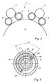
- An inking unit 1 of a rotary printing machine has i.a. a number (e.g. 2) of rotatably mounted friction rollers 2, each with a drive (not shown) for a lateral movement of the friction roller 2.
- the friction rollers 2 are in frictional engagement with a number (e.g. 4) application rollers 3, which in turn are in contact with the surface of a plate cylinder 4 or printing plates arranged thereon.
- the structure of the application rollers 3 is the same and is therefore only described using an application roller 3.
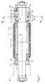
- the application roller 3 has a roller axis 6, which is mounted in roller locks.
- the roller locks are located in a known manner in pivotally mounted levers, so that the application rollers 3 can be switched off from the plate cylinder 4.
- a casing tube 7 with a rubber cover is rotatably and axially displaceable by means of two combined radial-axial bearings 8, 9.
- a lateral stroke of the casing tube 7 is limited on the left side by a stop ring 11 fastened on the roller axis 6.
- a left race 12 of the radial axial bearing 8 abuts a stop surface 13 of the stop ring 11.
- the axial stroke (approx. 7 to 8 mm) is limited by a sliding ring 14.
- a right-hand race 16 of the radial axial bearing 9 abuts against a stop surface 17 of the sliding ring 14.
- the sliding ring 14 is mounted on the roller axis 6 so as to be pivotable and axially displaceable as part of an adjusting device 18.
- the adjusting device 18 also has an adjusting ring 19 and a bearing ring 21.
- the adjusting ring 19 coaxially surrounds the adjusting device 18 and is pivotally and axially displaceably mounted on the sliding ring 14 and the bearing ring 21.
- the pivoting movement of the adjusting ring 19 is limited in the circumferential direction by a radially inwardly oriented first guide pin 22 attached to the adjusting ring 19.
- the guide pin 22 engages in an annular groove 23 in the sliding ring 14.
- a spiral spring 24 e.g. compression spring
- the annular groove 23 is so wide (e.g. 10 mm) that an axial movement of the guide pin 22 is possible.
- the sliding ring 14 and the bearing ring 21 are arranged side by side on the roller axis 6 and are in lateral contact with one another via control surfaces 31, 32.
- the control surface 31 of the sliding ring 14 is aligned axially to the right
- the control surface 32 of the bearing ring 21 is aligned axially to the left.
- the Control surfaces 31, 32 each have a number of mountains 33, 34 and valleys 36, 37.
- a mountain 33 of the control surface 31 of the sliding ring 14 lies against a valley 37 of the control surface 32 of the bearing ring 21 and, conversely, a mountain 34 of the control surface 32 lies against a valley 36 of the control surface 31.
- a mountain 33 of the control surface 31 bears against a mountain 34 of the control surface 32.
- the valleys 36, 37 of the control surfaces 31, 32 have a distance a (e.g. 16 mm) from one another which is twice as large as the stroke h (e.g. 8 mm).
- the races 12, 16 rest against the stop surfaces 13, 17, so that a traversing movement of the roller tube 7 is blocked.
- the roller tube 7 is located outside of a central position relative to the plate cylinder 4.
- the adjusting device 18 is arranged on both sides of the roller axis 6 (in this case the bearing ring 11 is omitted), it is of course also possible to fix the casing tube 7 in the central position.
- the control surfaces 31, 32 would of course have to be changed such that a height distance between mountain 33, 34 and valley 36, 37 is halved.
- the collar 19 can be provided with known actuators, so that an automatic adjustment or remote adjustment is made possible.
- the adjusting ring 19 In order to move the sliding ring 14 or the roller tube 7 from the traversing position "I" to the switch-off position "O", the adjusting ring 19 must be rotated by an angle ⁇ (eg 45 o ) and then by a small distance (eg 5 mm) to the left (Fig. 5,6).
- the guide pin 27 slides upward in the guide groove 28 and engages in the axially extending portion 30 of the groove 28.
- the guide pin 22 slides upward in the annular groove 23 and takes the sliding block 25 and the spiral spring 24 supported thereon with it.
- the coil spring 24 acts without significant bias on the stop 26 and rotates the sliding ring 14. This is supported with its control surface 31 on the control surface 32 of the bearing ring 21 and is thereby shifted axially to the left in the switch-off position "O".
- the sliding ring 14 tends to perform a pivoting movement and to move axially to the left via the control surfaces 31, 32. Therefore, the stop surface 17 of the sliding ring 14 follows the race 16 when it moves entrained by the distributor roller 2 to the left and fixes the casing tube 7 in the switch-off position "O" when the mountain 33 abuts the mountain 34 of the control surfaces 31, 32.
- the adjusting ring 19 is first shifted axially to the right and then pivoted back by the angle ⁇ .
- the guide pin 22 moves into an axially extending part 39 of the annular groove 23 and takes the sliding ring 14 with the pivoting movement of the adjusting ring 19, whereby it is supported on a bolt 38 fastened to the sliding ring 14 until the mountain 33 on the valley 37 and the mountain 34 abuts the valley 36.
- a stop 41 protrudes into the annular groove 23 and prevents the sliding block 25 from blocking the annular groove 23 in the region of the portion 39.
Landscapes
- Inking, Control Or Cleaning Of Printing Machines (AREA)
- Coating Apparatus (AREA)
Priority Applications (1)
| Application Number | Priority Date | Filing Date | Title |
|---|---|---|---|
| EP95103752A EP0668163B1 (de) | 1989-09-20 | 1990-09-17 | Changierende Auftragwalze |
Applications Claiming Priority (2)
| Application Number | Priority Date | Filing Date | Title |
|---|---|---|---|
| DE3931291A DE3931291C1 (enExample) | 1989-09-20 | 1989-09-20 | |
| DE3931291 | 1989-09-20 |
Related Child Applications (2)
| Application Number | Title | Priority Date | Filing Date |
|---|---|---|---|
| EP95103752.2 Division-Into | 1990-09-17 | ||
| EP95103752A Division EP0668163B1 (de) | 1989-09-20 | 1990-09-17 | Changierende Auftragwalze |
Publications (3)
| Publication Number | Publication Date |
|---|---|
| EP0418778A2 EP0418778A2 (de) | 1991-03-27 |
| EP0418778A3 EP0418778A3 (en) | 1991-07-31 |
| EP0418778B1 true EP0418778B1 (de) | 1996-04-10 |
Family
ID=6389754
Family Applications (2)
| Application Number | Title | Priority Date | Filing Date |
|---|---|---|---|
| EP90117853A Expired - Lifetime EP0418778B1 (de) | 1989-09-20 | 1990-09-17 | Changierende Auftragwalze |
| EP95103752A Expired - Lifetime EP0668163B1 (de) | 1989-09-20 | 1990-09-17 | Changierende Auftragwalze |
Family Applications After (1)
| Application Number | Title | Priority Date | Filing Date |
|---|---|---|---|
| EP95103752A Expired - Lifetime EP0668163B1 (de) | 1989-09-20 | 1990-09-17 | Changierende Auftragwalze |
Country Status (7)
| Country | Link |
|---|---|
| US (1) | US5119726A (enExample) |
| EP (2) | EP0418778B1 (enExample) |
| JP (1) | JPH07102690B2 (enExample) |
| CS (1) | CS453490A3 (enExample) |
| DD (1) | DD295803A5 (enExample) |
| DE (3) | DE3931291C1 (enExample) |
| RU (1) | RU1836236C (enExample) |
Cited By (1)
| Publication number | Priority date | Publication date | Assignee | Title |
|---|---|---|---|---|
| DE102005015868B4 (de) * | 2004-04-08 | 2016-12-22 | Heidelberger Druckmaschinen Ag | Druckmaschine |
Families Citing this family (14)
| Publication number | Priority date | Publication date | Assignee | Title |
|---|---|---|---|---|
| DE4112158C2 (de) * | 1991-04-13 | 1994-11-10 | Roland Man Druckmasch | Vorrichtung zur Verstellung des axialen Hubes einer Walze einer Druckmaschine |
| DE4113491A1 (de) * | 1991-04-25 | 1992-10-29 | Koenig & Bauer Ag | Verreibwalze fuer druckmaschinen |
| DE4140048C2 (de) * | 1991-12-05 | 1995-09-21 | Roland Man Druckmasch | Farbwerk einer Druckmaschine, insbesondere Bogenoffsetdruckmaschine |
| US5489931A (en) * | 1994-05-26 | 1996-02-06 | Hewlett-Packard Company | Fluid delivery system including coiled concentric tubes |
| US5632203A (en) * | 1995-06-14 | 1997-05-27 | Quad Graphics, Inc. | Anti-ghosting roller |
| US5979324A (en) * | 1998-04-15 | 1999-11-09 | Heidelberger Druckmaschinen Ag | Position controller for a rotatable adjuster in a printing press |
| DE10023935B4 (de) * | 2000-05-17 | 2004-10-28 | Koenig & Bauer Ag | Kurzfarbwerk einer Rotationsdruckmaschine |
| DE10118132B4 (de) | 2001-04-11 | 2005-04-14 | Koenig & Bauer Ag | Farbwerk einer Rotationsdruckmaschine |
| DE10142226C1 (de) | 2001-08-29 | 2003-03-27 | Koenig & Bauer Ag | Walze |
| DE102004011317A1 (de) | 2003-03-27 | 2004-10-07 | Heidelberger Druckmaschinen Ag | Bedruckstoffverarbeitungsmaschine, insbesondere Druckmaschine |
| JP4879504B2 (ja) | 2004-04-08 | 2012-02-22 | ハイデルベルガー ドルツクマシーネン アクチエンゲゼルシヤフト | 印刷機 |
| CZ303047B6 (cs) * | 2005-03-15 | 2012-03-14 | Kba-Grafitec S.R.O. | Navalovací válec |
| WO2013113616A2 (en) * | 2012-02-01 | 2013-08-08 | Crown Packaging Technology, Inc. | Container decoration |
| EP3877183A4 (en) | 2018-11-09 | 2022-07-27 | Ball Corporation | METERING ROLLER FOR A DECORATOR'S INK STATION ASSEMBLY AND METHOD OF DECORATING A CONTAINER WITH THE DECOR |
Family Cites Families (9)
| Publication number | Priority date | Publication date | Assignee | Title |
|---|---|---|---|---|
| US1584255A (en) * | 1926-03-04 | 1926-05-11 | Temmen Frank | Ink-distributing roller |
| DE3034644C2 (de) * | 1980-09-13 | 1982-10-07 | M.A.N.- Roland Druckmaschinen AG, 6050 Offenbach | Farbwerk mit changierenden Farbauftragswalzen |
| JPS5793150A (en) * | 1980-12-02 | 1982-06-10 | Dainippon Printing Co Ltd | Chrome roller oscillating apparatus in simultaneously feeding device of damping water and ink |
| DE8330123U1 (de) * | 1983-10-19 | 1984-01-12 | Heidelberger Druckmaschinen Ag, 6900 Heidelberg | Farbwerk fuer druckmaschinen |
| US4509426A (en) * | 1983-10-21 | 1985-04-09 | Hardin Philip J | Autoreversing dual axial speed ink roller |
| DD242029A1 (de) * | 1985-10-31 | 1987-01-14 | Polygraph Leipzig | Vorrichtung zum wahlweisen axialen bewegen von farbauftragwalzen |
| DE3638826A1 (de) * | 1986-11-13 | 1988-05-26 | Roland Man Druckmasch | Lagerung fuer changierende auftragwalzen von druckmaschinen |
| JPH01106228U (enExample) * | 1988-01-07 | 1989-07-18 | ||
| DE3800658A1 (de) * | 1988-01-13 | 1989-07-27 | Kotterer Grafotec | Vorrichtung zum auftragen von farbe und/oder feuchtmittel auf eine druckform |
-
1989
- 1989-09-20 DE DE3931291A patent/DE3931291C1/de not_active Revoked
-
1990
- 1990-09-04 US US07/576,832 patent/US5119726A/en not_active Expired - Fee Related
- 1990-09-17 EP EP90117853A patent/EP0418778B1/de not_active Expired - Lifetime
- 1990-09-17 DE DE59010272T patent/DE59010272D1/de not_active Expired - Fee Related
- 1990-09-17 EP EP95103752A patent/EP0668163B1/de not_active Expired - Lifetime
- 1990-09-17 DE DE59010869T patent/DE59010869D1/de not_active Expired - Fee Related
- 1990-09-18 CS CS904534A patent/CS453490A3/cs unknown
- 1990-09-18 DD DD90344081A patent/DD295803A5/de not_active IP Right Cessation
- 1990-09-19 JP JP2247645A patent/JPH07102690B2/ja not_active Expired - Lifetime
- 1990-09-19 RU SU904831024A patent/RU1836236C/ru active
Cited By (1)
| Publication number | Priority date | Publication date | Assignee | Title |
|---|---|---|---|---|
| DE102005015868B4 (de) * | 2004-04-08 | 2016-12-22 | Heidelberger Druckmaschinen Ag | Druckmaschine |
Also Published As
| Publication number | Publication date |
|---|---|
| EP0668163A2 (de) | 1995-08-23 |
| US5119726A (en) | 1992-06-09 |
| DD295803A5 (de) | 1991-11-14 |
| EP0668163B1 (de) | 1999-04-21 |
| DE59010272D1 (de) | 1996-05-15 |
| DE59010869D1 (de) | 1999-05-27 |
| EP0668163A3 (de) | 1996-07-24 |
| JPH03118157A (ja) | 1991-05-20 |
| JPH07102690B2 (ja) | 1995-11-08 |
| CS453490A3 (en) | 1992-09-16 |
| EP0418778A3 (en) | 1991-07-31 |
| EP0418778A2 (de) | 1991-03-27 |
| RU1836236C (ru) | 1993-08-23 |
| DE3931291C1 (enExample) | 1991-04-18 |
Similar Documents
| Publication | Publication Date | Title |
|---|---|---|
| EP0418778B1 (de) | Changierende Auftragwalze | |
| DE4411516A1 (de) | Spielfreies Kurvengetriebe | |
| EP0396904A2 (de) | Vorrichtung zum Anstellen und Abheben eines auf einen Formzylinder wirkenden Gegendruckzylinders | |
| DE2611285C2 (de) | Schrittschalteinrichtung für Drehelemente bei Werkzeugmaschinen | |
| EP0442265B1 (de) | Klemmvorrichtung für ein axial verschiebbares Stellglied zur Greiferumsteuerung an einem Greiferzylinder einer Bogenrotationsdruckmaschine | |
| DE3414639C2 (enExample) | ||
| DE3245230A1 (de) | Festigkeitsverstelleinrichtung an flachstrickmaschinen | |
| EP0240877B1 (de) | Teleskopabdeckung | |
| CH639709A5 (de) | Rotations-schaftmaschine. | |
| EP0498045A1 (de) | Vorrichtung zur Höhenverstellung von Walzen | |
| DE1455150C3 (de) | Spurwechselradsatz für Schienenfahrzeuge mit axial auf der Achswelle verschiebbaren Schienenrädern | |
| DE3832060A1 (de) | Streckwerk fuer spinnereimaschinen | |
| DE60005496T2 (de) | Differentialsperre | |
| EP0414958B1 (de) | Spanneinrichtung an Werkzeugmaschinen | |
| DE1025489B (de) | Schalt- oder Regelgeraet | |
| DE9007492U1 (de) | Rollen-Reibschraubantrieb | |
| EP0377857B1 (de) | Vorrichtung zur elektrischen Absicherung einer Klemmvorrichtung in einer Bogenführungstrommel von Druckmaschinen | |
| DE1510921B2 (de) | Spindel fuer textilmaschinen | |
| DE3236236C2 (enExample) | ||
| EP0013746A2 (de) | Vorrichtung zum Einspannen von Werkstücken | |
| DE8915508U1 (de) | Changierende Auftragswalze | |
| DE19739571B4 (de) | Stellvorrichtung für eine Höhenverstellung von diametral gegenüberliegend angeordneten Greiferaufschlagleisten an bogenführenden Zylindern von Druckmaschinen | |
| DE3932991C2 (enExample) | ||
| DE2656283C2 (de) | Vorrichtung zum Einstellen eines Summentypenträgers an Schreib- oder ähnlichen Büromaschinen | |
| AT347248B (de) | Antriebssystem |
Legal Events
| Date | Code | Title | Description |
|---|---|---|---|
| PUAI | Public reference made under article 153(3) epc to a published international application that has entered the european phase |
Free format text: ORIGINAL CODE: 0009012 |
|
| AK | Designated contracting states |
Kind code of ref document: A2 Designated state(s): DE FR GB IT SE |
|
| PUAL | Search report despatched |
Free format text: ORIGINAL CODE: 0009013 |
|
| AK | Designated contracting states |
Kind code of ref document: A3 Designated state(s): DE FR GB IT SE |
|
| 17P | Request for examination filed |
Effective date: 19911010 |
|
| 17Q | First examination report despatched |
Effective date: 19930609 |
|
| RAP1 | Party data changed (applicant data changed or rights of an application transferred) |
Owner name: KOENIG & BAUER-ALBERT AKTIENGESELLSCHAFT |
|
| RAP1 | Party data changed (applicant data changed or rights of an application transferred) |
Owner name: KOENIG & BAUER-ALBERT AKTIENGESELLSCHAFT |
|
| ITF | It: translation for a ep patent filed | ||
| GRAH | Despatch of communication of intention to grant a patent |
Free format text: ORIGINAL CODE: EPIDOS IGRA |
|
| GRAA | (expected) grant |
Free format text: ORIGINAL CODE: 0009210 |
|
| AK | Designated contracting states |
Kind code of ref document: B1 Designated state(s): DE FR GB IT SE |
|
| XX | Miscellaneous (additional remarks) |
Free format text: TEILANMELDUNG 95103752.2. |
|
| ET | Fr: translation filed | ||
| REF | Corresponds to: |
Ref document number: 59010272 Country of ref document: DE Date of ref document: 19960515 |
|
| GBT | Gb: translation of ep patent filed (gb section 77(6)(a)/1977) |
Effective date: 19960508 |
|
| PLBE | No opposition filed within time limit |
Free format text: ORIGINAL CODE: 0009261 |
|
| STAA | Information on the status of an ep patent application or granted ep patent |
Free format text: STATUS: NO OPPOSITION FILED WITHIN TIME LIMIT |
|
| 26N | No opposition filed | ||
| PGFP | Annual fee paid to national office [announced via postgrant information from national office to epo] |
Ref country code: GB Payment date: 20000821 Year of fee payment: 11 |
|
| PGFP | Annual fee paid to national office [announced via postgrant information from national office to epo] |
Ref country code: FR Payment date: 20000918 Year of fee payment: 11 |
|
| PGFP | Annual fee paid to national office [announced via postgrant information from national office to epo] |
Ref country code: SE Payment date: 20000921 Year of fee payment: 11 |
|
| PGFP | Annual fee paid to national office [announced via postgrant information from national office to epo] |
Ref country code: DE Payment date: 20000929 Year of fee payment: 11 |
|
| PG25 | Lapsed in a contracting state [announced via postgrant information from national office to epo] |
Ref country code: GB Free format text: LAPSE BECAUSE OF NON-PAYMENT OF DUE FEES Effective date: 20010917 |
|
| PG25 | Lapsed in a contracting state [announced via postgrant information from national office to epo] |
Ref country code: SE Free format text: LAPSE BECAUSE OF NON-PAYMENT OF DUE FEES Effective date: 20010918 |
|
| REG | Reference to a national code |
Ref country code: GB Ref legal event code: IF02 |
|
| EUG | Se: european patent has lapsed |
Ref document number: 90117853.3 |
|
| GBPC | Gb: european patent ceased through non-payment of renewal fee |
Effective date: 20010917 |
|
| PG25 | Lapsed in a contracting state [announced via postgrant information from national office to epo] |
Ref country code: FR Free format text: LAPSE BECAUSE OF NON-PAYMENT OF DUE FEES Effective date: 20020531 |
|
| PG25 | Lapsed in a contracting state [announced via postgrant information from national office to epo] |
Ref country code: DE Free format text: LAPSE BECAUSE OF NON-PAYMENT OF DUE FEES Effective date: 20020601 |
|
| REG | Reference to a national code |
Ref country code: FR Ref legal event code: ST |
|
| PG25 | Lapsed in a contracting state [announced via postgrant information from national office to epo] |
Ref country code: IT Free format text: LAPSE BECAUSE OF NON-PAYMENT OF DUE FEES;WARNING: LAPSES OF ITALIAN PATENTS WITH EFFECTIVE DATE BEFORE 2007 MAY HAVE OCCURRED AT ANY TIME BEFORE 2007. THE CORRECT EFFECTIVE DATE MAY BE DIFFERENT FROM THE ONE RECORDED. Effective date: 20050917 |