EP0416638A2 - Tringle pour bandage pneumatique - Google Patents
Tringle pour bandage pneumatique Download PDFInfo
- Publication number
- EP0416638A2 EP0416638A2 EP90117238A EP90117238A EP0416638A2 EP 0416638 A2 EP0416638 A2 EP 0416638A2 EP 90117238 A EP90117238 A EP 90117238A EP 90117238 A EP90117238 A EP 90117238A EP 0416638 A2 EP0416638 A2 EP 0416638A2
- Authority
- EP
- European Patent Office
- Prior art keywords
- strength members
- core
- winding
- winding spool
- bead core
- Prior art date
- Legal status (The legal status is an assumption and is not a legal conclusion. Google has not performed a legal analysis and makes no representation as to the accuracy of the status listed.)
- Withdrawn
Links
- 239000011324 bead Substances 0.000 title claims abstract description 47
- 238000004804 winding Methods 0.000 claims abstract description 40
- 238000000034 method Methods 0.000 claims abstract description 9
- 238000004519 manufacturing process Methods 0.000 claims description 5
- 238000001125 extrusion Methods 0.000 claims description 3
- 230000003139 buffering effect Effects 0.000 claims description 2
- 238000005507 spraying Methods 0.000 claims description 2
- 230000003014 reinforcing effect Effects 0.000 claims 2
- 229920000271 Kevlar® Polymers 0.000 claims 1
- 239000004760 aramid Substances 0.000 claims 1
- 229920006231 aramid fiber Polymers 0.000 claims 1
- 239000004761 kevlar Substances 0.000 claims 1
- 239000010410 layer Substances 0.000 description 40
- 230000002787 reinforcement Effects 0.000 description 12
- 238000010073 coating (rubber) Methods 0.000 description 3
- 239000012792 core layer Substances 0.000 description 2
- 238000010276 construction Methods 0.000 description 1
- 230000007547 defect Effects 0.000 description 1
- 238000010616 electrical installation Methods 0.000 description 1
- 238000005538 encapsulation Methods 0.000 description 1
- 238000005516 engineering process Methods 0.000 description 1
- 230000002349 favourable effect Effects 0.000 description 1
- 230000005484 gravity Effects 0.000 description 1
- 238000009413 insulation Methods 0.000 description 1
- 239000002356 single layer Substances 0.000 description 1
- 238000013517 stratification Methods 0.000 description 1
- 230000009897 systematic effect Effects 0.000 description 1
Images

Classifications
-
- B—PERFORMING OPERATIONS; TRANSPORTING
- B60—VEHICLES IN GENERAL
- B60C—VEHICLE TYRES; TYRE INFLATION; TYRE CHANGING; CONNECTING VALVES TO INFLATABLE ELASTIC BODIES IN GENERAL; DEVICES OR ARRANGEMENTS RELATED TO TYRES
- B60C15/00—Tyre beads, e.g. ply turn-up or overlap
- B60C15/04—Bead cores
Definitions
- the invention relates to a bead core for pneumatic vehicle tires consisting of several spirally wound layers of strength members lying next to one another.
- a bead core for pneumatic vehicle tires consisting of several spirally wound layers of strength members lying next to one another.
- the spooled cores in question here have largely prevailed because of their value for money and the great design freedom of the core cross-section.
- an endless layer is first formed of strength members lying next to one another and overmoulded with rubber. Apart from the other dimensions, in particular the much denser position of the strength members (wires), such a layer bears in principle a similarity to a flat cable from the electrical installation, the insulation being the analogue for the rubber.
- the number of adjacent strength members of a layer is between three and nine. From such a layer, a core is built up in such a way that the end of the layer is attached to the outer surface of a cylindrical coil and the layer is then wound up to several turns, separated and the end of the layer is pressed on. Depending on the tire size, three to eight turns are applied; Analogous to the language used in the description of carcasses, the individual turns of a bead core produced in this way are mostly referred to as "layers" - as is also the case in this application. The bead cores produced in the manner described are called Pierce cores in the tire technical language.
- the Pierce cores have the disadvantage that the inner radius of the bead core changes discontinuously at the beginning of the first turn by the thickness of a layer. This inconsistent radius fluctuation continues to a certain extent into the carcass and leads to a systematic runout. Although this error can be kept sufficiently small by a particularly skillful handling of the layers on the tire building machine, it still complicates the automation of the carcass structure. Naturally, this source of error becomes smaller if the layer thickness is reduced and the number of layers is increased; however, the bead core structure becomes more expensive and, if this development direction is taken to the extreme, is susceptible to warping.
- the object of the invention is to provide a bead core which, while maintaining the particularly economical winding of rubber-coated reinforcement layers and without specific (manual) adjustment of the length of the carcass ply envelope around the bead core, enables a pneumatic vehicle tire with improved concentricity.
- each of the layers of the bead core has a larger radial than axial component of its extension.
- the reinforcement layers of the bead core lie in such a way that in the fully vulcanized and assembled tire these layers are parallel to the rim flanges.
- the rim flanges of most rims have only a slight taper, ie they extend essentially in the radial direction, while their extension in the axial direction is of minor importance.
- the Bead core layers extend essentially in the radial direction with a possibly small extension component in the axial direction. With such an arrangement, the spiral start and the spiral end are essentially axially spaced from one another.
- the individual layers When cutting through a bead core according to the invention, the individual layers no longer appear as structures stacked on top of one another, as in the prior art, but rather as structures standing upright and arranged side by side.
- the bead cores according to the invention also each have a discontinuity at the beginning and end of the spiral, but these discontinuities are now essentially offset in the axial direction and no longer in the radial direction and therefore influence the extent of the carcass which extends radially away from the bead core practically not;
- the bead cores according to the invention preferably also contain wire as a reinforcement, as is known per se in the prior art. This enables economical production with favorable rigidity.
- the process described below is recommended: First, as many individual strength members as are supposed to lie in an upright position according to the invention are continuously extrusion-coated with rubber. Each of these overmolded individual reinforcement passes through a separate magazine, which serves in a manner known per se for buffering between the continuously operating spraying system and the discontinuously operating core winding unit.
- the core winding begins with the fact that as many strength members as one (upright) layer is to be attached to one another on a winding spool, the winding spool receiving the strength members on a flanged wheel which is delimited radially inward by a rotationally symmetrical stop, the outer dimensions of which corresponds to the radially inner contour of the core to be wound.
- the winding spool is rotated as often as the core to be wound should have essentially axially adjacent (upright) layers.
- the speed at which the various reinforcement elements are pulled out of their respective magazines differs here because the reinforcement elements located further outwards in an upright position require a greater circumferential length in accordance with their larger radius.
- the special feature of this process is that the reinforcements of a layer are not extrusion-coated with rubber, but individually, are stored individually in separate magazines and are assembled into a layer only immediately before the winding drum or even only on the winding drum.
- the novel process problem is solved in a particularly reliable manner, that the strength members of a layer require a different withdrawal speed from the extruder used for rubber encapsulation in accordance with the differences in their radius.
- This process problem exists in the manufacture of the known Pierce cores, since there all strength members of an (only axially extending) position with respect to the tire rotation axis have the same radius, so they only need the same withdrawal speed from the (common) extruder.
- the outer contour of the rubber coating of the strength members has the shape of a parallelogram or square, that is to say deviates from the usual circular cross-section. It is recommended that the four sides be spherical.
- a winding coil as device for carrying out the previously described method for producing bead cores according to the invention expediently has a perpendicular axis of rotation.
- the winding spool has its simplest geometric shape when the rotationally symmetrical stop, which molds the side of the bead core to be wound, which faces radially inward in the finished tire, is designed as the outer surface of a cylinder.
- the rotationally symmetrical stop which molds the side of the bead core to be wound, which faces radially inward in the finished tire, is designed as the outer surface of a cylinder.
- the rotationally symmetrical stop preferably has the shape of a truncated cone with an angle between the outer surface and the axis of rotation between 5 o and 20 o depending on the type of rim for which the tire is intended.
- This parallelism has so far only been achieved with bead cores which are wound from a single wire, that is, not from wire.
- these known cores wound from a single wire had the disadvantage that their winding took up a lot of time; For example, a 6 x 6 wire package required six times the winding time as for the widely used Pierce core.
- bead cores that conform to the rim contour can be produced just as quickly as the widespread Pierce cores that do not conform to the rim contour.
- the rim contour Justice is also achieved in the area of the rim flange characterized in that the flanged disc cross-section of the reel spool in accordance with the rim cross-section, intended for the tire with the inventive bead core, is o o inclined by 80 to 85 with respect to the axis of rotation .
- the throat between the flanged disc and the stop of the winding spool has an angle equal to or greater than 100 o .
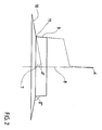
- FIG. 1 shows a bead core 2 according to the invention in a perspective half-section.
- the bead core 2 consists over the largest part of its circumference from five layers 3.1 to 3.5; in the small circumferential area, which is also referred to as an overlap, between the spiral start 5 and the spiral end 6, the core has six layers with the help of the end position 3.6. All layers 3 consist of five wires 4.
- the core winding begins with stitching the beginning of the layer onto the flanged wheel 10, the radially innermost point of the first layer in the throat 11 supporting the stop surface 9.
- the flanged disk 10 is inclined in this embodiment by 80 o with respect to the axis of rotation. 8
- the invention is not limited to the illustrated domesticsbei games;
- the essence of bead cores according to the invention is only that their radially inner side is essentially formed by the narrow end faces of upright, wound layers, so that the defects at the winding start (and winding end) from the radially inner (or radially outer) side, where they The Pierce core lies (is) on both axial sides of the bead cores.
- the Pierce core only has one fault point for the concentricity of the carcass, namely the start of the winding, bead cores according to the invention, however, two fault points, namely the start and end of the winding, both of which touch the carcass, but the influence of these fault points is orders of magnitude less, from which the superior concentricity of pneumatic vehicle tires with bead cores according to the invention results.
- Bead cores according to the invention can be used both with single-layer and multi-layer carcasses and are particularly suitable for the radial carcasses prevailing today. The further tire construction does not require any changes.
Landscapes
- Engineering & Computer Science (AREA)
- Mechanical Engineering (AREA)
- Tires In General (AREA)
- Tyre Moulding (AREA)
Applications Claiming Priority (2)
| Application Number | Priority Date | Filing Date | Title |
|---|---|---|---|
| DE19893929975 DE3929975A1 (de) | 1989-09-08 | 1989-09-08 | Wulstkern fuer fahrzeugluftreifen |
| DE3929975 | 1989-09-08 |
Publications (2)
| Publication Number | Publication Date |
|---|---|
| EP0416638A2 true EP0416638A2 (fr) | 1991-03-13 |
| EP0416638A3 EP0416638A3 (en) | 1991-07-31 |
Family
ID=6388974
Family Applications (1)
| Application Number | Title | Priority Date | Filing Date |
|---|---|---|---|
| EP19900117238 Withdrawn EP0416638A3 (en) | 1989-09-08 | 1990-09-07 | Bead core for pneumatic tyre |
Country Status (3)
| Country | Link |
|---|---|
| EP (1) | EP0416638A3 (fr) |
| JP (1) | JPH03148313A (fr) |
| DE (1) | DE3929975A1 (fr) |
Cited By (4)
| Publication number | Priority date | Publication date | Assignee | Title |
|---|---|---|---|---|
| EP0628434A1 (fr) * | 1993-06-07 | 1994-12-14 | Continental Aktiengesellschaft | Bandage pneumatique pour véhicule |
| EP0642936A1 (fr) * | 1993-09-14 | 1995-03-15 | BRIDGESTONE/FIRESTONE, Inc. | Bandage pneumatique ayant des tringles enroulées en sens opposé |
| GB2317150A (en) * | 1996-08-12 | 1998-03-18 | Bridgestone Corp | Tire bead core |
| EP0899132A1 (fr) * | 1997-08-27 | 1999-03-03 | Bridgestone Corporation | Bandages pneumatiques |
Families Citing this family (1)
| Publication number | Priority date | Publication date | Assignee | Title |
|---|---|---|---|---|
| DE29518920U1 (de) | 1995-11-29 | 1997-03-27 | Hahn GmbH & Co, 58769 Nachrodt-Wiblingwerde | Wulstkern für Fahrzeugreifen |
Family Cites Families (7)
| Publication number | Priority date | Publication date | Assignee | Title |
|---|---|---|---|---|
| US1503985A (en) * | 1923-03-19 | 1924-08-05 | William G Corson | Grommet |
| DE2409816A1 (de) * | 1974-03-01 | 1975-09-11 | Continental Gummi Werke Ag | Fahrzeugluftreifen |
| FR2456610A1 (fr) * | 1979-02-19 | 1980-12-12 | Michelin & Cie | Procede de fabrication de tringles pour bourrelets de pneumatiques |
| DE3613349A1 (de) * | 1986-04-19 | 1987-10-22 | Continental Gummi Werke Ag | Kernring fuer die wuelste von luftreifen |
| DE3613350A1 (de) * | 1986-04-19 | 1987-10-22 | Continental Gummi Werke Ag | Kernring fuer die wuelste von luftreifen |
| US4820563A (en) * | 1987-08-13 | 1989-04-11 | National-Standard Company | Tire bead assembly |
| DE3738446A1 (de) * | 1987-11-12 | 1989-05-24 | Uniroyal Englebert Gmbh | Fahrzeugluftreifen |
-
1989
- 1989-09-08 DE DE19893929975 patent/DE3929975A1/de not_active Withdrawn
-
1990
- 1990-09-07 EP EP19900117238 patent/EP0416638A3/de not_active Withdrawn
- 1990-09-07 JP JP2235988A patent/JPH03148313A/ja active Pending
Cited By (6)
| Publication number | Priority date | Publication date | Assignee | Title |
|---|---|---|---|---|
| EP0628434A1 (fr) * | 1993-06-07 | 1994-12-14 | Continental Aktiengesellschaft | Bandage pneumatique pour véhicule |
| EP0642936A1 (fr) * | 1993-09-14 | 1995-03-15 | BRIDGESTONE/FIRESTONE, Inc. | Bandage pneumatique ayant des tringles enroulées en sens opposé |
| GB2317150A (en) * | 1996-08-12 | 1998-03-18 | Bridgestone Corp | Tire bead core |
| US5871603A (en) * | 1996-08-12 | 1999-02-16 | Bridgestone Corporation | Pneumatic tires with organic or inorganic fiber cord bead core |
| GB2317150B (en) * | 1996-08-12 | 2000-08-30 | Bridgestone Corp | Pneumatic tires |
| EP0899132A1 (fr) * | 1997-08-27 | 1999-03-03 | Bridgestone Corporation | Bandages pneumatiques |
Also Published As
| Publication number | Publication date |
|---|---|
| EP0416638A3 (en) | 1991-07-31 |
| DE3929975A1 (de) | 1991-03-21 |
| JPH03148313A (ja) | 1991-06-25 |
Similar Documents
| Publication | Publication Date | Title |
|---|---|---|
| DE1735017C3 (de) | Einteilige Wickelhülse aus Kunststoff, insbesondere zur Aufnahme von Garnwicklungen | |
| DE856517C (de) | Verfahren zur Herstellung von Fahrzeugluftreifen nach dem Flachbandverfahren | |
| DE1283691B (de) | Fahrzeugluftreifen | |
| DE1505112B1 (de) | Verfahren zur Herstellung eines Fahrzeugluftreifens | |
| EP0622251B1 (fr) | Bandage non-pneumatique | |
| DE69830826T2 (de) | Verbesserte Luftreifenkonstruktion und Verfahren zur Herstellung | |
| DE2204746A1 (de) | Schlauchloser fahrzeugluftreifen | |
| DE4208705A1 (de) | Herstellverfahren fuer einen guertel | |
| EP0537780A2 (fr) | Procédé de fabrication d'une bande enroulée pour pneumatique | |
| DE2308844A1 (de) | Verfahren zur herstellung einer luftreifen-scheitelbewehrung und nach dem verfahren hergestellter luftreifen | |
| DE3878469T2 (de) | Wulstkern. | |
| DE69113638T2 (de) | Luftreifen für schwerlasten mit hohem druck. | |
| DE3873594T2 (de) | Luftreifenwulst fuer fahrzeuge. | |
| EP0416638A2 (fr) | Tringle pour bandage pneumatique | |
| EP0052737B1 (fr) | Bandage pneumatique | |
| DE3227138C2 (fr) | ||
| DE2439092A1 (de) | Luftreifen | |
| EP1888325B1 (fr) | Procede de production d'un pneu de vehicule | |
| DE3738446A1 (de) | Fahrzeugluftreifen | |
| DE2603349A1 (de) | Luftreifen | |
| DE2505741C3 (de) | Wulstkern für Fahrzeugluftreifen | |
| DE69504017T2 (de) | Wulstkern für Luftreifen | |
| EP1718480A1 (fr) | Pneu de vehicule et procede pour sa production | |
| DE69905269T2 (de) | Verfahren zur herstellung eines kernlosen luftreifens | |
| DE2261475A1 (de) | Luftreifen |
Legal Events
| Date | Code | Title | Description |
|---|---|---|---|
| PUAI | Public reference made under article 153(3) epc to a published international application that has entered the european phase |
Free format text: ORIGINAL CODE: 0009012 |
|
| AK | Designated contracting states |
Kind code of ref document: A2 Designated state(s): DE ES FR GB IT |
|
| PUAL | Search report despatched |
Free format text: ORIGINAL CODE: 0009013 |
|
| AK | Designated contracting states |
Kind code of ref document: A3 Designated state(s): DE ES FR GB IT |
|
| 17P | Request for examination filed |
Effective date: 19910624 |
|
| 17Q | First examination report despatched |
Effective date: 19930726 |
|
| RAP1 | Party data changed (applicant data changed or rights of an application transferred) |
Owner name: CONTINENTAL AKTIENGESELLSCHAFT |
|
| STAA | Information on the status of an ep patent application or granted ep patent |
Free format text: STATUS: THE APPLICATION IS DEEMED TO BE WITHDRAWN |
|
| 18D | Application deemed to be withdrawn |
Effective date: 19940317 |