EP0416638A2 - Bead core for pneumatic tyre - Google Patents
Bead core for pneumatic tyre Download PDFInfo
- Publication number
- EP0416638A2 EP0416638A2 EP90117238A EP90117238A EP0416638A2 EP 0416638 A2 EP0416638 A2 EP 0416638A2 EP 90117238 A EP90117238 A EP 90117238A EP 90117238 A EP90117238 A EP 90117238A EP 0416638 A2 EP0416638 A2 EP 0416638A2
- Authority
- EP
- European Patent Office
- Prior art keywords
- strength members
- core
- winding
- winding spool
- bead core
- Prior art date
- Legal status (The legal status is an assumption and is not a legal conclusion. Google has not performed a legal analysis and makes no representation as to the accuracy of the status listed.)
- Withdrawn
Links
Images

Classifications
-
- B—PERFORMING OPERATIONS; TRANSPORTING
- B60—VEHICLES IN GENERAL
- B60C—VEHICLE TYRES; TYRE INFLATION; TYRE CHANGING; CONNECTING VALVES TO INFLATABLE ELASTIC BODIES IN GENERAL; DEVICES OR ARRANGEMENTS RELATED TO TYRES
- B60C15/00—Tyre beads, e.g. ply turn-up or overlap
- B60C15/04—Bead cores
Definitions
- the invention relates to a bead core for pneumatic vehicle tires consisting of several spirally wound layers of strength members lying next to one another.
- a bead core for pneumatic vehicle tires consisting of several spirally wound layers of strength members lying next to one another.
- the spooled cores in question here have largely prevailed because of their value for money and the great design freedom of the core cross-section.
- an endless layer is first formed of strength members lying next to one another and overmoulded with rubber. Apart from the other dimensions, in particular the much denser position of the strength members (wires), such a layer bears in principle a similarity to a flat cable from the electrical installation, the insulation being the analogue for the rubber.
- the number of adjacent strength members of a layer is between three and nine. From such a layer, a core is built up in such a way that the end of the layer is attached to the outer surface of a cylindrical coil and the layer is then wound up to several turns, separated and the end of the layer is pressed on. Depending on the tire size, three to eight turns are applied; Analogous to the language used in the description of carcasses, the individual turns of a bead core produced in this way are mostly referred to as "layers" - as is also the case in this application. The bead cores produced in the manner described are called Pierce cores in the tire technical language.
- the Pierce cores have the disadvantage that the inner radius of the bead core changes discontinuously at the beginning of the first turn by the thickness of a layer. This inconsistent radius fluctuation continues to a certain extent into the carcass and leads to a systematic runout. Although this error can be kept sufficiently small by a particularly skillful handling of the layers on the tire building machine, it still complicates the automation of the carcass structure. Naturally, this source of error becomes smaller if the layer thickness is reduced and the number of layers is increased; however, the bead core structure becomes more expensive and, if this development direction is taken to the extreme, is susceptible to warping.
- the object of the invention is to provide a bead core which, while maintaining the particularly economical winding of rubber-coated reinforcement layers and without specific (manual) adjustment of the length of the carcass ply envelope around the bead core, enables a pneumatic vehicle tire with improved concentricity.
- each of the layers of the bead core has a larger radial than axial component of its extension.
- the reinforcement layers of the bead core lie in such a way that in the fully vulcanized and assembled tire these layers are parallel to the rim flanges.
- the rim flanges of most rims have only a slight taper, ie they extend essentially in the radial direction, while their extension in the axial direction is of minor importance.
- the Bead core layers extend essentially in the radial direction with a possibly small extension component in the axial direction. With such an arrangement, the spiral start and the spiral end are essentially axially spaced from one another.
- the individual layers When cutting through a bead core according to the invention, the individual layers no longer appear as structures stacked on top of one another, as in the prior art, but rather as structures standing upright and arranged side by side.
- the bead cores according to the invention also each have a discontinuity at the beginning and end of the spiral, but these discontinuities are now essentially offset in the axial direction and no longer in the radial direction and therefore influence the extent of the carcass which extends radially away from the bead core practically not;
- the bead cores according to the invention preferably also contain wire as a reinforcement, as is known per se in the prior art. This enables economical production with favorable rigidity.
- the process described below is recommended: First, as many individual strength members as are supposed to lie in an upright position according to the invention are continuously extrusion-coated with rubber. Each of these overmolded individual reinforcement passes through a separate magazine, which serves in a manner known per se for buffering between the continuously operating spraying system and the discontinuously operating core winding unit.
- the core winding begins with the fact that as many strength members as one (upright) layer is to be attached to one another on a winding spool, the winding spool receiving the strength members on a flanged wheel which is delimited radially inward by a rotationally symmetrical stop, the outer dimensions of which corresponds to the radially inner contour of the core to be wound.
- the winding spool is rotated as often as the core to be wound should have essentially axially adjacent (upright) layers.
- the speed at which the various reinforcement elements are pulled out of their respective magazines differs here because the reinforcement elements located further outwards in an upright position require a greater circumferential length in accordance with their larger radius.
- the special feature of this process is that the reinforcements of a layer are not extrusion-coated with rubber, but individually, are stored individually in separate magazines and are assembled into a layer only immediately before the winding drum or even only on the winding drum.
- the novel process problem is solved in a particularly reliable manner, that the strength members of a layer require a different withdrawal speed from the extruder used for rubber encapsulation in accordance with the differences in their radius.
- This process problem exists in the manufacture of the known Pierce cores, since there all strength members of an (only axially extending) position with respect to the tire rotation axis have the same radius, so they only need the same withdrawal speed from the (common) extruder.
- the outer contour of the rubber coating of the strength members has the shape of a parallelogram or square, that is to say deviates from the usual circular cross-section. It is recommended that the four sides be spherical.
- a winding coil as device for carrying out the previously described method for producing bead cores according to the invention expediently has a perpendicular axis of rotation.
- the winding spool has its simplest geometric shape when the rotationally symmetrical stop, which molds the side of the bead core to be wound, which faces radially inward in the finished tire, is designed as the outer surface of a cylinder.
- the rotationally symmetrical stop which molds the side of the bead core to be wound, which faces radially inward in the finished tire, is designed as the outer surface of a cylinder.
- the rotationally symmetrical stop preferably has the shape of a truncated cone with an angle between the outer surface and the axis of rotation between 5 o and 20 o depending on the type of rim for which the tire is intended.
- This parallelism has so far only been achieved with bead cores which are wound from a single wire, that is, not from wire.
- these known cores wound from a single wire had the disadvantage that their winding took up a lot of time; For example, a 6 x 6 wire package required six times the winding time as for the widely used Pierce core.
- bead cores that conform to the rim contour can be produced just as quickly as the widespread Pierce cores that do not conform to the rim contour.
- the rim contour Justice is also achieved in the area of the rim flange characterized in that the flanged disc cross-section of the reel spool in accordance with the rim cross-section, intended for the tire with the inventive bead core, is o o inclined by 80 to 85 with respect to the axis of rotation .
- the throat between the flanged disc and the stop of the winding spool has an angle equal to or greater than 100 o .
- FIG. 1 shows a bead core 2 according to the invention in a perspective half-section.
- the bead core 2 consists over the largest part of its circumference from five layers 3.1 to 3.5; in the small circumferential area, which is also referred to as an overlap, between the spiral start 5 and the spiral end 6, the core has six layers with the help of the end position 3.6. All layers 3 consist of five wires 4.
- the core winding begins with stitching the beginning of the layer onto the flanged wheel 10, the radially innermost point of the first layer in the throat 11 supporting the stop surface 9.
- the flanged disk 10 is inclined in this embodiment by 80 o with respect to the axis of rotation. 8
- the invention is not limited to the illustrated domesticsbei games;
- the essence of bead cores according to the invention is only that their radially inner side is essentially formed by the narrow end faces of upright, wound layers, so that the defects at the winding start (and winding end) from the radially inner (or radially outer) side, where they The Pierce core lies (is) on both axial sides of the bead cores.
- the Pierce core only has one fault point for the concentricity of the carcass, namely the start of the winding, bead cores according to the invention, however, two fault points, namely the start and end of the winding, both of which touch the carcass, but the influence of these fault points is orders of magnitude less, from which the superior concentricity of pneumatic vehicle tires with bead cores according to the invention results.
- Bead cores according to the invention can be used both with single-layer and multi-layer carcasses and are particularly suitable for the radial carcasses prevailing today. The further tire construction does not require any changes.
Abstract
Description
Die Erfindung bezieht sich auf einen Wulstkern für Fahrzeugluftreifen bestehend aus mehreren spiralig aufgespulten Lagen von nebeneinander liegenden Festigkeitsträgern. Neben den sogenannten Kabelkernen, wo die Festigkeitsträger nach verschiedenen Mustern gegeneinander verdrillt sind, haben sich die hier in Rede stehenden gespulten Kerne wegen ihrer Preiswürdigkeit und der großen Gestaltungsfreiheit des Kernquerschnittes weitgehend durchgesetzt. Zur Herstellung dieser Kerntype wird zunächst eine endlose Lage gebildet von nebeneinander liegenden, mit Kautschuk umspritzten Festigkeitsträgern. Abgesehen von den anderen Abmessungen, insbesondere der wesentlich dichteren Stellung der Festigkeitsträger (Drähte) hat eine solche Lage eine prinzipiellle Ähnlichkeit mit einem Flachkabel aus der Elektroinstallation, wobei die Isolation das Analogon für den Kautschuk wäre. Die Anzahl der nebeneinander liegenden Festigkeitsträger einer Lage liegt je nach Reifengröße zwischen drei und neun. Aus einer solchen Lage wird ein Kern in der Weise aufgebaut, daß das Lagenende auf der Mantelfläche einer zylindrischen Spule angeheftet wird und die Lage dann bis auf mehrere Windungen aufgewickelt, abgetrennt und das Lagenende angedrückt wird. Je nach Reifengröße werden drei bis acht Windungen aufgebracht; analog dem Sprachgebrauch in der Beschreibung von Karkassen werden die einzelnen Windungen eines solchermaßen hergestellten Wulstkernes meistens als "Lagen" bezeichnet - so auch in dieser Anmeldung. Die in der beschriebenen Weise hergestelten Wulstkerne heißen in der Reifenfachsprache Pierce-Kerne.The invention relates to a bead core for pneumatic vehicle tires consisting of several spirally wound layers of strength members lying next to one another. In addition to the so-called cable cores, where the strength members are twisted against one another according to different patterns, the spooled cores in question here have largely prevailed because of their value for money and the great design freedom of the core cross-section. To produce this type of core, an endless layer is first formed of strength members lying next to one another and overmoulded with rubber. Apart from the other dimensions, in particular the much denser position of the strength members (wires), such a layer bears in principle a similarity to a flat cable from the electrical installation, the insulation being the analogue for the rubber. Depending on the size of the tire, the number of adjacent strength members of a layer is between three and nine. From such a layer, a core is built up in such a way that the end of the layer is attached to the outer surface of a cylindrical coil and the layer is then wound up to several turns, separated and the end of the layer is pressed on. Depending on the tire size, three to eight turns are applied; Analogous to the language used in the description of carcasses, the individual turns of a bead core produced in this way are mostly referred to as "layers" - as is also the case in this application. The bead cores produced in the manner described are called Pierce cores in the tire technical language.
Neben den erwähnten Vorteilen haftet den Pierce-Kernen der Nachteil an, daß der Innenradius des Wulstkernes sich am Beginn der ersten Windung unstetig um die Dicke einer Lage ändert. Diese unstetige Radiusschwankung setzt sich in einem gewissen Umfang bis in die Karkasse fort und führt zu einem systematischen Rundlauffehler. Zwar kann dieser Fehler durch einen handwerklich besonders geschickt ausgeführten Lagenumschlag auf der Reifenaufbaumaschine hinreichend klein gehalten werden, erschwert aber damit immer noch die Automatisierung des Karkassenaufbaues. Naturgemäß wird diese Fehlerquelle kleiner, wenn die Lagendicke reduziert wird und dafür die Lagenanzahl erhöht wird; der Wulstkernaufbau wird dann jedoch teurer und, wenn diese Entwicklungsrichtung bis ins Extrem beschritten wird, gegen Verwerfungen anfällig.In addition to the advantages mentioned, the Pierce cores have the disadvantage that the inner radius of the bead core changes discontinuously at the beginning of the first turn by the thickness of a layer. This inconsistent radius fluctuation continues to a certain extent into the carcass and leads to a systematic runout. Although this error can be kept sufficiently small by a particularly skillful handling of the layers on the tire building machine, it still complicates the automation of the carcass structure. Naturally, this source of error becomes smaller if the layer thickness is reduced and the number of layers is increased; however, the bead core structure becomes more expensive and, if this development direction is taken to the extreme, is susceptible to warping.
Aufgabe der Erfindung ist es, einen Wulstkern zu schaffen, der unter prinzipieller Beibehaltung des besonders wirtschaftlichen Aufspulens von kautschukbeschichteten Festigkeitsträgerlagen und ohne gezielte (handwerkliche) Anpassung der Länge des Karkaßlagenumschlages um den Wulstkern einen Fahrzeugluftreifen mit verbessertem Rundlauf ermöglicht.The object of the invention is to provide a bead core which, while maintaining the particularly economical winding of rubber-coated reinforcement layers and without specific (manual) adjustment of the length of the carcass ply envelope around the bead core, enables a pneumatic vehicle tire with improved concentricity.
Die Aufgabe wird erfindungsgemäß dadurch gelöst, daß jede der Lagen des Wulstkernes eine größere radiale als axiale Komponente ihrer Erstreckung aufweist.The object is achieved in that each of the layers of the bead core has a larger radial than axial component of its extension.
Vorteilhafterweise liegen die Festigkeitsträgerlagen des Wulstkernes so, daß im fertig vulkanisierten und montierten Reifen diese Lagen parallel zu den Felgenhörnern liegen. Die Felgenhörner der meisten Felgen weisen nur eine geringe Konizität auf, sie erstrecken sich also im wesentlichen in radialer Richtung, während ihre Erstreckung in axialer Richtung von untergeordneter Bedeutung ist. Entsprechend der bevorzugten Parallelität zwischen Felgenhörnern und Wulstkernlagen sollen sich die Wulstkernlagen im wesentlichen in radialer Richtung erstrecken mit einer allenfalls geringen Erstreckungs-Komponente in axialer Richtung. Bei einer solchen Anordnung liegen der Spiralenanfang und das Spiralenende im wesentlichen in axialem Abstand zueinander.Advantageously, the reinforcement layers of the bead core lie in such a way that in the fully vulcanized and assembled tire these layers are parallel to the rim flanges. The rim flanges of most rims have only a slight taper, ie they extend essentially in the radial direction, while their extension in the axial direction is of minor importance. According to the preferred parallelism between rim flanges and bead core layers, the Bead core layers extend essentially in the radial direction with a possibly small extension component in the axial direction. With such an arrangement, the spiral start and the spiral end are essentially axially spaced from one another.
Bei Schnitt durch einen erfindungsgemäßen Wulstkern erscheinen also die einzelnen Lagen nicht mehr wie im Stand der Technik als aufeinander gestapelte Gebilde, sondern als hochkant stehende, nebeneinander angeordnete Gebilde. Natürlich weisen auch die erfindungsgemäßen Wulstkerne je eine Unstetigkeitsstelle am Spiralenanfang und am Spiralenende auf, jedoch liegen diese Unstetigkeitsstellen nun im wesentlichen in der axialen Richtung versetzt und nicht mehr in der radialen Richtung und beeinflussen deshalb die im wesentlichen vom Wulstkern radial weg verlaufende Karkasse in ihrer Erstreckung praktisch nicht; aus dieser Verlagerung der aufgrund der Spultechnik unvermeidlichen Unstetigkeitsstellen an die Seiten, nämlich die axialen Seiten, des Wulstkernes, die den Fadenverlauf der Radialkarkasse am wenigsten beeinflussen, resultieren die deutlich besseren Rundlaufergebnisse auch ohne Anwendung besonderen handwerklichen Geschickes.When cutting through a bead core according to the invention, the individual layers no longer appear as structures stacked on top of one another, as in the prior art, but rather as structures standing upright and arranged side by side. Of course, the bead cores according to the invention also each have a discontinuity at the beginning and end of the spiral, but these discontinuities are now essentially offset in the axial direction and no longer in the radial direction and therefore influence the extent of the carcass which extends radially away from the bead core practically not; This shift of the discontinuities due to the winding technology to the sides, namely the axial sides, of the bead core, which have the least influence on the thread course of the radial carcass, results in the significantly better concentricity results even without the use of special manual dexterity.
Auch die erfindungsgemäßen Wulstkerne enthalten vorzugsweise, wie an sich im Stand der Technik bekannt, als Festigkeitsträger Draht. Hiermit ist eine wirtschaftliche Herstellung bei günstiger Steifigkeit möglich.The bead cores according to the invention preferably also contain wire as a reinforcement, as is known per se in the prior art. This enables economical production with favorable rigidity.
Um die neuartigen Wulstkerne herzustellen, empfiehlt sich das nachfolgend beschriebene Verfahren: Zunächst werden so viele einzelne Festigkeitsträger, wie in einer - erfindungsgemäß hochkant stehenden - Lage liegen sollen, einzeln mit Kautkschuk kontinuierlich umspritzt. Jeder dieser umspritzten einzelnen Festigkeitsträger durchläuft ein separates Magazin, das in an sich bekannter Weise zur Pufferung zwischen der kontinuierlich arbeitenden Spritzanlage und der diskontinuierlich arbeitenden Kernwickelei dient. Das Kernwickeln beginnt damit, daß so viele Festigkeitsträger, wie eine (hochkant stehende) Lage enthalten soll, auf eine Wickelspule aneinanderliegend angeheftet werden, wobei die Wickelspule die Festigkeitsträger auf einer Bordscheibe aufnimmt, die nach radial innen durch einen rotationssymmetrischen Anschlag begrenzt ist, dessen Außenabmessungen der radial inneren Kontur des zu wickelnden Kernes entspricht. Nach dieser Anheftung der Festigkeitsträger wird die Wickelspule so oft gedreht, wie der zu wickelnde Kern im wesentlichen axial nebeneinanderliegende (hochkant stehende) Lagen aufweisen soll. Hierbei ist die Abzugsgeschwindigkeit der verschiedenen Festigkeitsträger aus ihren jeweiligen Magazinen unterschiedlich, weil die weiter außen liegenden Festigkeitsträger einer hochkant stehenden Lage entsprechend ihrem größeren Radius eine größere Umfangslänge erfordern. Nach vollendeter Aufwicklung werden alle Festigkeitsträger einer Lage in an sich bekannter Weise gekappt, die gekappten Enden der Festigkeitsträger angedrückt und schließlich wird der fertige Wulstkern von der Wickelspule in axialer Richtung abgezogen. Das Besondere an diesem Verfahren ist, daß die Festigkeitsträger einer Lage nicht gemeinsam sondern einzeln mit Kautschuk umspritzt werden, einzeln in separaten Magazinen gespeichert werden und erst unmittelbar vor der Wickeltrommel oder sogar erst auf der Wickeltrommel zu einer Lage zusammengesetzt werden. Durch die Vereinzelung der Festigkeitsträger einer Lage wird in besonders zuverlässiger Weise das neuartige Verfahrensproblem gelöst, daß die Festigkeitsträger einer Lage entsprechend den Unterschieden in ihrem Radius eine unterschiedliche Abzugsgeschwindigkeit aus dem der Kautschukumspritzung dienenden Extruder erfordern. Dieses Verfahrensproblem existiert bei der Herstellung der bekannten Pierce-Kerne nicht, da dort alle Festigkeitsträger einer (sich nur axial erstreckenden) Lage gegenüber der Reifenrotationsachse den gleichen Radius haben, also auch nur die gleiche Abzugsgeschwindigkeit aus dem (gemeinsamen) Extruder benötigen. Um beim Aufbau der erfindungsgemäß hochkant stehenden Lagen aus kautschukumspritzten Festigkeitsträgern Lufteinschlüsse zu vermeiden, ist es zweckmäßig, wenn die Außenkontur der Kautschukumspritzung der Festigkeitsträger die Form eines Parallelogrammes oder Quadrates aufweist, also vom üblichen kreisrunden Querschnitt abweicht. Dabei empfiehlt es sich, die vier Seiten ballig auszuführen.In order to produce the novel bead cores, the process described below is recommended: First, as many individual strength members as are supposed to lie in an upright position according to the invention are continuously extrusion-coated with rubber. Each of these overmolded individual reinforcement passes through a separate magazine, which serves in a manner known per se for buffering between the continuously operating spraying system and the discontinuously operating core winding unit. The core winding begins with the fact that as many strength members as one (upright) layer is to be attached to one another on a winding spool, the winding spool receiving the strength members on a flanged wheel which is delimited radially inward by a rotationally symmetrical stop, the outer dimensions of which corresponds to the radially inner contour of the core to be wound. After this attachment of the strength members, the winding spool is rotated as often as the core to be wound should have essentially axially adjacent (upright) layers. The speed at which the various reinforcement elements are pulled out of their respective magazines differs here because the reinforcement elements located further outwards in an upright position require a greater circumferential length in accordance with their larger radius. After winding has been completed, all the reinforcements of a layer are cut in a manner known per se, the cut ends of the reinforcements are pressed on and finally the finished bead core is pulled off the winding spool in the axial direction. The special feature of this process is that the reinforcements of a layer are not extrusion-coated with rubber, but individually, are stored individually in separate magazines and are assembled into a layer only immediately before the winding drum or even only on the winding drum. By separating the strength members of a layer, the novel process problem is solved in a particularly reliable manner, that the strength members of a layer require a different withdrawal speed from the extruder used for rubber encapsulation in accordance with the differences in their radius. This process problem exists in the manufacture of the known Pierce cores, since there all strength members of an (only axially extending) position with respect to the tire rotation axis have the same radius, so they only need the same withdrawal speed from the (common) extruder. In order to avoid air pockets when the layers of rubber-molded strength members are erect according to the invention, it is expedient if the outer contour of the rubber coating of the strength members has the shape of a parallelogram or square, that is to say deviates from the usual circular cross-section. It is recommended that the four sides be spherical.
Während die Wickelspulen zur Wicklung von Kernen nach dem Stand der Technik waagerecht liegende Rotationsachsen aufweisen, weist eine Wickelspule als Vorrichtung zur Durchführung des zuvor beschriebenen Verfahrens zur Herstellung erfindungsgemäßer Wulstkerne zweckmäßigerweise eine senkrecht stehende Rotationsachse auf. Mit dieser Anordnung werden unter Ausnutzung der Schwerkraft die aufgelegten Lagen gegen die Bordscheibe der Wickelscheibe gedrückt, ihre Lage also eindeutig definiert.While the winding coils for winding cores according to the prior art have horizontally lying axes of rotation, a winding coil as device for carrying out the previously described method for producing bead cores according to the invention expediently has a perpendicular axis of rotation. With this arrangement, using the force of gravity, the layers placed are pressed against the flanged disc of the winding disc, so their position is clearly defined.
Die Wickelspule hat ihre einfachste geometrische Form, wenn der rotationssymmetrische Anschlag, der die Seite des zu wickelnden Wulstkernes abformt, die im fertigen Reifen nach radial innen weist, als Mantelfläche eines Zylinders ausgebildet ist. Bekanntermaßen ergibt sich ein besonders guter Reifensitz auf der Felgenschulter, wenn im Querschnitt die radial innere Schnittkante des Wulstkernes parallel zur Felgenschulter verläuft. Da die Felgenschulter bei den meisten Felgentypen zur Erhöhung der Dichtigkeit zwischen Wulst und Felge, die für schlauchlose Bereifungen von Wichtigkeit ist, leicht geneigt ist, weist der rotationssymmetrische Anschlag vorzugsweise die Form eines Stumpfes eines Spitzkegels auf mit einem Winkel zwischen der Mantelfläche und der Rotat ionsachse je nach dem Felgentyp, für den der Reifen gedacht ist, zwischen 5o und 20o. Diese Parallelität ist bislang nur mit solchen Wulstkernen zu erreichen, die aus einem einzigen Draht, also nicht aus Draht lagen gewickelt sind. Diese aus einem Einzeldraht aufgespulten, vorbekannten Kerne hatten jedoch den Nachteil, daß ihr Aufwickeln sehr viel Zeit beanspruchte; beispielsweise wurde für ein Drahtpaket 6 x 6 die sechsfache Aufwickelzeit benötigt wie für den weit verbreiteten Pierce-Kern. Mit der Erfindung lassen sich felgenkonturgerechte Wulstkerne genauso schnell herstellen wie die weit verbreiteten, nicht felgenkonturgerechten Pierce-Kerne.The winding spool has its simplest geometric shape when the rotationally symmetrical stop, which molds the side of the bead core to be wound, which faces radially inward in the finished tire, is designed as the outer surface of a cylinder. As is known, there is a particularly good tire fit on the rim shoulder if the radially inner cutting edge of the bead core runs parallel to the rim shoulder in cross section. Since the rim shoulder on most rim types is slightly inclined in order to increase the tightness between the bead and the rim, which is important for tubeless tires, the rotationally symmetrical stop preferably has the shape of a truncated cone with an angle between the outer surface and the axis of rotation between 5 o and 20 o depending on the type of rim for which the tire is intended. This parallelism has so far only been achieved with bead cores which are wound from a single wire, that is, not from wire. However, these known cores wound from a single wire had the disadvantage that their winding took up a lot of time; For example, a 6 x 6 wire package required six times the winding time as for the widely used Pierce core. With the invention, bead cores that conform to the rim contour can be produced just as quickly as the widespread Pierce cores that do not conform to the rim contour.
Nach einer Weiterbildung des vorgenannten Gedankens wird die Felgenkontur-Gerechtigkeit auch im Bereich des Felgenhornes dadurch erzielt, daß der Bordscheibenquerschnitt der Wickelspule entsprechend dem Felgenquerschnitt, für den der Reifen mit dem erfindungsgemäßen Wulstkern gedacht ist, um 80o bis 85o gegenüber der Rotationsachse geneigt ist.According to a development of the above concept, the rim contour Justice is also achieved in the area of the rim flange characterized in that the flanged disc cross-section of the reel spool in accordance with the rim cross-section, intended for the tire with the inventive bead core, is o o inclined by 80 to 85 with respect to the axis of rotation .
Sowohl zur Erzielung der Felgenkontur-Gerechtigkeit als auch zur Erzielung einer hohen Führungsgenauigkeit und Reproduzierbarkeit der hochkant aufgewickelten Festigkeitsträgerlagen empfiehlt es sich, daß die Kehle zwischen Bordscheibe und Anschlag der Wickelspule einen Winkel gleich oder größer 100o aufweist.In order to achieve rim contour accuracy and to achieve a high level of guiding accuracy and reproducibility of the upright wound reinforcement layers, it is recommended that the throat between the flanged disc and the stop of the winding spool has an angle equal to or greater than 100 o .
Die Erfindung wird nachfolgend anhand zweier Figuren näher erläutert.
- Die
Figur 1 zeigt einen erfindungsgemäßen Wulstkern im perspektivischen Halbschnitt und die Figur 2 eine Wickelscheibe als Vorrichtung zur Herstellung eines vorteilhaften Wulstkernes in der Seitenansicht.
- Figure 1 shows a bead core according to the invention in perspective half section and
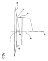
- Figure 2 shows a winding disk as a device for producing an advantageous bead core in a side view.
Die Figur 1 zeigt einen erfindungsgemäßen Wulstkern 2 im perspektivischen Halbschnitt. In gestrichelter Linie ist der Wulstbereich des Fahrzeugluftreifens 1 dargestellt, in den dieser Wulstkern 2 eingebaut werden soll. Der Wulstkern 2 besteht über dem größten Teil seines Umfanges aus fünf Lagen 3.1 bis 3.5; in dem kleinen Umfangsbereich, der auch als Überlappung bezeichnet wird, zwischen dem Spiralenanfang 5 und dem Spiralenende 6 weist der Kern unter Hinzuziehung der Endlage 3.6 sechs Lagen auf. Alle Lagen 3 bestehen aus fünf Drähten 4.FIG. 1 shows a
Wie insbesondere am gekappten Ende 6 der Lage 3.6 zu erkennen ist, weisen in diesem Ausführungsbeispiel alle Lagen 3 eine radiale Schichtung ihrer Festigkeitsträger 4 auf; in der axialen Richtung ist die Erstreckung jeder Lage lediglich gleich der Festigkeitsträger-Stärke plus Kautschukbeschichtung. Gegenüber der bekannten flachen Lagenausrichtung sind die Lagenquerschnitte nun also um 90o gedreht und stehen im wesentlichen - in diesem Ausführungsbei spiel sogar exakt - hochkant.As can be seen in particular at the
Da die Kautschukbeschichtung vorteilhafterweise sehr dünn ausgeführt wird - bei maßstäblicher Darstellung im Bereich der Strichstärke - ist sie in Fig. 1 der Übersichtlichkeit halber nicht dargestellt.Since the rubber coating is advantageously made very thin - with scale representation in the area of the line width - it is not shown in FIG. 1 for the sake of clarity.
Die Fig. 2 zeigt eine Wickelspule 7 zur Herstellung erfindungsgemäßer Wulstkerne. Das Kernwickeln beginnt mit Heftung des Lagenanfanges auf die Bordscheibe 10, wobei sich die radial innerste Stelle der ersten Lage in der Kehle 11 geen die Anschlagsfläche 9 abstützt. Die Bordscheibe 10 ist in diesem Ausführungsbeispiel um 80o gegenüber der Rotationsachse 8 geneigt. Die Neigung der Anschlagsfläche 9 gegenüber der senkrecht stehenden Rotat ionsachse 8 beträgt in diesem Ausführungsbeispiel α = 5o. Damit ergibt sich ein Kehlenwinkel γ von 105o.2 shows a
Die Erfindung ist nicht auf die dargestellten Ausführungsbei spiele beschränkt; beispielsweise lauten die Winkel für eine Kernwickelscheibe zur Herstellung eines Kernes wie in Fig. 1 dargestellt: α = 0o, β = 90o, γ = 90o. Das Wesentliche erfindungsgemäßer Wulstkerne ist lediglich, daß ihre radial innere Seite im wesentlichen durch die schmalen Stirnseiten hochkant stehender, aufgespulter Lagen gebildet ist, so daß die Störstellen Wickelanfang (und Wickelende) von der radial inneren (bzw. radial äußeren) Seite, wo sie beim Pierce-Kern liegt (liegen), auf beide axialen Seiten der Wulstkerne verlagert ist (sind). Zwar weist der Pierce-Kern nur eine Störstel le auf für die Rundlaufgenauigkeit der Karkasse, nämlich den Wickelanfang, erfindungsgemäße Wulstkerne hingegen zwei Störstellen, nämlich Wickelanfang und Wickelende, die beide die Karkasse berühren, jedoch ist der Einfluß dieser Störstellen um Größenordnungen geringer, woraus der überlegene Rundlauf von Fahrzeugluftreifen mit erfindungsgemäßen Wulstkernen resultiert. Erfindungsgemäße Wulstkerne können sowohl bei ein- als auch mehr lagigen Karkassen angewendet werden und eignen sich besonders für die heute vorherrschenden Radialkarkassen. Der weitere Reifenaufbau erfordert im übrigen keine Änderungen.The invention is not limited to the illustrated Ausführungsbei games; For example, the angles for a core winding disk for producing a core are as shown in FIG. 1: α = 0 o , β = 90 o , γ = 90 o . The essence of bead cores according to the invention is only that their radially inner side is essentially formed by the narrow end faces of upright, wound layers, so that the defects at the winding start (and winding end) from the radially inner (or radially outer) side, where they The Pierce core lies (is) on both axial sides of the bead cores. Although the Pierce core only has one fault point for the concentricity of the carcass, namely the start of the winding, bead cores according to the invention, however, two fault points, namely the start and end of the winding, both of which touch the carcass, but the influence of these fault points is orders of magnitude less, from which the superior concentricity of pneumatic vehicle tires with bead cores according to the invention results. Bead cores according to the invention can be used both with single-layer and multi-layer carcasses and are particularly suitable for the radial carcasses prevailing today. The further tire construction does not require any changes.
Claims (9)
Applications Claiming Priority (2)
| Application Number | Priority Date | Filing Date | Title |
|---|---|---|---|
| DE19893929975 DE3929975A1 (en) | 1989-09-08 | 1989-09-08 | BULB CORE FOR AIR TIRES |
| DE3929975 | 1989-09-09 |
Publications (2)
| Publication Number | Publication Date |
|---|---|
| EP0416638A2 true EP0416638A2 (en) | 1991-03-13 |
| EP0416638A3 EP0416638A3 (en) | 1991-07-31 |
Family
ID=6388974
Family Applications (1)
| Application Number | Title | Priority Date | Filing Date |
|---|---|---|---|
| EP19900117238 Withdrawn EP0416638A3 (en) | 1989-09-08 | 1990-09-07 | Bead core for pneumatic tyre |
Country Status (3)
| Country | Link |
|---|---|
| EP (1) | EP0416638A3 (en) |
| JP (1) | JPH03148313A (en) |
| DE (1) | DE3929975A1 (en) |
Cited By (4)
| Publication number | Priority date | Publication date | Assignee | Title |
|---|---|---|---|---|
| EP0628434A1 (en) * | 1993-06-07 | 1994-12-14 | Continental Aktiengesellschaft | Vehicle tyre |
| EP0642936A1 (en) * | 1993-09-14 | 1995-03-15 | BRIDGESTONE/FIRESTONE, Inc. | Pneumatic tire having opposite spiral oriented beads |
| GB2317150A (en) * | 1996-08-12 | 1998-03-18 | Bridgestone Corp | Tire bead core |
| EP0899132A1 (en) * | 1997-08-27 | 1999-03-03 | Bridgestone Corporation | Pneumatic tyres |
Citations (3)
| Publication number | Priority date | Publication date | Assignee | Title |
|---|---|---|---|---|
| US1503985A (en) * | 1923-03-19 | 1924-08-05 | William G Corson | Grommet |
| GB2043558A (en) * | 1979-02-19 | 1980-10-08 | Michelin & Cie | Bead wires for the beads of tubeless pneumatic tyres |
| DE3613350A1 (en) * | 1986-04-19 | 1987-10-22 | Continental Gummi Werke Ag | Core ring for the beads of pneumatic tyres |
Family Cites Families (4)
| Publication number | Priority date | Publication date | Assignee | Title |
|---|---|---|---|---|
| DE2409816A1 (en) * | 1974-03-01 | 1975-09-11 | Continental Gummi Werke Ag | Bead cores for automobile tyres - consist of annular discs contg. spirally wound, axially combined bonded wire coils |
| DE3613349A1 (en) * | 1986-04-19 | 1987-10-22 | Continental Gummi Werke Ag | Core ring for the beads of pneumatic tyres |
| US4820563A (en) * | 1987-08-13 | 1989-04-11 | National-Standard Company | Tire bead assembly |
| DE3738446A1 (en) * | 1987-11-12 | 1989-05-24 | Uniroyal Englebert Gmbh | VEHICLE TIRES |
-
1989
- 1989-09-08 DE DE19893929975 patent/DE3929975A1/en not_active Withdrawn
-
1990
- 1990-09-07 JP JP2235988A patent/JPH03148313A/en active Pending
- 1990-09-07 EP EP19900117238 patent/EP0416638A3/en not_active Withdrawn
Patent Citations (3)
| Publication number | Priority date | Publication date | Assignee | Title |
|---|---|---|---|---|
| US1503985A (en) * | 1923-03-19 | 1924-08-05 | William G Corson | Grommet |
| GB2043558A (en) * | 1979-02-19 | 1980-10-08 | Michelin & Cie | Bead wires for the beads of tubeless pneumatic tyres |
| DE3613350A1 (en) * | 1986-04-19 | 1987-10-22 | Continental Gummi Werke Ag | Core ring for the beads of pneumatic tyres |
Cited By (6)
| Publication number | Priority date | Publication date | Assignee | Title |
|---|---|---|---|---|
| EP0628434A1 (en) * | 1993-06-07 | 1994-12-14 | Continental Aktiengesellschaft | Vehicle tyre |
| EP0642936A1 (en) * | 1993-09-14 | 1995-03-15 | BRIDGESTONE/FIRESTONE, Inc. | Pneumatic tire having opposite spiral oriented beads |
| GB2317150A (en) * | 1996-08-12 | 1998-03-18 | Bridgestone Corp | Tire bead core |
| US5871603A (en) * | 1996-08-12 | 1999-02-16 | Bridgestone Corporation | Pneumatic tires with organic or inorganic fiber cord bead core |
| GB2317150B (en) * | 1996-08-12 | 2000-08-30 | Bridgestone Corp | Pneumatic tires |
| EP0899132A1 (en) * | 1997-08-27 | 1999-03-03 | Bridgestone Corporation | Pneumatic tyres |
Also Published As
| Publication number | Publication date |
|---|---|
| DE3929975A1 (en) | 1991-03-21 |
| JPH03148313A (en) | 1991-06-25 |
| EP0416638A3 (en) | 1991-07-31 |
Similar Documents
| Publication | Publication Date | Title |
|---|---|---|
| DE856517C (en) | Process for the production of pneumatic vehicle tires using the flat belt process | |
| DE1283691B (en) | Pneumatic vehicle tires | |
| DE1505112B1 (en) | Method for producing a pneumatic vehicle tire | |
| DE69830826T2 (en) | Improved pneumatic tire construction and manufacturing process | |
| EP0622251B1 (en) | Non-pneumatic tyre | |
| DE2204746A1 (en) | TUBELESS VEHICLE TIRE | |
| DE1811770B2 (en) | Vulcanizable, substantially cylindrical blank for making a pneumatic tire | |
| DE1815714A1 (en) | Inflatable, unvulcanized vehicle tires made of elastomer material with reinforcement threads | |
| AT394003B (en) | TIRE | |
| DE112014005712T5 (en) | Pneumatic tire and method of making same | |
| EP0537780A2 (en) | Method of making a wrapped layer for a tyre | |
| EP0628434B1 (en) | Vehicle tyre | |
| EP1888325B1 (en) | Method for producing a pneumatic tyre for a vehicle | |
| DE4208705A1 (en) | MANUFACTURING PROCESS FOR A GOOD | |
| EP0416638A2 (en) | Bead core for pneumatic tyre | |
| EP0052737B1 (en) | Pneumatic tyre | |
| DE3227138C2 (en) | ||
| DE2603349A1 (en) | TIRE | |
| DE2439092A1 (en) | TIRE | |
| EP1718480B1 (en) | Pneumatic tire for vehicle | |
| DE2505741C3 (en) | Bead core for pneumatic vehicle tires | |
| DE1034495B (en) | Ring-shaped pneumatic tire insert that is resistant to tensile loads | |
| DE4203568A1 (en) | Pneumatic tyre with continuous spirally-wound carcass cord layer - has touching turns to improve tyre stiffness and avoid delamination due to edges formed by cord ends | |
| DE3738446A1 (en) | VEHICLE TIRES | |
| DE1043843B (en) | Annular insert for pneumatic tires for vehicle wheels |
Legal Events
| Date | Code | Title | Description |
|---|---|---|---|
| PUAI | Public reference made under article 153(3) epc to a published international application that has entered the european phase |
Free format text: ORIGINAL CODE: 0009012 |
|
| AK | Designated contracting states |
Kind code of ref document: A2 Designated state(s): DE ES FR GB IT |
|
| PUAL | Search report despatched |
Free format text: ORIGINAL CODE: 0009013 |
|
| AK | Designated contracting states |
Kind code of ref document: A3 Designated state(s): DE ES FR GB IT |
|
| 17P | Request for examination filed |
Effective date: 19910624 |
|
| 17Q | First examination report despatched |
Effective date: 19930726 |
|
| RAP1 | Party data changed (applicant data changed or rights of an application transferred) |
Owner name: CONTINENTAL AKTIENGESELLSCHAFT |
|
| STAA | Information on the status of an ep patent application or granted ep patent |
Free format text: STATUS: THE APPLICATION IS DEEMED TO BE WITHDRAWN |
|
| 18D | Application deemed to be withdrawn |
Effective date: 19940317 |