EP0415355A2 - Moyens de verrouillage pour une serrure, notamment pour une serrure à câble - Google Patents
Moyens de verrouillage pour une serrure, notamment pour une serrure à câble Download PDFInfo
- Publication number
- EP0415355A2 EP0415355A2 EP19900116492 EP90116492A EP0415355A2 EP 0415355 A2 EP0415355 A2 EP 0415355A2 EP 19900116492 EP19900116492 EP 19900116492 EP 90116492 A EP90116492 A EP 90116492A EP 0415355 A2 EP0415355 A2 EP 0415355A2
- Authority
- EP
- European Patent Office
- Prior art keywords
- locking
- plug part
- locking device
- guide element
- body guide
- Prior art date
- Legal status (The legal status is an assumption and is not a legal conclusion. Google has not performed a legal analysis and makes no representation as to the accuracy of the status listed.)
- Granted
Links
- 230000007246 mechanism Effects 0.000 claims abstract description 39
- 238000003780 insertion Methods 0.000 claims description 19
- 230000037431 insertion Effects 0.000 claims description 19
- 239000004033 plastic Substances 0.000 claims description 11
- 229920001971 elastomer Polymers 0.000 claims description 9
- 230000007704 transition Effects 0.000 claims description 9
- 238000006073 displacement reaction Methods 0.000 claims description 5
- 229920002379 silicone rubber Polymers 0.000 claims description 5
- 239000004945 silicone rubber Substances 0.000 claims description 5
- 230000002401 inhibitory effect Effects 0.000 claims description 4
- 238000007789 sealing Methods 0.000 claims description 4
- 238000013475 authorization Methods 0.000 claims 1
- 230000000903 blocking effect Effects 0.000 abstract 1
- 230000007257 malfunction Effects 0.000 description 4
- 230000009471 action Effects 0.000 description 3
- 239000000463 material Substances 0.000 description 3
- 239000003112 inhibitor Substances 0.000 description 2
- 230000004048 modification Effects 0.000 description 2
- 238000012986 modification Methods 0.000 description 2
- 230000036316 preload Effects 0.000 description 2
- 230000004323 axial length Effects 0.000 description 1
- 230000008901 benefit Effects 0.000 description 1
- 238000011109 contamination Methods 0.000 description 1
- 230000007797 corrosion Effects 0.000 description 1
- 238000005260 corrosion Methods 0.000 description 1
- 238000013016 damping Methods 0.000 description 1
- 230000002349 favourable effect Effects 0.000 description 1
- 239000012530 fluid Substances 0.000 description 1
- 238000007654 immersion Methods 0.000 description 1
- 239000002184 metal Substances 0.000 description 1
- 230000000149 penetrating effect Effects 0.000 description 1
- 230000000717 retained effect Effects 0.000 description 1
- 239000007787 solid Substances 0.000 description 1
Images


Classifications
-
- E—FIXED CONSTRUCTIONS
- E05—LOCKS; KEYS; WINDOW OR DOOR FITTINGS; SAFES
- E05B—LOCKS; ACCESSORIES THEREFOR; HANDCUFFS
- E05B67/00—Padlocks; Details thereof
- E05B67/003—Chain, wire or cable locks
-
- E—FIXED CONSTRUCTIONS
- E05—LOCKS; KEYS; WINDOW OR DOOR FITTINGS; SAFES
- E05B—LOCKS; ACCESSORIES THEREFOR; HANDCUFFS
- E05B67/00—Padlocks; Details thereof
- E05B67/36—Padlocks with closing means other than shackles ; Removable locks, the lock body itself being the locking element; Padlocks consisting of two separable halves or cooperating with a stud
- E05B67/365—Padlocks with closing means other than shackles ; Removable locks, the lock body itself being the locking element; Padlocks consisting of two separable halves or cooperating with a stud with locking means in the form of balls or rollers
-
- Y—GENERAL TAGGING OF NEW TECHNOLOGICAL DEVELOPMENTS; GENERAL TAGGING OF CROSS-SECTIONAL TECHNOLOGIES SPANNING OVER SEVERAL SECTIONS OF THE IPC; TECHNICAL SUBJECTS COVERED BY FORMER USPC CROSS-REFERENCE ART COLLECTIONS [XRACs] AND DIGESTS
- Y10—TECHNICAL SUBJECTS COVERED BY FORMER USPC
- Y10T—TECHNICAL SUBJECTS COVERED BY FORMER US CLASSIFICATION
- Y10T70/00—Locks
- Y10T70/40—Portable
- Y10T70/413—Padlocks
- Y10T70/437—Key-controlled
- Y10T70/483—Flexible shackle
-
- Y—GENERAL TAGGING OF NEW TECHNOLOGICAL DEVELOPMENTS; GENERAL TAGGING OF CROSS-SECTIONAL TECHNOLOGIES SPANNING OVER SEVERAL SECTIONS OF THE IPC; TECHNICAL SUBJECTS COVERED BY FORMER USPC CROSS-REFERENCE ART COLLECTIONS [XRACs] AND DIGESTS
- Y10—TECHNICAL SUBJECTS COVERED BY FORMER USPC
- Y10T—TECHNICAL SUBJECTS COVERED BY FORMER US CLASSIFICATION
- Y10T70/00—Locks
- Y10T70/40—Portable
- Y10T70/413—Padlocks
- Y10T70/487—Parts, accessories, attachments and adjuncts
- Y10T70/493—Protectors
-
- Y—GENERAL TAGGING OF NEW TECHNOLOGICAL DEVELOPMENTS; GENERAL TAGGING OF CROSS-SECTIONAL TECHNOLOGIES SPANNING OVER SEVERAL SECTIONS OF THE IPC; TECHNICAL SUBJECTS COVERED BY FORMER USPC CROSS-REFERENCE ART COLLECTIONS [XRACs] AND DIGESTS
- Y10—TECHNICAL SUBJECTS COVERED BY FORMER USPC
- Y10T—TECHNICAL SUBJECTS COVERED BY FORMER US CLASSIFICATION
- Y10T70/00—Locks
- Y10T70/70—Operating mechanism
- Y10T70/7441—Key
- Y10T70/7751—With ball or roller
Definitions
- the invention relates to a locking device for a lock, in particular a ring lock, comprising a plug part and a plug part receptacle with a latching device which can be actuated by a locking mechanism, which allows the plug part to be inserted in a basic position of the locking mechanism, but which blocks the withdrawal of the plug part, and which in a release position the locking mechanism allows the plug part to be withdrawn, a catch shoulder being attached to the plug part and the catch device having at least one catch body movable and lockable transversely to the direction of insertion of the plug part for engagement behind the catch shoulder.
- such a locking device for a cable lock for bicycles.
- one end of the cable is firmly connected to the connector part receptacle.
- the plug part receptacle comprises the locking mechanism arranged in a housing and biased into the basic position.
- An insertion channel for the plug part is also provided in the housing.
- the latching body has an L-shaped shape, the longer section of the L partially protruding into the insertion channel through a recess.
- the other end of the cable is also firmly connected to the plug part.
- the plug part is inserted into the insertion channel, displacing the L-shaped locking body from the insertion channel until the locking shoulder has passed the locking body.
- the pre-tensioned locking body can swivel back into the insertion channel. If an attempt is now made to pull the plug part out against the insertion movement, the locking shoulder comes into contact with the locking body. This will prevents a further pull-out movement of the plug part. If the lock is to be opened, the locking body is pivoted out of the insertion channel by a rotary movement of the locking mechanism and thereby releases the plug part. This can now be pulled out. In this locking device it proves disadvantageous that the locking body is supported after locking on an edge of the recess in the insertion channel. If, when the lock is locked, an attempt is made to pull the plug part out of the insertion channel with high force, the locking body can shear off at this edge. So that such a lock fulfills its function as an anti-theft device, both the locking body and the housing must be heavy and solid. In addition, the locking body is insufficiently guided in the housing, whereby a malfunction of the locking device is not excluded.
- the invention has for its object to provide a locking device of the type mentioned in such a way that the disadvantages of the prior art are eliminated.
- the latching body is received in a guide passage of a latching body guide element directed transversely to the direction of insertion of the plug part and is opposite a control surface on its side remote from the inserted plug part, the control surface of the latching body in a pull-out movement of the latching body in a locked position of the latching body guide element Plug part locking engagement urges behind the locking shoulder, wherein the locking body guide element can be moved by the retraction body through the retracting connector part in a first alternative position, in which the locking body through the control surface for a Evasion movement is released, and wherein the locking body guide element can be rotated by turning the locking mechanism in a second evasion position, in which the locking body is released by the control surface for an evasive movement allowing the plug part to be pulled out.
- a particular advantage of the solution according to the invention is that it opens up a wealth of possibilities for the structural design.
- the proposed solution also creates the precondition for the fact that, according to a configuration to be dealt with later, several latching bodies can be used at the same time without the possibility of inserting the plug part leading to latching being lost in the basic position of the locking mechanism.
- the locking body guide element automatically arrives in the locking position after insertion of the plug part, it is proposed that the locking body guide element is prestressed in the locking position.
- the locking body guide element is biased in the axial direction and in the circumferential direction at the same time by a helical spring, this ensures that the locking body guide element not only automatically enters the locking or locking position after inserting the plug part, but also automatically after opening the lock, by means of a single biasing element is returned to a standby position for locking.
- the locking device has a simple structure and small external dimensions, with optimal protection against contamination.
- the locking body guide element is axially movably guided on a rotating part of the locking mechanism and is in rotary driving engagement with this rotating part.
- the locking body guide element is axially displaceably and rotatably guided by parts of the control surface, malfunctions due to poor or nonexistent guidance of the locking body guide element are avoided.
- one or more, in particular two, locking bodies can be provided.
- locking bodies it is expedient if these are distributed approximately uniformly over the circumference of the plug part. This results in a particularly favorable, ring-shaped load when trying to pull out the plug part without actuating the locking mechanism.
- the latching bodies can have different geometric shapes. For example, barrel-shaped rolls can be used. It when the latching body or bodies are formed by a ball is particularly advantageous.
- the locking body guide element can have different geometric shapes. It when the latching body guide element is bell-shaped is particularly advantageous, wherein it is in the bell crest in rotary driving connection with the rotating part and is movable relative to this rotating part in its axial direction. This training is optimally tailored to the function of the element.
- the locking device according to the invention can be used for a wide variety of purposes. If the plug part and the plug part receptacle are each connected to one end of a cable of a ring lock, it can be used, for example, as a bicycle lock. On the other hand, there is the possibility that a chain or a long bracket will replace the cable. However, any other connection between the plug part and the plug part receptacle is also conceivable. If the cable end assigned to the plug part receptacle is anchored in an inner housing, which, if necessary, surrounds the locking mechanism with an armor function within an outer housing of the plug part receptacle, this represents an additional anti-theft device.
- the locking body is biased by biasing means in the direction of engagement with the plug part.
- this measure makes unauthorized attempts to open difficult by accelerating the plug part receptacle and pulling force on the plug part.
- the prestressing can be done in the simplest way by means of an elastic ring, for example an O-ring. So that the locking and opening of the lock can be carried out in a single fluid movement, it is proposed that the various control surface regions of the control surface interacting with the latching body connect to one another via curves. Additionally or alone, it can also be provided that at the insertion end of the plug part is arranged a locking body displacement slope.
- the locking mechanism returns to its basic position after actuation, it is advantageous if it is resiliently biased into it.
- Any known shape can be used as the locking mechanism. It is particularly expedient if it is a key-operated locking mechanism, in particular a cylinder lock.
- the latching shoulder can strike against the latching body when the locking device is exposed to vibrations, such as can occur when the locking device is used in a cable lock for bicycles and this lock is carried on the bike while driving.
- vibrations such as can occur when the locking device is used in a cable lock for bicycles and this lock is carried on the bike while driving.
- the latching body and / or the latching shoulder can be damaged over time, which means that the locking device can malfunction.
- a spring element is provided between the plug part and the plug part receptacle, which in the locked position urges the locking shoulder into abutment against the locking body.
- the spring element can be ring-shaped and made of silicone rubber, silicone rubber being a particularly easy-to-shape and inexpensive material.
- the spring element is designed as a sealing element for sealing between the plug part and the plug part receptacle when the plug part is inserted.
- the housing of the connector part receptacle is made of metal, it can easily corrode.
- the connector part receptacle be enclosed by a rubber or plastic jacket.
- the rubber or plastic jacket can represent an additional anti-theft device, since this is a particularly tough material that is difficult to cut.
- the rubber or plastic jacket can, for example, be shrunk onto the connector part receptacle.
- a particularly simple assembly of the jacket is achieved if the rubber or plastic jacket is composed of at least two parts which are connected to one another, preferably locked in place.
- the locking device is used in a bicycle lock in which the plug part receptacle and the plug part are connected via a ring cable, which is preferably made of wire cable, it may be necessary to protect the cable against corrosion.
- a ring cable which is preferably made of wire cable
- the rubber or plastic jacket connects to a hose which surrounds a ring cable. If the hose is made of a tough material, it also represents another anti-theft device.
- an inhibiting device is provided between the rotating part and the locking body guide element, which inhibits the axial movement of the locking body guide element compared to the rotating part when the plug part is inserted manually into the plug part receptacle, but inhibits an abrupt axial movement of the locking body guide element with respect to the turned part, for example by accelerating the plug part receptacle.
- the inhibitor can be constructed in very different ways.
- the guide between the locking body guide element and the rotating part is designed with swirl distribution means such that an axial movement of the locking body guide element relative to the rotating part inevitably overlaps a relative movement of the two parts.
- the rotary part engages in the locking position with a portion of a smaller cross section in a rotary driving opening of the locking body guide element, allowing a rotational angle play canceled by torsional preload, and that the rotating part engages in the first alternative position with a portion of larger cross section in the rotary driving opening, with the Transition from the section of smaller cross-section to the section of larger cross-section roof-shaped transition surfaces are arranged, which force a relative rotation of the rotating part and locking body guide element when the section of larger cross-section enters the rotary driving opening.
- the inhibiting device is formed by a suitable damping device.
- a locking device for a cable ring lock is shown, the two ends of a locking cable with 10 and 12 are designated.
- One end 10 of the locking cable is connected to a plug part 14, the other end 12 of the locking cable is connected to a plug part receptacle, generally designated 16.
- the plug part 14 has a constriction 18 with a locking shoulder 20.
- This locking shoulder 20 engages in Fig. 1 locking body forming locking balls 22 which in one bell-shaped locking body guide element 24 are received, specifically in guide passages 26 of the locking body guide element 24.
- the locking body guide element 24 is accommodated within a housing 28 of the plug part receptacle 16. 1 and 2 (locking position of the locking body guide element 24), the locking balls 22 are immovable radially outwards in that they rest on control surface regions 31 of a control surface 30 on an inside of the housing 28.
- the locking body guide element 24 is secured in the state shown in FIG. 1 against rotation about the axis XX by a key-operated locking mechanism 32, namely by a locking cylinder core 32a with an integrally formed rotating part 34 which is rotatably mounted in the locking mechanism 32 when the key is pulled (not shown) with respect to the locking mechanism 32 non-rotatably assumes the rotational position shown in FIGS. 1 and 2 and can be rotated clockwise after inserting the key by means of the key from the position shown in FIGS. 1 and 2.
- the locking body guide element 24 has a rotary driving opening 24a, in which the rotating part 34 engages.
- the locking body guide element 24 sits on this rotating part 34 of the locking cylinder core 32a.
- the locking cylinder core 32a is rotated together with the rotating part 34 and thus also the locking body guide element 24 in the clockwise direction, ie in the direction of arrow 38 in FIG. 2, so that the locking balls 22 reach control surface areas 40 of the control surface 30 and radially can dodge outwards with respect to the axis XX (second dodge position of the locking body guide element 24).
- the control surface areas 40 of the control surface 30 are formed in that the control surface 30 in its lower Area, as indicated at 42, has a diamond-shaped cross section.
- the locking balls 22 face the control surface regions 40, they can deflect radially outwards when the plug part 14 is removed, so that the plug part 14 can be removed from the plug part receptacle 16.
- the radial outward displacement of the locking balls 22 is possible by appropriate profiling of the constriction 18, and in particular in that the locking shoulder 20 rests radially inward of the center of the ball of the locking balls 22.
- the locking body guide element 24 is pressed down against a lower stop surface 46 of the housing 28 by a helical spring 44 fixed to it. At the same time, the locking body guide element 24 is subject to a torsional prestress by the helical spring 44, which tries to turn the locking body guide element 24 into a position in which the locking balls 22 bear against the control surface regions 31. To fix the helical spring 44, a wire end of the spring 44 is inserted into a receiving bore 24b of the locking body guide element (cf. FIGS. 4 and 7).
- the locking body guide element 24 After uncoupling the plug part 14 and releasing the key, the locking body guide element 24, under the action of the helical spring 44, returns to the position in which the locking balls 22 rest against the control surface regions 31 (ready position for locking). Despite the disengagement of the plug part 14, the locking balls 22 cannot fall radially inward out of the guide passages 26 because the guide passages 26 are constricted at their radially inner ends, as a result of which the locking balls 22 are retained.
- a key actuation is not required to re-engage the plug part 14 into the plug part receptacle 16.
- the plug part 14 is, based on the illustration of the locking device in FIG. 1, inserted from below into the bell-shaped locking body guide element 24 and thereby abuts the locking balls 22. Since the locking balls 22 abut the control surface regions 31, they cannot initially move radially outwards dodge. However, the locking body guide element 24 can be moved upwards by the plug part 14 pressed in by means of the locking balls 22 against the action of the helical spring 44, the locking body guide element 24 being moved upwards on the locking cylinder core 32a (first alternative position of the locking body guide element 24, cf. Fig. 7).
- the locking balls 22 reach control surface areas 48 of the control surface 30.
- the housing 28 is widened at the cross-section II-II compared to the diamond-shaped cross-section 42 of the lower region.
- the locking balls 22 reach the control surface areas 48, they are displaced radially outwards by a locking body displacement bevel 50 at the upper end of the plug part 14 until the locking shoulder 20 has passed over the locking balls 22 and the locking balls 22 again into the constriction 18 can occur.
- the locking body guide element 24 moves downward again under the pressure of the coil spring 44.
- the locking balls 22 return to the control surface areas 31 and are thereby pressed radially inward again into the constriction 18 of the connector part 14, so that the state according to FIGS. 1 and 2 is restored.
- the radial inward movement of the locking balls 22 can be supported by the fact that on the radially outer part of the locking balls 22nd there is an elastic O-ring 52 which tries to urge the two locking balls 22 radially inwards.
- the locking mechanism 32 is housed within the housing 28, specifically in an armored inner housing 54, which is fixed in its installed position by warts 56 of the housing 28 and corresponding recesses 58 at the lower edge of the inner housing 54.
- the inner housing 54 is secured by a cover disk 60, which is held in place by a flange 62 of the housing 28.
- the coil spring 44 is supported in a recess 64 of the inner housing 54.
- the cover plate 60 and the flange 62 are annular, so that they allow access 66 for the key.
- the locking mechanism 32 can be a conventional locking cylinder, the locking cylinder core of which has already been mentioned at 32a.
- the rotational path of the lock cylinder core 32a is defined within the locking mechanism 32 such that the locking balls 22 abut the control surface regions 31 at one end of this rotational path and the locking balls 22 face the control surface regions 40 at the other end of the rotational path.
- the helical spring 44 gives the locking cylinder core 32a a pretension in the direction of that end position in which the detent balls 22 face or rest against the control surface regions 31.
- the ring cable end 12 is anchored with a cable block 68 in the inner housing 54, specifically by means of a U-leaf 70, which is inserted into a slot 72 of the inner housing 54 before the cover disk 60 is applied and enters an annular groove 74 of the cable block 68.
- a U-leaf 70 By flattening the cable block 68 and corresponding counter-flattening of the inner housing 54, the cable block 68 is secured against rotation relative to the inner housing 54.
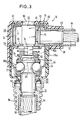
- Fig. 3 it is shown that the housing 28 is covered by a plastic sheath 76.
- the plastic sheath 76 consists of two sheath parts 78 and 80 which are plugged together and locked against one another.
- the sheath part 80 comprises a cable bushing 82 which comprises a cable sheath 84 surrounding the cable 12.
- the jacket part 80 is chamfered at its lower end 80a in such a way that it can be pressed over the flange 62 while pushing the cable bushing 82 towards the housing 28 and then snaps into the position according to FIG. 3, in which it snaps with the jacket part 78 can be locked.
- a rib 78a of the jacket part 78 engages in a recess 80b of the jacket part 80, so that the jacket part 78 is fixed non-rotatably.
- the cable sheath 84 is enclosed by a closing piece 86, which also includes the plug part 14.
- a silicone rubber sleeve 88 is fixed to the connector part 14 by the end piece 86 and rests with an end face 90 under elastic prestress against a contact surface 92 of the jacket part 78, so that a seal is formed here, which prevents dirt and moisture from penetrating prevented in the interior of the connector receptacle 16.
- the axially elastic silicone rubber sleeve 88 has another function: it generates a bias on the plug part 14 axially downward, through which the locking shoulder 20 is pressed against the locking balls 22, so that the plug part 14 and the locking balls 22 in the locked position are held wobble-free.
- the locking body guide element 24 on the housing 28 is guided axially displaceably and rotatably by guide surfaces 30a of the control surface 30 in the lower region of the control surface 30.
- These Guide surfaces 30a are formed by curves of the diamond-shaped lower housing part 42.
- FIG. 4-8 shows a further embodiment of the locking device according to the invention, the same components being provided with the same reference numerals.
- the locking device shown there differs from the locking devices shown in FIGS. 1-3 in that it has a modified rotating part 34 '.
- This rotary part 34 ' is provided with a section 35a remote from the locking mechanism, which engages in the rotary driving opening 24a of the locking body guide element 24.
- There is an angle of rotation play between the rotary driving opening 24a and this section 35a with a smaller cross-section see FIG. 5
- the rotational preload applied by the coil spring 44 so that a positive rotary driving connection between the section 35a with a smaller cross-section and the locking body guide element 24 consists.
- the rotating part 34 ' also has a section 35b near the locking mechanism of larger cross section, which engages in the rotary driving opening 24a when the locking body guide element 24 is in its first evasive position (cf. FIG. 7).
- the section 35a with a smaller cross section and the section 35b with a larger cross section are each formed by two flats of the cylindrical rotating part 34 ′ arranged parallel to one another, the section 35a being circumferentially at an angle, in particular an angle between 2 ° and 10 °, relative to the section 35b. preferably 6 °, is rotated (see. Fig. 6a, 6b).
- the transition from the section 35a with a smaller cross section to the section 35b with a larger cross section is formed by roof-shaped transition surfaces 35c which have an angle with respect to the axis of the rotating part 34 ', in particular an angle between 40 ° and 60 °, preferably 50 °.
- the axial length of the two arranged parallel to each other Areas of the section 35a of smaller cross-section essentially correspond to the immersion depth of this section 35a in the rotary driving opening 24a in the basic position of the locking device.
- the transition surfaces 35c force a relative rotation of the locking body guide element 24 with respect to the rotating part 34 'against the bias of the coil spring 44 when the section 35b of larger cross-section enters the rotary driving opening 24a (see FIGS. 7 and 8).
- the section 35a with a smaller cross section, the section 35b with a larger cross section and the transition surfaces 35c together form an inhibiting device.
- This inhibitor can be easily overcome during the operational insertion of the connector part 14 into the connector part receptacle 16, with a slight rotation of the locking body guide element 24 relative to the rotating part 34 'by an angle of 2 ° - 10 °, preferably about 6 °.
- the transition surfaces 35c prevent the locking body guide element 24 from sliding onto the section 35b of larger cross section when the connector part 14 and the connector part receptacle 16 are accelerated relative to one another, and the locking body guide element 24 thus comes into an evasive position in which the locking balls 22 can deflect radially outward. This prevents an inadvertent opening of the locking device in the event of sudden mass forces, which further increases the functional reliability of the locking device.
Landscapes
- Details Of Connecting Devices For Male And Female Coupling (AREA)
- Lock And Its Accessories (AREA)
- Quick-Acting Or Multi-Walled Pipe Joints (AREA)
Applications Claiming Priority (4)
| Application Number | Priority Date | Filing Date | Title |
|---|---|---|---|
| DE3928545 | 1989-08-29 | ||
| DE3928545 | 1989-08-29 | ||
| DE4017122 | 1990-05-28 | ||
| DE19904017122 DE4017122A1 (de) | 1989-08-29 | 1990-05-28 | Schliessvorrichtung fuer ein schloss, insbesondere ringschloss |
Publications (3)
| Publication Number | Publication Date |
|---|---|
| EP0415355A2 true EP0415355A2 (fr) | 1991-03-06 |
| EP0415355A3 EP0415355A3 (en) | 1991-11-21 |
| EP0415355B1 EP0415355B1 (fr) | 1996-04-10 |
Family
ID=25884531
Family Applications (1)
| Application Number | Title | Priority Date | Filing Date |
|---|---|---|---|
| EP19900116492 Expired - Lifetime EP0415355B1 (fr) | 1989-08-29 | 1990-08-28 | Moyens de verrouillage pour une serrure, notamment pour une serrure à câble |
Country Status (4)
| Country | Link |
|---|---|
| US (1) | US5170650A (fr) |
| EP (1) | EP0415355B1 (fr) |
| DE (2) | DE4017122A1 (fr) |
| ES (1) | ES2088397T3 (fr) |
Cited By (9)
| Publication number | Priority date | Publication date | Assignee | Title |
|---|---|---|---|---|
| EP0520154A1 (fr) * | 1991-06-24 | 1992-12-30 | Aug. Winkhaus GmbH & Co. KG | Dispositif de fixation d'un câble sur un cadre de bicyclette |
| EP0621385A2 (fr) * | 1993-03-16 | 1994-10-26 | Security Tag Systems, Inc. | Dispositif de serrage enlevé par aimants |
| DE4434585A1 (de) * | 1994-09-28 | 1996-04-04 | Bremicker Soehne Kg A | Schloß |
| US6055832A (en) * | 1997-09-16 | 2000-05-02 | Wyers; Philip W. | Locking device |
| US6672115B2 (en) | 2000-04-24 | 2004-01-06 | Philip W. Wyers | Locking device with convertible shank |
| US6862905B2 (en) | 2001-02-12 | 2005-03-08 | Master Lock Company | Pin locking device and method of locking |
| EP2295683A1 (fr) * | 2009-08-27 | 2011-03-16 | ABUS August Bremicker Söhne KG | Verrou à boucle doté d'un axe de cylindre décalé |
| EP2585658A4 (fr) * | 2010-06-23 | 2017-09-27 | Fire & Security Hardware Pty Ltd | Mécanisme de verrouillage |
| CN108005487A (zh) * | 2017-11-28 | 2018-05-08 | 宁波美固力磁电有限公司 | 一种快速插接锁结构 |
Families Citing this family (21)
| Publication number | Priority date | Publication date | Assignee | Title |
|---|---|---|---|---|
| US5467619A (en) * | 1989-03-22 | 1995-11-21 | Star Lock Systems, Inc. | Post latching systems |
| US5447043A (en) * | 1994-02-24 | 1995-09-05 | Hwang; Meei-Lih | Lock assembly with flexible shackle |
| DE4412056C2 (de) * | 1994-04-07 | 1996-12-19 | Easec Schloss Production Gmbh | Kabelschloß |
| US5568740A (en) * | 1995-08-15 | 1996-10-29 | Lin; Yung-Ta | Steel wire rope lock |
| DE19601343A1 (de) | 1996-01-16 | 1997-07-17 | Winkhaus Fa August | Schloßvorrichtung, insbesondere für Zweiradfahrzeuge |
| US5761934A (en) * | 1996-10-22 | 1998-06-09 | Kuo; Li-Tsao | Cable lock and an universal hold-down support |
| US5829280A (en) * | 1997-10-16 | 1998-11-03 | Chong-Kuan Ling | Cable locking device with automatic pop-up feature |
| US5992187A (en) * | 1998-06-15 | 1999-11-30 | Derman; Jay S. | Lockable shaft retainer |
| US6854302B2 (en) * | 2001-07-10 | 2005-02-15 | Master Lock Company | Pneumatic tool lock |
| US6477870B1 (en) * | 2002-01-04 | 2002-11-12 | Jay S. Derman | Cable end tubular lock |
| DE102006019285A1 (de) * | 2006-04-26 | 2007-10-31 | Bayerische Motoren Werke Ag | Stiftschloss für eine Scheibe, Tür oder Klappe |
| US8842422B2 (en) | 2006-10-23 | 2014-09-23 | ACCO Brands Corporation | Security apparatus |
| NZ565163A (en) * | 2007-01-18 | 2008-09-26 | Assa Abloy Australia Pty Ltd | A padlock suitable for use in hazardous environments |
| US20110036129A1 (en) * | 2009-08-12 | 2011-02-17 | Frantz Donald R | Receiver lock assembly |
| ES2729987T3 (es) * | 2014-08-27 | 2019-11-07 | Invue Security Products Inc | Sistemas y métodos para bloquear un sensor a una base |
| DE102016104474A1 (de) * | 2016-03-11 | 2017-09-14 | ABUS August Bremicker Söhne KG | Kettenschloss |
| CN207185596U (zh) * | 2017-02-28 | 2018-04-06 | 深圳市酷伴科技有限公司 | 宠物玩耍球自动发射器 |
| EP3589806B1 (fr) * | 2017-03-01 | 2022-04-13 | Carrier Corporation | Module de verrouillage et procédé de fonctionnement d'un module de verrouillage |
| US12018516B2 (en) | 2021-06-30 | 2024-06-25 | Delta Cycle Corporation | Electronic lock |
| US12024924B2 (en) | 2021-07-01 | 2024-07-02 | Delta Cycle Corporation | Electronic lock |
| US12060733B2 (en) * | 2021-08-16 | 2024-08-13 | Delta Cycle Corporation | Bicycle cable lock |
Citations (1)
| Publication number | Priority date | Publication date | Assignee | Title |
|---|---|---|---|---|
| GB1567322A (en) * | 1977-01-19 | 1980-05-14 | Weeks & Taylor | Locking assembly with deadlocking means |
Family Cites Families (31)
| Publication number | Priority date | Publication date | Assignee | Title |
|---|---|---|---|---|
| US1350392A (en) * | 1920-03-12 | 1920-08-24 | James M Taylor | Lock |
| US1419469A (en) * | 1921-01-03 | 1922-06-13 | Automatic Truck Brake Company | Automatic safety lock device |
| US1722525A (en) * | 1925-12-17 | 1929-07-30 | Junkunc John | Padlock |
| US1692826A (en) * | 1927-06-15 | 1928-11-27 | Ganz William | Lock |
| FR876347A (fr) * | 1941-10-27 | 1942-11-03 | Perfectionnement aux serrures anti-vol | |
| DE962322C (de) * | 1952-10-03 | 1957-04-18 | Raukamp & Co | Drahtseilschloss |
| US3187525A (en) * | 1962-06-07 | 1965-06-08 | Herbert F Dics | Padlock constructed for quick key change |
| US3143872A (en) * | 1962-06-28 | 1964-08-11 | Yale & Towne Inc | Padlock |
| US3221526A (en) * | 1962-07-23 | 1965-12-07 | Wells F Stackhouse | Meter padlock |
| US3186196A (en) * | 1963-08-07 | 1965-06-01 | Brooks Co E J | Plunger-type lock |
| DE1678062A1 (de) * | 1966-08-11 | 1971-08-12 | Waertsilae Oy Ab | Schloss |
| US3435642A (en) * | 1966-09-12 | 1969-04-01 | Andrew Del Pesco | Flexible shackle lock |
| FI42408B (fr) * | 1967-06-15 | 1970-03-31 | Niilola Armas K | |
| GB1182974A (en) * | 1967-07-10 | 1970-03-04 | Bramah Security Equipment Ltd | Improvements in Fastenings. |
| US3738132A (en) * | 1969-07-16 | 1973-06-12 | A Nagel | Chain lock |
| US3835675A (en) * | 1973-03-23 | 1974-09-17 | Junkunc Bros American Lock Co | Security padlock |
| US3855824A (en) * | 1973-12-10 | 1974-12-24 | Fort Lock Corp | Key retaining lock |
| GB1519948A (en) * | 1974-07-11 | 1978-08-02 | Weeks & Taylor | Lock assembly |
| US3952565A (en) * | 1974-10-17 | 1976-04-27 | Fort Lock Corporation | Hardenable lock |
| US4015456A (en) * | 1976-06-28 | 1977-04-05 | E. J. Brooks Company | Plunger-operated lock |
| GB1596781A (en) * | 1978-02-17 | 1981-08-26 | Squire Henry & Sons | Locking devices |
| FI800698A (fi) * | 1980-03-07 | 1981-09-08 | Waertsilae Oy Ab | Haenglaos |
| US4325238A (en) * | 1980-06-16 | 1982-04-20 | Fort Lock Corporation | Cable lock |
| US4528828A (en) * | 1983-01-07 | 1985-07-16 | Oy Wartsila Ab | Padlock |
| US4658606A (en) * | 1983-08-16 | 1987-04-21 | Tseng Chin Shan | Lock centers and keys for padlocks |
| US4637234A (en) * | 1984-08-13 | 1987-01-20 | Oy Wartsila Ab | Cartridge lock |
| DE8628436U1 (de) * | 1986-10-24 | 1987-02-05 | Mekaniska, K. Ylvens, Torshälla | Seil, insbesondere Drahtseil, mit öffenbarem Seilauge |
| DE8629478U1 (de) * | 1986-11-04 | 1986-12-18 | Aug. Winkhaus GmbH & Co KG, 4404 Telgte | Kabelschloß |
| DE3905353A1 (de) * | 1989-02-22 | 1990-08-23 | Bayerische Motoren Werke Ag | Verriegelungseinrichtung, insbesondere fuer kraftfahrzeugtueren |
| US5027630A (en) * | 1989-03-22 | 1991-07-02 | Star Lock Company | Door latch with lock and release for vending machines and the like |
| DE8906146U1 (de) * | 1989-05-18 | 1989-08-03 | Aug. Winkhaus GmbH & Co KG, 4404 Telgte | Kabelschloß mit Kunststoffgehäuse |
-
1990
- 1990-05-28 DE DE19904017122 patent/DE4017122A1/de not_active Ceased
- 1990-08-28 EP EP19900116492 patent/EP0415355B1/fr not_active Expired - Lifetime
- 1990-08-28 US US07/574,292 patent/US5170650A/en not_active Expired - Lifetime
- 1990-08-28 ES ES90116492T patent/ES2088397T3/es not_active Expired - Lifetime
- 1990-08-28 DE DE59010269T patent/DE59010269D1/de not_active Expired - Lifetime
Patent Citations (1)
| Publication number | Priority date | Publication date | Assignee | Title |
|---|---|---|---|---|
| GB1567322A (en) * | 1977-01-19 | 1980-05-14 | Weeks & Taylor | Locking assembly with deadlocking means |
Cited By (13)
| Publication number | Priority date | Publication date | Assignee | Title |
|---|---|---|---|---|
| EP0520154A1 (fr) * | 1991-06-24 | 1992-12-30 | Aug. Winkhaus GmbH & Co. KG | Dispositif de fixation d'un câble sur un cadre de bicyclette |
| DE4120814A1 (de) * | 1991-06-24 | 1993-01-07 | Winkhaus Fa August | Anordnung eines kabelschlosses an einem zweiradrahmen |
| EP0621385A2 (fr) * | 1993-03-16 | 1994-10-26 | Security Tag Systems, Inc. | Dispositif de serrage enlevé par aimants |
| EP0621385A3 (fr) * | 1993-03-16 | 1994-12-21 | Security Tag Systems Inc | Dispositif de serrage enlevé par aimants. |
| DE4434585A1 (de) * | 1994-09-28 | 1996-04-04 | Bremicker Soehne Kg A | Schloß |
| US6055832A (en) * | 1997-09-16 | 2000-05-02 | Wyers; Philip W. | Locking device |
| US6672115B2 (en) | 2000-04-24 | 2004-01-06 | Philip W. Wyers | Locking device with convertible shank |
| US7165426B2 (en) | 2000-04-24 | 2007-01-23 | Wyers Philip W | Locking device with convertible shank including locking method thereof |
| US6862905B2 (en) | 2001-02-12 | 2005-03-08 | Master Lock Company | Pin locking device and method of locking |
| EP2295683A1 (fr) * | 2009-08-27 | 2011-03-16 | ABUS August Bremicker Söhne KG | Verrou à boucle doté d'un axe de cylindre décalé |
| US8151604B2 (en) | 2009-08-27 | 2012-04-10 | Abus August Bremicker Soehne Kg | Loop lock having offset cylinder axis |
| EP2585658A4 (fr) * | 2010-06-23 | 2017-09-27 | Fire & Security Hardware Pty Ltd | Mécanisme de verrouillage |
| CN108005487A (zh) * | 2017-11-28 | 2018-05-08 | 宁波美固力磁电有限公司 | 一种快速插接锁结构 |
Also Published As
| Publication number | Publication date |
|---|---|
| EP0415355B1 (fr) | 1996-04-10 |
| US5170650A (en) | 1992-12-15 |
| DE59010269D1 (de) | 1996-05-15 |
| EP0415355A3 (en) | 1991-11-21 |
| ES2088397T3 (es) | 1996-08-16 |
| DE4017122A1 (de) | 1991-03-14 |
Similar Documents
| Publication | Publication Date | Title |
|---|---|---|
| EP0415355A2 (fr) | Moyens de verrouillage pour une serrure, notamment pour une serrure à câble | |
| DE69403709T2 (de) | Vorhängeschloss | |
| EP1257744B1 (fr) | Dispositif de fixation pour fixer un cable de commande | |
| DE9311243U1 (de) | Drehverschluß | |
| DE4141007C2 (de) | Einrichtung zum Sickern einer Vorrichtung zum Verbinden einer Schalthebelanordnung mit einem Lenkschloß | |
| EP3594436B1 (fr) | Cadenas | |
| EP0555633B1 (fr) | Garniture pour poignée de porte | |
| DE69907311T2 (de) | Axial entkuppelndes Schloss für ein Schlossmechanismus eines Personenkraftwagens | |
| EP1580352B1 (fr) | Dispositif de commande pour portes ou couvercles | |
| DE3433568A1 (de) | Seilzugsteuerung mit einrichtung zum voreinstellen | |
| DE3917351C2 (fr) | ||
| EP0520154B1 (fr) | Dispositif de fixation d'un câble sur un cadre de bicyclette | |
| DE102010025383A1 (de) | Schlaufenschloss | |
| DE102018119638A1 (de) | Fahrzeuginnenraumkomponente zur Anbringung an einer Fahrzeugkarosserie | |
| EP1826340A1 (fr) | Serrure cylindrique avec clavettes en forme de disque | |
| EP3575518B1 (fr) | Dispositif de verrouillage électrique commutable pour une installation de porte | |
| DE2308959A1 (de) | Schloss, insbesondere mit diebstahlsicherung fuer fahrzeuge | |
| DE102018213908B3 (de) | Schienensystem | |
| DE102016221167B4 (de) | Anschlagdämpfer für eine Schaltwelle | |
| DE102004045254B4 (de) | Anhängerkupplung mit Zugstangenbefestigung | |
| DE2729802A1 (de) | Schloss fuer eine lenksaeule oder einen anderen beweglichen fahrzeugsteuerteil | |
| DE29514731U1 (de) | Nachstelleinrichtung für biegsame Betätigungszüge | |
| DE3143638A1 (de) | Schliesszylinder | |
| DE2606698A1 (de) | Schloss | |
| DE102018208497B3 (de) | Elektrisch schaltbare Zuhaltevorrichtung für eine Türanlage |
Legal Events
| Date | Code | Title | Description |
|---|---|---|---|
| PUAI | Public reference made under article 153(3) epc to a published international application that has entered the european phase |
Free format text: ORIGINAL CODE: 0009012 |
|
| AK | Designated contracting states |
Kind code of ref document: A2 Designated state(s): DE ES FR GB IT NL SE |
|
| PUAL | Search report despatched |
Free format text: ORIGINAL CODE: 0009013 |
|
| AK | Designated contracting states |
Kind code of ref document: A3 Designated state(s): DE ES FR GB IT NL SE |
|
| 17P | Request for examination filed |
Effective date: 19920309 |
|
| 17Q | First examination report despatched |
Effective date: 19920622 |
|
| GRAA | (expected) grant |
Free format text: ORIGINAL CODE: 0009210 |
|
| GRAH | Despatch of communication of intention to grant a patent |
Free format text: ORIGINAL CODE: EPIDOS IGRA |
|
| AK | Designated contracting states |
Kind code of ref document: B1 Designated state(s): DE ES FR GB IT NL SE |
|
| PG25 | Lapsed in a contracting state [announced via postgrant information from national office to epo] |
Ref country code: IT Free format text: LAPSE BECAUSE OF FAILURE TO SUBMIT A TRANSLATION OF THE DESCRIPTION OR TO PAY THE FEE WITHIN THE PRE;WARNING: LAPSES OF ITALIAN PATENTS WITH EFFECTIVE DATE BEFORE 2007 MAY HAVE OCCURRED AT ANY TIME BEFORE 2007. THE CORRECT EFFECTIVE DATE MAY BE DIFFERENT FROM THE ONE RECORDED.SCRIBED TIME-LIMIT Effective date: 19960410 |
|
| GBT | Gb: translation of ep patent filed (gb section 77(6)(a)/1977) |
Effective date: 19960415 |
|
| REF | Corresponds to: |
Ref document number: 59010269 Country of ref document: DE Date of ref document: 19960515 |
|
| REG | Reference to a national code |
Ref country code: ES Ref legal event code: BA2A Ref document number: 2088397 Country of ref document: ES Kind code of ref document: T3 |
|
| ET | Fr: translation filed | ||
| REG | Reference to a national code |
Ref country code: ES Ref legal event code: FG2A Ref document number: 2088397 Country of ref document: ES Kind code of ref document: T3 |
|
| PLBE | No opposition filed within time limit |
Free format text: ORIGINAL CODE: 0009261 |
|
| STAA | Information on the status of an ep patent application or granted ep patent |
Free format text: STATUS: NO OPPOSITION FILED WITHIN TIME LIMIT |
|
| 26N | No opposition filed | ||
| PGFP | Annual fee paid to national office [announced via postgrant information from national office to epo] |
Ref country code: GB Payment date: 19980723 Year of fee payment: 9 |
|
| PGFP | Annual fee paid to national office [announced via postgrant information from national office to epo] |
Ref country code: SE Payment date: 19990820 Year of fee payment: 10 |
|
| PG25 | Lapsed in a contracting state [announced via postgrant information from national office to epo] |
Ref country code: GB Free format text: LAPSE BECAUSE OF NON-PAYMENT OF DUE FEES Effective date: 19990828 |
|
| GBPC | Gb: european patent ceased through non-payment of renewal fee |
Effective date: 19990828 |
|
| PGFP | Annual fee paid to national office [announced via postgrant information from national office to epo] |
Ref country code: FR Payment date: 20000816 Year of fee payment: 11 |
|
| PG25 | Lapsed in a contracting state [announced via postgrant information from national office to epo] |
Ref country code: SE Free format text: LAPSE BECAUSE OF NON-PAYMENT OF DUE FEES Effective date: 20000829 |
|
| EUG | Se: european patent has lapsed |
Ref document number: 90116492.1 |
|
| PGFP | Annual fee paid to national office [announced via postgrant information from national office to epo] |
Ref country code: NL Payment date: 20010821 Year of fee payment: 12 |
|
| NLS | Nl: assignments of ep-patents |
Owner name: TRELOCK GMBH |
|
| PG25 | Lapsed in a contracting state [announced via postgrant information from national office to epo] |
Ref country code: FR Free format text: LAPSE BECAUSE OF NON-PAYMENT OF DUE FEES Effective date: 20020430 |
|
| REG | Reference to a national code |
Ref country code: FR Ref legal event code: ST |
|
| PG25 | Lapsed in a contracting state [announced via postgrant information from national office to epo] |
Ref country code: NL Free format text: LAPSE BECAUSE OF NON-PAYMENT OF DUE FEES Effective date: 20030301 |
|
| NLV4 | Nl: lapsed or anulled due to non-payment of the annual fee |
Effective date: 20030301 |
|
| PGFP | Annual fee paid to national office [announced via postgrant information from national office to epo] |
Ref country code: ES Payment date: 20090812 Year of fee payment: 20 |
|
| PGFP | Annual fee paid to national office [announced via postgrant information from national office to epo] |
Ref country code: DE Payment date: 20090610 Year of fee payment: 20 |
|
| REG | Reference to a national code |
Ref country code: ES Ref legal event code: FD2A Effective date: 20100830 |
|
| PG25 | Lapsed in a contracting state [announced via postgrant information from national office to epo] |
Ref country code: DE Free format text: LAPSE BECAUSE OF EXPIRATION OF PROTECTION Effective date: 20100828 |