EP0415154B2 - Verfahren zum Inspizieren von Gegenständen aus unterschiedlichen Blickwinkeln - Google Patents
Verfahren zum Inspizieren von Gegenständen aus unterschiedlichen Blickwinkeln Download PDFInfo
- Publication number
- EP0415154B2 EP0415154B2 EP90115382A EP90115382A EP0415154B2 EP 0415154 B2 EP0415154 B2 EP 0415154B2 EP 90115382 A EP90115382 A EP 90115382A EP 90115382 A EP90115382 A EP 90115382A EP 0415154 B2 EP0415154 B2 EP 0415154B2
- Authority
- EP
- European Patent Office
- Prior art keywords
- articles
- inspection
- conveyor system
- rotation
- endless conveyors
- Prior art date
- Legal status (The legal status is an assumption and is not a legal conclusion. Google has not performed a legal analysis and makes no representation as to the accuracy of the status listed.)
- Expired - Lifetime
Links
- 238000007689 inspection Methods 0.000 claims abstract description 40
- 238000007599 discharging Methods 0.000 claims 1
- 238000005286 illumination Methods 0.000 claims 1
- 230000003287 optical effect Effects 0.000 abstract description 2
- 238000010276 construction Methods 0.000 description 4
- 239000011521 glass Substances 0.000 description 3
- 238000006073 displacement reaction Methods 0.000 description 2
- 230000009286 beneficial effect Effects 0.000 description 1
- 238000001514 detection method Methods 0.000 description 1
- 230000008676 import Effects 0.000 description 1
- 238000002372 labelling Methods 0.000 description 1
- 238000005259 measurement Methods 0.000 description 1
- 230000001105 regulatory effect Effects 0.000 description 1
- 238000005096 rolling process Methods 0.000 description 1
- 239000002689 soil Substances 0.000 description 1
- 238000005496 tempering Methods 0.000 description 1
Images


Classifications
-
- G—PHYSICS
- G01—MEASURING; TESTING
- G01N—INVESTIGATING OR ANALYSING MATERIALS BY DETERMINING THEIR CHEMICAL OR PHYSICAL PROPERTIES
- G01N21/00—Investigating or analysing materials by the use of optical means, i.e. using sub-millimetre waves, infrared, visible or ultraviolet light
- G01N21/84—Systems specially adapted for particular applications
- G01N21/88—Investigating the presence of flaws or contamination
- G01N21/90—Investigating the presence of flaws or contamination in a container or its contents
- G01N21/9036—Investigating the presence of flaws or contamination in a container or its contents using arrays of emitters or receivers
-
- B—PERFORMING OPERATIONS; TRANSPORTING
- B07—SEPARATING SOLIDS FROM SOLIDS; SORTING
- B07C—POSTAL SORTING; SORTING INDIVIDUAL ARTICLES, OR BULK MATERIAL FIT TO BE SORTED PIECE-MEAL, e.g. BY PICKING
- B07C5/00—Sorting according to a characteristic or feature of the articles or material being sorted, e.g. by control effected by devices which detect or measure such characteristic or feature; Sorting by manually actuated devices, e.g. switches
- B07C5/04—Sorting according to size
- B07C5/12—Sorting according to size characterised by the application to particular articles, not otherwise provided for
- B07C5/122—Sorting according to size characterised by the application to particular articles, not otherwise provided for for bottles, ampoules, jars and other glassware
- B07C5/126—Sorting according to size characterised by the application to particular articles, not otherwise provided for for bottles, ampoules, jars and other glassware by means of photo-electric sensors, e.g. according to colour
-
- B—PERFORMING OPERATIONS; TRANSPORTING
- B07—SEPARATING SOLIDS FROM SOLIDS; SORTING
- B07C—POSTAL SORTING; SORTING INDIVIDUAL ARTICLES, OR BULK MATERIAL FIT TO BE SORTED PIECE-MEAL, e.g. BY PICKING
- B07C5/00—Sorting according to a characteristic or feature of the articles or material being sorted, e.g. by control effected by devices which detect or measure such characteristic or feature; Sorting by manually actuated devices, e.g. switches
- B07C5/34—Sorting according to other particular properties
- B07C5/3404—Sorting according to other particular properties according to properties of containers or receptacles, e.g. rigidity, leaks, fill-level
- B07C5/3408—Sorting according to other particular properties according to properties of containers or receptacles, e.g. rigidity, leaks, fill-level for bottles, jars or other glassware
-
- B—PERFORMING OPERATIONS; TRANSPORTING
- B65—CONVEYING; PACKING; STORING; HANDLING THIN OR FILAMENTARY MATERIAL
- B65G—TRANSPORT OR STORAGE DEVICES, e.g. CONVEYORS FOR LOADING OR TIPPING, SHOP CONVEYOR SYSTEMS OR PNEUMATIC TUBE CONVEYORS
- B65G17/00—Conveyors having an endless traction element, e.g. a chain, transmitting movement to a continuous or substantially-continuous load-carrying surface or to a series of individual load-carriers; Endless-chain conveyors in which the chains form the load-carrying surface
- B65G17/26—Conveyors having an endless traction element, e.g. a chain, transmitting movement to a continuous or substantially-continuous load-carrying surface or to a series of individual load-carriers; Endless-chain conveyors in which the chains form the load-carrying surface comprising a series of co-operating units, e.g. interconnected by pivots
-
- G—PHYSICS
- G01—MEASURING; TESTING
- G01N—INVESTIGATING OR ANALYSING MATERIALS BY DETERMINING THEIR CHEMICAL OR PHYSICAL PROPERTIES
- G01N21/00—Investigating or analysing materials by the use of optical means, i.e. using sub-millimetre waves, infrared, visible or ultraviolet light
- G01N21/84—Systems specially adapted for particular applications
- G01N21/88—Investigating the presence of flaws or contamination
- G01N21/90—Investigating the presence of flaws or contamination in a container or its contents
- G01N21/9009—Non-optical constructional details affecting optical inspection, e.g. cleaning mechanisms for optical parts, vibration reduction
-
- B—PERFORMING OPERATIONS; TRANSPORTING
- B65—CONVEYING; PACKING; STORING; HANDLING THIN OR FILAMENTARY MATERIAL
- B65G—TRANSPORT OR STORAGE DEVICES, e.g. CONVEYORS FOR LOADING OR TIPPING, SHOP CONVEYOR SYSTEMS OR PNEUMATIC TUBE CONVEYORS
- B65G2201/00—Indexing codes relating to handling devices, e.g. conveyors, characterised by the type of product or load being conveyed or handled
- B65G2201/02—Articles
- B65G2201/0235—Containers
- B65G2201/0244—Bottles
- B65G2201/0247—Suspended bottles
-
- B—PERFORMING OPERATIONS; TRANSPORTING
- B65—CONVEYING; PACKING; STORING; HANDLING THIN OR FILAMENTARY MATERIAL
- B65G—TRANSPORT OR STORAGE DEVICES, e.g. CONVEYORS FOR LOADING OR TIPPING, SHOP CONVEYOR SYSTEMS OR PNEUMATIC TUBE CONVEYORS
- B65G51/00—Conveying articles through pipes or tubes by fluid flow or pressure; Conveying articles over a flat surface, e.g. the base of a trough, by jets located in the surface
- B65G51/02—Directly conveying the articles, e.g. slips, sheets, stockings, containers or workpieces, by flowing gases
- B65G51/03—Directly conveying the articles, e.g. slips, sheets, stockings, containers or workpieces, by flowing gases over a flat surface or in troughs
- B65G51/035—Directly conveying the articles, e.g. slips, sheets, stockings, containers or workpieces, by flowing gases over a flat surface or in troughs for suspended articles, e.g. bottles
-
- G—PHYSICS
- G01—MEASURING; TESTING
- G01N—INVESTIGATING OR ANALYSING MATERIALS BY DETERMINING THEIR CHEMICAL OR PHYSICAL PROPERTIES
- G01N21/00—Investigating or analysing materials by the use of optical means, i.e. using sub-millimetre waves, infrared, visible or ultraviolet light
- G01N21/84—Systems specially adapted for particular applications
- G01N21/88—Investigating the presence of flaws or contamination
- G01N21/8851—Scan or image signal processing specially adapted therefor, e.g. for scan signal adjustment, for detecting different kinds of defects, for compensating for structures, markings, edges
- G01N2021/8854—Grading and classifying of flaws
- G01N2021/8867—Grading and classifying of flaws using sequentially two or more inspection runs, e.g. coarse and fine, or detecting then analysing
Definitions
- the invention relates to a device for continuous Inspection of the same, rotationally symmetrical, transparent objects.
- the device has a feed conveyor for the objects with a first inspection station for inspection the items and a removal conveyor system a second inspection station for inspection the objects from a different angle on.
- the objects are rotated by at least two pairs of endless conveyors, that capture each of the objects on both sides, the two endless conveyors with different Speeds are driven and thereby the objects around a predetermined Rotate angles around their symmetry axis.
- a device of the type mentioned is known from FR-A-2 437 616. Things stand on a conveyor belt that at the same time as a feed conveyor and as a removal conveyor acts. You will be off the conveyor belt passed between endless bands, which are driven at different speeds so that the bottles are around theirs Turn the longitudinal axis. During the rotation from the side e.g. through four video cameras inspected from different angles.
- US-A-4,691,231 is an inspection device known at several facilities for inspection of the bottles from the side and In addition, a floor inspection device is provided are.
- the items are on one Conveyor belt standing at several inspection stations passed by. Between the inspection stations can pass through the items Touch with a fixed railing on one Side and an endless conveyor on the other Side. On the same conveyor belt standing up the bottles can also passed through a floor inspection facility be arranged under the conveyor belt Camera.
- a device is tempering glassware, especially known bottles, in which the glassware individual webs are transported and sprayed become. Through transfer facilities they are off a train transferred to the next one. When translating, they will transported hanging so that the ground can also be sprayed can.
- the Crack detection can be performed on movement of glassware can by placing a crack detector within the trajectory of the Glassware is arranged by the transfer device. The Glassware can pass through the transfer facility be rotated. The construction of the crack detector is in individual not specified. Likewise, is not specified, too what purpose the glassware rotated during transportation become.
- DE-A-36 11 536 describes a device for checking Glass bottles known, in which a rough preliminary check, then a ground control and possibly an angle coding and finally the actual sidewall inspection takes place.
- the glass bottles are used for the side wall inspection between a railing and a side attacking one revolving band brought to rotation. As the Pre-inspection expires is not specified. It is about in any case an independent test with your own Ejection mechanism. Whether the ground control is a rotation of the Glass bottles takes place and, if so, for what purpose not specified.
- An inspection station is known from DE-A-26 17 457, at of the objects by means of a system of four mirrors is viewed from two perspectives, and both images can be merged into a single camera. This is supposed to stopping and rotating the objects can be avoided.
- GB-A-2 053 824 is an endless conveyor for any shape Objects known in which the objects between two Conveyor belts are transported on a track. Within There is a printhead, a counting or labeling machine or an inspection device. Due to a speed difference in the side Conveyor belts can also rotate the items. Neither the aim of a possible inspection nor the type of Execution is specified.
- EP-A-0 124 164 is a floor inspection device known where the bottles are in the area the floor inspection device by pairs held and conveyed by endless conveyors be so that in the area of the floor inspection device the conveyor belt is interrupted and thus a free vertical path for the inspection light beam consists.
- the invention as specified in claim 1 solves the problem Device for continuously inspecting supplied same. rotationally symmetrical objects to create a full inspection through the cooperating inspection stations enables.
- the drive means, especially motors, for each of the conveyors can be stepper motors or be servo-controlled motors, which means that a simple programmable unit a very great accuracy in relation to the rotation achieved can be obtained. In practice there is one maximum inaccuracy of ⁇ 0.2% with simple electronic means and stepper motors no problem.
- the device can be a programmable Have control for regulating the speed, with which the drive means the endless Drive conveyor.
- the drive means the endless Drive conveyor.
- Rotating by means of an intermediate conveyor which comprises two pairs of endless conveyors, which in attack at different heights has the advantage that pendulum movements of the objects avoided become. Especially for soil inspection this is because of the intermediate conveyor the exact timing of the flash lighting advantageous.
- the device of the invention offers one considerably greater flexibility. Especially in the Case where programmable controls for the individual drives can be used high flexibility and adaptability to different Object forms is obtained.
- An output signal from the video cameras can to assess the passing objects and that based on this signal Retirement of these containers used become.
- the individual drives can be controlled Hand on-line measurement of the relevant dimensions of the objects to be inspected.
- Figure 1 shows a bottle 1 with a neck 2, at the free end of a collar 3 extends circumferentially.
- the bottle 1 is carried according to Figure 3 by rubber-elastic transport fingers 4, 5, which are part of a pair of endless conveyor systems.
- the transport fingers 4, 5 are driven at different speeds V 1 , V 2 in the longitudinal direction, whereby the bottle 1 rotates about its axis 6, as indicated by arrow 7.
- the bottle 1 is rotated about the axis 6 by this speed difference V 1 - V 2 .
- the bottle is also on the side easily pinched by other transport fingers 8, 9, supports the component of a second There are pairs of endless conveyors and pendulum movements the bottle 1 prevented in all directions.
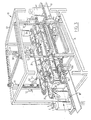
- FIG. 1 shows a top view of an inspection device 10 for successive Inspection of bottles 1.
- the device is included a feed conveyor belt 11 driven by a motor 12 is driven, a discharge conveyor belt 13, the a motor 14 is driven, and an intermediate conveyor 15, between the feed conveyor 11 and the discharge conveyor belt 13 used is.
- a video camera 16 In addition to the feed conveyor belt 11 is a video camera 16 with associated video monitor 17 arranged.
- the camera 16 is an optical one System of four mirrors 18 assigned to the two images from a single video image different angles on the video camera 16 can project. For example, two Viewing angles deviate from each other by approximately 90 °. With transparent bottles 1 can both the front and back of a bottle can be inspected in a single operation.
- Video camera 19 with associated monitor 20 arranged.
- This camera 19 is also a System associated with four mirrors that are identical with the system of mirrors 18 are.
- the video camera 19 observes each bottle 1 at an angle that is 90 ° from that Angle deviates at which the video camera 16 watched the same bottle. In this way can with the arrangement already described the mirror, the two cameras 16, 19 together a clear bottle in one Inspect the run from all sides.
- the bottles 1 are from the intermediate conveyor worn on the collar 3, namely by a pair of upper endless conveyors 21, 22, which the Wear fingers 3 and 5, respectively, and one Pair of lower endless conveyors 23, 24, the fingers Wear 8 and 9 respectively.
- Conveyors 21, 22, 23, 24 are generally referred to as 25 Rolling motors 26, 27, 28 and 29, respectively driven by drives 30, 31, 32 respectively 33 can be controlled from. Get this Control signals from associated programmable Divider 34, 35, 36, 37, which in turn Control signals from a microprocessor 38 and the speed of the feed conveyor belt 11 receive appropriate signals. These speed signals are from one with the drive motor 12 coupled tachometer, not shown generates the pulse series 39 and its pulse frequency for the speed of the motor 12 is representative and thus for the linear velocity of the feed conveyor belt 11.
- a pulse frequency voltage converter 40 converts the signal 39 into a voltage signal, which in turn by a voltage frequency converter 41 in a Frequency signal is converted as a control signal the dividers 34, 35, 36, 37 fed becomes.
- the speed of the intermediate conveyor 15 does not need exactly that of the feed conveyor belt 11 agree. It is enough if the speeds in question are not too strong differ from each other, for example highest by a few percent.
- the circuit with the converters 41 and 42 allows even at extremely low speeds of the feed conveyor belt 11 nevertheless one to get accurate control.
- the output signal of the converter 41 can, depending on the Speed of the conveyor belt 11, for example vary between 0 and 1 MHz.
- the motors 26, 27, 28, 29 can be stepper motors be, whereby a very simple means very high transport accuracy can be realized can.
- the motors can also be servo-controlled be used.
- the microprocessor 38 is previously the effective length of the intermediate conveyor 15 entered. As will be clear, it is with deviating effective lengths of the pairs 21, 22 and 23, 24 of endless conveyors sufficient effective length of the longer of the two pairs in enter the microprocessor as fixed information. Furthermore, the desired rotation angle of the Bottles 1 previously entered into the microprocessor 38 become. In the described embodiment the rotation angle is 90 °.
- microprocessor 38 needs information with respect to the circumferential shape of the bottles 2 received at the level at which the pairs of the endless Attack conveyor 21, 22 or, 23, 24.
- bottles 1 are rotationally symmetrical, it is sufficient if the diameter of the Bottles 1 at the attack height of fingers 4, 5 and 8, 9 is measured according to FIG. 1 and as Information entered into the microprocessor 38 becomes.
- FIG. 2 shows displacement sensors 42, 43, 44 for the lateral position of the endless conveyors 21, 22 or the endless conveyor 23, 24.
- the intermediate conveyor 15 comprises a support frame 49 with four rotatable by means of a handle 50 Screw spindles 51 with which the car 52 interact by operating the Handle can be moved up and down together.
- the wagons 52 in turn carry and guide Screw spindles 53 with two counter-rotating Screw threads, generally designated 54 Interacting wagons.
- the wagons 54 carry the rollers 25 and the motors 26, 27.
- the lower conveyors 23, 24 are in the same Way movable.
- the adjustable construction for the upper conveyor 21, 22 is described in detail.
- the adjustability of the lower conveyor 23, 24 is therefore not discussed with reference to FIG. 3 calmly.
- the vertical position of the lower one Conveyor 23, 24 is fixed.
- Rolls 56 are both at the end of the import as at the end of the intermediate conveyor 15 near the rollers 25. As FIG. 3 clearly shows, becomes a "seeker” and very reliable Introduction of bottles 1 into the intermediate conveyor 15 guaranteed.
Landscapes
- Immunology (AREA)
- Pathology (AREA)
- Life Sciences & Earth Sciences (AREA)
- Chemical & Material Sciences (AREA)
- Analytical Chemistry (AREA)
- Biochemistry (AREA)
- General Health & Medical Sciences (AREA)
- General Physics & Mathematics (AREA)
- Health & Medical Sciences (AREA)
- Physics & Mathematics (AREA)
- Engineering & Computer Science (AREA)
- Mechanical Engineering (AREA)
- Investigating Materials By The Use Of Optical Means Adapted For Particular Applications (AREA)
- Sorting Of Articles (AREA)
- Image Processing (AREA)
- Ultra Sonic Daignosis Equipment (AREA)
- Length Measuring Devices By Optical Means (AREA)
Description
Claims (1)
- Vorrichtung zur fortlaufenden Inspektion zugeführter gleicher, rotationssymmetrischer, durchsichtiger Gegenstände (1),
mit einer Zufuhrförderanlage (11, 12) zur aufeinanderfolgenden Zufuhr der Gegenstände (1);
mit einer neben der Zufuhrförderanlage (11, 12) angeordneten ersten Inspektionsstation (16, 17, 18) zum Inspizieren der zwischen der Rotationsachse und der Inspektionsstation befindlichen Wand und der auf der anderen Seite der Rotationsachse befindlichen Wand der passierenden Gegenstände (1) von der Seite und zur Abgabe eines das Inspektionsergebnis wiedergebenden Inspektionssignals;
mit einer Abfuhrförderanlage (13, 14) zur Abfuhr der Gegenstände (1);
mit einer neben der Abfuhrförderanlage (13, 14) angeordneten zweiten Inspektionsstation (19, 20) zum Inspizieren der zwischen der Rotationsachse und der Inspektionsstation befindlichen Wand und der auf der anderen Seite der Rotationsachse befindlichen Wand der passierenden Gegenstände (1) von der Seite und zur Abgabe eines das Inspektionsergebnis wiedergebenden Inspektionssignals, und
daß dadurch gekennzeichnet, wenigstens zwei Paare von Endlosförderern (21, 22; 23, 24) vosgesehen sind, die jeden der Gegenstände (1) auf beiden Seiten in unterschiedlicher Höhe erfassen, so daß Pendelbewegungen der Gegenstände (1) effektiv vermieden werden, wobei die Endlosförderer (21, 22; 23, 24) jeweils mittels individueller Antriebsmittel (26 bis 29) mit unterschiedlichen Geschwindigkeiten (V1, V2; V3, V4) angetrieben werden, so daß die Gegenstände (1) um einen vorgegebenen Winkel um ihre Symmetrieachse gedreht werden, und die Geschwindigkeiten der Endlosförderer (21, 22; 23, 24) in Abhängigkeit von dem Durchmesser der Gegenstände (1) in Angriffshöhe der Endlosförderer (21, 22; 23, 24), dem Drehwinkel der Gegenstände (1) und der Länge der Endlosförderer (21, 22; 23, 24) gewählt sind,
daß die zwei Paare von Endlosförderern (21, 22; 23, 24) als Zwischenförderanlage (15) zwischen der Zuführförderanlage (11, 12) und der Abfuhrförderanlage (13, 14) angeordnet sind,
daß im Bereich der Zwischenförderanlage (15) eine Einrichtung zur Bodeninspektion in Form einer genan zeitgesteuerten Blitzbelenchtung vorgesehen ist und
daß der vorgegebene Winkel, um den die Gegenstände (1) gedreht werden, 90° beträgt, so daß mittels der beiden Inspektionsstationen (16, 17, 18; 19, 20) ein vollständiges Bild von den Gegenständen erhalten wird.
Priority Applications (1)
| Application Number | Priority Date | Filing Date | Title |
|---|---|---|---|
| DE9007826U DE9007826U1 (de) | 1989-08-10 | 1990-08-10 | Vorrichtung zur Seitenwand- und Bodeninspektion rotationssymmetrischer Gegenstände, insbesondere Flaschen |
Applications Claiming Priority (2)
| Application Number | Priority Date | Filing Date | Title |
|---|---|---|---|
| NL8902041A NL8902041A (nl) | 1989-08-10 | 1989-08-10 | Inrichting voor het vanuit verschillende gezichtshoeken inspecteren van voorwerpen. |
| NL8902041 | 1989-08-10 |
Publications (3)
| Publication Number | Publication Date |
|---|---|
| EP0415154A1 EP0415154A1 (de) | 1991-03-06 |
| EP0415154B1 EP0415154B1 (de) | 1995-04-19 |
| EP0415154B2 true EP0415154B2 (de) | 2001-07-04 |
Family
ID=19855156
Family Applications (1)
| Application Number | Title | Priority Date | Filing Date |
|---|---|---|---|
| EP90115382A Expired - Lifetime EP0415154B2 (de) | 1989-08-10 | 1990-08-10 | Verfahren zum Inspizieren von Gegenständen aus unterschiedlichen Blickwinkeln |
Country Status (6)
| Country | Link |
|---|---|
| EP (1) | EP0415154B2 (de) |
| AT (1) | ATE121319T1 (de) |
| DE (2) | DE59008922D1 (de) |
| DK (1) | DK0415154T4 (de) |
| ES (1) | ES2074502T5 (de) |
| NL (1) | NL8902041A (de) |
Cited By (1)
| Publication number | Priority date | Publication date | Assignee | Title |
|---|---|---|---|---|
| CN109642874A (zh) * | 2017-08-09 | 2019-04-16 | 克朗斯股份公司 | 用以对用于容器的检查模块进行紧固的框和检查装置 |
Families Citing this family (31)
| Publication number | Priority date | Publication date | Assignee | Title |
|---|---|---|---|---|
| DE4022733C1 (en) * | 1989-12-19 | 1991-05-08 | Elpatronic Ag, Zug, Ch | Three=dimensional cavity inspection appts. - uses matrix or line camera to receive reflected light via gp. of four mirrors and deflecting mirror |
| DE9310623U1 (de) * | 1993-07-16 | 1993-11-11 | Krones Ag Hermann Kronseder Maschinenfabrik, 93073 Neutraubling | Inspektionsmaschine für Flaschen o.dgl. |
| EP0642995A1 (de) * | 1993-09-15 | 1995-03-15 | Emhart Glass Machinery Investments Inc. | Vorrichtung zur Handhabung von verjüngten Behältern |
| US5366096A (en) * | 1993-11-17 | 1994-11-22 | Brown & Williamson Tobacco Corp. | Apparatus for and method of automatically detecting and eliminating cigarettes with visual defects during cigarette manufacture |
| CH686910A5 (de) * | 1994-02-24 | 1996-07-31 | Elpatronic Ag | Verfahren und Vorrichtung zur Pruefung der Seitenwand eines Behaelters. |
| US5486692A (en) * | 1994-10-19 | 1996-01-23 | Emhart Glass Machinery Investments Inc. | Glassware inspection machine comprising diffused light sources and two-dimensional cameras |
| DE29518628U1 (de) | 1995-11-24 | 1997-04-10 | Heuft Systemtechnik Gmbh, 56659 Burgbrohl | Vorrichtung zum Drehen von rotationssymmetrischen Behältern wie Flaschen während des Transports unter Staudruck |
| DE29518639U1 (de) * | 1995-11-24 | 1997-03-27 | Heuft Systemtechnik Gmbh | Vorrichtung zum Transportieren von Behältern vorbei an einer Einrichtung zum Inspizieren des Bodens der Behälter |
| DE29600902U1 (de) | 1996-01-19 | 1997-05-15 | Heuft Systemtechnik Gmbh, 56659 Burgbrohl | Vorrichtung zur Inspektion von Gegenständen, insbesondere Getränkeflaschen |
| DE19605133C2 (de) * | 1996-02-13 | 2000-06-15 | Krones Ag | Inspektionsmaschine für Gefäße |
| IL118123A0 (en) * | 1996-05-02 | 1996-09-12 | Farkas Shmuel | Conveyor propulsion system |
| EP0979153A4 (de) * | 1996-06-04 | 2002-10-30 | Inex Inc Doing Business As Ine | System und verfahren zur spannungsdetektion in einem blasgeformten behälter |
| US6109426A (en) * | 1996-11-13 | 2000-08-29 | Simplimatic Engineering Company | Oriented bottle conveyor |
| EP0897760B1 (de) | 1997-07-29 | 2003-07-02 | Marco Lottici | Trnasportvorrichtung in einem Behälterinspektionssystem |
| DE29716795U1 (de) * | 1997-09-18 | 1999-01-28 | Heuft Systemtechnik Gmbh, 56659 Burgbrohl | Vorrichtung zum Ausrichten von rotationssymmetrischen Gegenständen um ihre Längsachse während des Transports |
| US6260425B1 (en) * | 1997-11-04 | 2001-07-17 | Krones Ag Hermann Kronseder Maschinenfabrik | Inspection machine for bottles or similar |
| FR2784665B1 (fr) * | 1998-10-14 | 2001-01-26 | Xeda International | Station d'examen visuel de fruits |
| DE19916703A1 (de) * | 1999-04-14 | 2000-10-19 | Haering Franz | Inspektionsmaschine für transparente Behälter |
| DE29913462U1 (de) | 1999-07-31 | 1999-10-28 | KRONES AG, 93073 Neutraubling | Fördervorrichtung |
| EP1829621B1 (de) * | 2006-03-03 | 2011-05-25 | Machinefabriek Bollegraaf Appingedam B.V. | Vorrichtung und Verfahren zum Sortieren von Abfall |
| DE202007015411U1 (de) | 2007-11-07 | 2008-06-26 | Filtec Europe Gmbh | Vorrichtung zur Inspektion von Behältern |
| DE102008017427B4 (de) * | 2008-04-03 | 2014-02-13 | Khs Gmbh | Vorrichtung sowie Verfahren zur Inspektion von Flaschen oder dergleichen Behältern |
| GB2482473A (en) * | 2010-06-29 | 2012-02-08 | Constar Internat Uk Ltd | Inspection of articles |
| DE102011106133A1 (de) | 2011-06-10 | 2012-12-13 | Krones Aktiengesellschaft | Vorrichtung zum Transportieren von Behältnissen mit Direktantrieb |
| DE102013207138B4 (de) | 2013-04-19 | 2022-12-22 | Krones Aktiengesellschaft | Verfahren und Vorrichtung zur Förderung und Handhabung von Gebinden mit wenigstens zwei umreiften Artikeln |
| DE102013209451A1 (de) | 2013-05-22 | 2014-11-27 | Krones Ag | Inspektionsmaschine für Behälter und Verfahren zum Umlenken von Behältern aus einer ersten in eine zweite Transportrichtung |
| DE102013215794A1 (de) * | 2013-08-09 | 2015-02-12 | Krones Ag | Vorrichtung und Verfahren zum Ausrichten von unrunden Behältern |
| ITPR20130104A1 (it) * | 2013-12-20 | 2015-06-21 | One Love Di Tarasconi Ermina & C S A S | Sperlatrice e metodo di ispezione |
| DE102014005650A1 (de) | 2014-04-17 | 2015-10-22 | Heuft Systemtechnik Gmbh | Behälterinspektion |
| DE102014226965A1 (de) | 2014-12-23 | 2016-06-23 | Krones Ag | Vorrichtung und Verfahren zur fortlaufenden Inspektion von Behältern |
| DE202017107845U1 (de) * | 2017-12-21 | 2019-01-08 | Krones Ag | Behälterorientierung über eine Schnecke |
Family Cites Families (3)
| Publication number | Priority date | Publication date | Assignee | Title |
|---|---|---|---|---|
| JPS5546172A (en) * | 1978-09-29 | 1980-03-31 | Kirin Brewery Co Ltd | Detector for foreign material |
| NL8303007A (nl) * | 1983-04-22 | 1984-11-16 | Thomassen & Drijver | Inrichting voor het controleren van houders. |
| US4691231A (en) * | 1985-10-01 | 1987-09-01 | Vistech Corporation | Bottle inspection system |
-
1989
- 1989-08-10 NL NL8902041A patent/NL8902041A/nl not_active Application Discontinuation
-
1990
- 1990-08-10 EP EP90115382A patent/EP0415154B2/de not_active Expired - Lifetime
- 1990-08-10 AT AT90115382T patent/ATE121319T1/de not_active IP Right Cessation
- 1990-08-10 DE DE59008922T patent/DE59008922D1/de not_active Expired - Lifetime
- 1990-08-10 ES ES90115382T patent/ES2074502T5/es not_active Expired - Lifetime
- 1990-08-10 DK DK90115382T patent/DK0415154T4/da active
- 1990-08-10 DE DE9007826U patent/DE9007826U1/de not_active Expired - Lifetime
Cited By (2)
| Publication number | Priority date | Publication date | Assignee | Title |
|---|---|---|---|---|
| CN109642874A (zh) * | 2017-08-09 | 2019-04-16 | 克朗斯股份公司 | 用以对用于容器的检查模块进行紧固的框和检查装置 |
| CN109642874B (zh) * | 2017-08-09 | 2022-06-17 | 克朗斯股份公司 | 用以对用于容器的检查模块进行紧固的框和检查装置 |
Also Published As
| Publication number | Publication date |
|---|---|
| EP0415154B1 (de) | 1995-04-19 |
| DE9007826U1 (de) | 1997-07-24 |
| NL8902041A (nl) | 1991-03-01 |
| DK0415154T3 (da) | 1995-06-26 |
| ES2074502T5 (es) | 2001-12-16 |
| DK0415154T4 (da) | 2001-09-17 |
| ATE121319T1 (de) | 1995-05-15 |
| ES2074502T3 (es) | 1995-09-16 |
| DE59008922D1 (de) | 1995-05-24 |
| EP0415154A1 (de) | 1991-03-06 |
Similar Documents
| Publication | Publication Date | Title |
|---|---|---|
| EP0415154B2 (de) | Verfahren zum Inspizieren von Gegenständen aus unterschiedlichen Blickwinkeln | |
| EP0433666B1 (de) | Vorrichtung zur dreidimensionalen Inspektion von Hohlkörpern | |
| EP1130384A1 (de) | Inspektionsmaschine | |
| EP1811289B1 (de) | Verfahren sowie Vorrichtung zur Inspektion von Flaschen oder dgl. Behälter | |
| EP0874699B1 (de) | Vorrichtung und verfahren zur inspektion von gegenständen, insbesondere getränkeflaschen | |
| DE9310623U1 (de) | Inspektionsmaschine für Flaschen o.dgl. | |
| DE60224623T2 (de) | Wanddickenmessung eines transparenten Behälters mit einem Lichtfächer | |
| DE2530886C3 (de) | Vorrichtung zum Ordnen vereinzelter, in entgegengesetzten Richtungen ungeordnet orientierter Gegenstände | |
| EP0349823A1 (de) | Verfahren und Vorrichtung zur Überprüfung von Zigaretten | |
| EP0528197B1 (de) | Verfahren und Vorrichtung zur Inspektion von Tabletten | |
| EP0816230A1 (de) | Verfahren und Vorrichtung zum opto-elektrischen Abtasten von Verpackungen, insbesondere Zigaretten-Packungen | |
| DE69430678T2 (de) | Anordnung zur Kontrolle von Hohlglasbehältern | |
| DE69114450T2 (de) | Verfahren und Vorrichtung zur Abbildung mit bewegungsfolgendem Spiegel. | |
| DE9313115U1 (de) | Inspektionsmaschine | |
| DE102004047848A1 (de) | Verfahren und Vorrichtung zum Sortieren von vereinzelten Prüflingen mittels Bildverarbeitung | |
| EP0463566B2 (de) | Verfahren und Vorrichtung zur Trefferauswertung von Schiessscheiben | |
| EP3577445B1 (de) | Inspektionsvorrichtung und -verfahren zur seitenwand- und verschlusskopfinspektion von behältern | |
| DE1648459B2 (de) | Vorrichtung zum Zuführen von zylindrischen Glaskörpern zu einer Kontrollstation | |
| EP1568625B1 (de) | Inspektionsmaschine mit einer Vorrichtung zum Transportieren von Hohlkörpern | |
| DE4300729A1 (de) | ||
| EP0623835B1 (de) | Verfahren und Anordnung zum Winkeljustieren einer Linienabtastvorrichtung | |
| DE3605234C2 (de) | ||
| DE19845938C1 (de) | Vorrichtung zum Sortieren und/oder Klassifizieren von stangenförmigem Gemüse | |
| DE19618503A1 (de) | Vorrichtung zur dynamischen Erfassung des Gewichts sowie der Geometrie und/oder der Lage von Stückgütern | |
| EP0913683B1 (de) | Vorrichtung zur Prüfung nicht-rotationssymmetrischer Hohlkörper auf Defekte |
Legal Events
| Date | Code | Title | Description |
|---|---|---|---|
| PUAI | Public reference made under article 153(3) epc to a published international application that has entered the european phase |
Free format text: ORIGINAL CODE: 0009012 |
|
| AK | Designated contracting states |
Kind code of ref document: A1 Designated state(s): AT BE CH DE DK ES FR GB GR IT LI NL SE |
|
| 17P | Request for examination filed |
Effective date: 19910904 |
|
| RAP1 | Party data changed (applicant data changed or rights of an application transferred) |
Owner name: HEUFT SYSTEMTECHNIK GMBH |
|
| 17Q | First examination report despatched |
Effective date: 19921022 |
|
| GRAA | (expected) grant |
Free format text: ORIGINAL CODE: 0009210 |
|
| AK | Designated contracting states |
Kind code of ref document: B1 Designated state(s): AT BE CH DE DK ES FR GB GR IT LI NL SE |
|
| PG25 | Lapsed in a contracting state [announced via postgrant information from national office to epo] |
Ref country code: GR Free format text: LAPSE BECAUSE OF FAILURE TO SUBMIT A TRANSLATION OF THE DESCRIPTION OR TO PAY THE FEE WITHIN THE PRESCRIBED TIME-LIMIT Effective date: 19950419 |
|
| REF | Corresponds to: |
Ref document number: 121319 Country of ref document: AT Date of ref document: 19950515 Kind code of ref document: T |
|
| ITF | It: translation for a ep patent filed | ||
| REF | Corresponds to: |
Ref document number: 59008922 Country of ref document: DE Date of ref document: 19950524 |
|
| REG | Reference to a national code |
Ref country code: DK Ref legal event code: T3 |
|
| ET | Fr: translation filed | ||
| GBT | Gb: translation of ep patent filed (gb section 77(6)(a)/1977) |
Effective date: 19950728 |
|
| REG | Reference to a national code |
Ref country code: ES Ref legal event code: FG2A Ref document number: 2074502 Country of ref document: ES Kind code of ref document: T3 |
|
| PLBQ | Unpublished change to opponent data |
Free format text: ORIGINAL CODE: EPIDOS OPPO |
|
| PLBI | Opposition filed |
Free format text: ORIGINAL CODE: 0009260 |
|
| PLBF | Reply of patent proprietor to notice(s) of opposition |
Free format text: ORIGINAL CODE: EPIDOS OBSO |
|
| 26 | Opposition filed |
Opponent name: KRONES AG HERMANN KRONSEDER MASCHINENFABRIK Effective date: 19960119 |
|
| NLR1 | Nl: opposition has been filed with the epo |
Opponent name: KRONES AG HERMANN KRONSEDER MASCHINENFABRIK |
|
| PLBF | Reply of patent proprietor to notice(s) of opposition |
Free format text: ORIGINAL CODE: EPIDOS OBSO |
|
| PLBF | Reply of patent proprietor to notice(s) of opposition |
Free format text: ORIGINAL CODE: EPIDOS OBSO |
|
| PLBQ | Unpublished change to opponent data |
Free format text: ORIGINAL CODE: EPIDOS OPPO |
|
| PLBI | Opposition filed |
Free format text: ORIGINAL CODE: 0009260 |
|
| 26 | Opposition filed |
Opponent name: KRONES AG HERMANN KRONSEDER MASCHINENFABRIK Effective date: 19960119 Opponent name: MIHO AUTOMATISATIONSTECHNIK GMBH Effective date: 19970313 |
|
| NLR1 | Nl: opposition has been filed with the epo |
Opponent name: KRONES AG HERMANN KRONSEDER MASCHINENFABRIK Opponent name: MIHO AUTOMATISATIONSTECHNIK GMBH |
|
| RDAH | Patent revoked |
Free format text: ORIGINAL CODE: EPIDOS REVO |
|
| APAC | Appeal dossier modified |
Free format text: ORIGINAL CODE: EPIDOS NOAPO |
|
| APAE | Appeal reference modified |
Free format text: ORIGINAL CODE: EPIDOS REFNO |
|
| APAC | Appeal dossier modified |
Free format text: ORIGINAL CODE: EPIDOS NOAPO |
|
| APAC | Appeal dossier modified |
Free format text: ORIGINAL CODE: EPIDOS NOAPO |
|
| PLAW | Interlocutory decision in opposition |
Free format text: ORIGINAL CODE: EPIDOS IDOP |
|
| PUAH | Patent maintained in amended form |
Free format text: ORIGINAL CODE: 0009272 |
|
| STAA | Information on the status of an ep patent application or granted ep patent |
Free format text: STATUS: PATENT MAINTAINED AS AMENDED |
|
| 27A | Patent maintained in amended form |
Effective date: 20010704 |
|
| AK | Designated contracting states |
Kind code of ref document: B2 Designated state(s): AT BE CH DE DK ES FR GB GR IT LI NL SE |
|
| ITF | It: translation for a ep patent filed | ||
| REG | Reference to a national code |
Ref country code: CH Ref legal event code: AEN Free format text: AUFRECHTERHALTUNG DES PATENTES IN GEAENDERTER FORM |
|
| NLR2 | Nl: decision of opposition | ||
| REG | Reference to a national code |
Ref country code: DK Ref legal event code: T4 |
|
| GBTA | Gb: translation of amended ep patent filed (gb section 77(6)(b)/1977) | ||
| NLR3 | Nl: receipt of modified translations in the netherlands language after an opposition procedure | ||
| ET3 | Fr: translation filed ** decision concerning opposition | ||
| REG | Reference to a national code |
Ref country code: ES Ref legal event code: DC2A Kind code of ref document: T5 Effective date: 20011002 |
|
| REG | Reference to a national code |
Ref country code: GB Ref legal event code: IF02 |
|
| REG | Reference to a national code |
Ref country code: CH Ref legal event code: NV Representative=s name: SERVOPATENT GMBH |
|
| APAH | Appeal reference modified |
Free format text: ORIGINAL CODE: EPIDOSCREFNO |
|
| REG | Reference to a national code |
Ref country code: FR Ref legal event code: ST Effective date: 20070430 |
|
| REG | Reference to a national code |
Ref country code: CH Ref legal event code: PFA Owner name: HEUFT SYSTEMTECHNIK GMBH Free format text: HEUFT SYSTEMTECHNIK GMBH#BROHLTALSTRASSE 29-33#D-56659 BURGBROHL (DE) -TRANSFER TO- HEUFT SYSTEMTECHNIK GMBH#BROHLTALSTRASSE 29-33#D-56659 BURGBROHL (DE) |
|
| PGFP | Annual fee paid to national office [announced via postgrant information from national office to epo] |
Ref country code: FR Payment date: 20090819 Year of fee payment: 20 Ref country code: ES Payment date: 20090821 Year of fee payment: 20 Ref country code: DK Payment date: 20090821 Year of fee payment: 20 |
|
| PGFP | Annual fee paid to national office [announced via postgrant information from national office to epo] |
Ref country code: SE Payment date: 20090821 Year of fee payment: 20 Ref country code: DE Payment date: 20090731 Year of fee payment: 20 Ref country code: GB Payment date: 20090821 Year of fee payment: 20 Ref country code: NL Payment date: 20090820 Year of fee payment: 20 Ref country code: CH Payment date: 20090824 Year of fee payment: 20 Ref country code: AT Payment date: 20090820 Year of fee payment: 20 |
|
| PGFP | Annual fee paid to national office [announced via postgrant information from national office to epo] |
Ref country code: BE Payment date: 20090821 Year of fee payment: 20 |
|
| PGFP | Annual fee paid to national office [announced via postgrant information from national office to epo] |
Ref country code: IT Payment date: 20090825 Year of fee payment: 20 |
|
| REG | Reference to a national code |
Ref country code: CH Ref legal event code: PL |
|
| REG | Reference to a national code |
Ref country code: NL Ref legal event code: V4 Effective date: 20100810 |
|
| REG | Reference to a national code |
Ref country code: DK Ref legal event code: EUP |
|
| BE20 | Be: patent expired |
Owner name: *HEUFT SYSTEMTECHNIK G.M.B.H. Effective date: 20100810 |
|
| REG | Reference to a national code |
Ref country code: GB Ref legal event code: PE20 Expiry date: 20100809 |
|
| EUG | Se: european patent has lapsed | ||
| REG | Reference to a national code |
Ref country code: ES Ref legal event code: FD2A Effective date: 20100811 |
|
| PG25 | Lapsed in a contracting state [announced via postgrant information from national office to epo] |
Ref country code: NL Free format text: LAPSE BECAUSE OF EXPIRATION OF PROTECTION Effective date: 20100810 |
|
| PG25 | Lapsed in a contracting state [announced via postgrant information from national office to epo] |
Ref country code: GB Free format text: LAPSE BECAUSE OF EXPIRATION OF PROTECTION Effective date: 20100809 |
|
| PG25 | Lapsed in a contracting state [announced via postgrant information from national office to epo] |
Ref country code: DE Free format text: LAPSE BECAUSE OF EXPIRATION OF PROTECTION Effective date: 20100810 |