EP0410306B1 - Verfahren und Vorrichtung zur Sterilisation von Müll, insbesondere Krankenhausmüll - Google Patents
Verfahren und Vorrichtung zur Sterilisation von Müll, insbesondere Krankenhausmüll Download PDFInfo
- Publication number
- EP0410306B1 EP0410306B1 EP90113871A EP90113871A EP0410306B1 EP 0410306 B1 EP0410306 B1 EP 0410306B1 EP 90113871 A EP90113871 A EP 90113871A EP 90113871 A EP90113871 A EP 90113871A EP 0410306 B1 EP0410306 B1 EP 0410306B1
- Authority
- EP
- European Patent Office
- Prior art keywords
- refuse
- sterilising
- chamber
- container
- containers
- Prior art date
- Legal status (The legal status is an assumption and is not a legal conclusion. Google has not performed a legal analysis and makes no representation as to the accuracy of the status listed.)
- Expired - Lifetime
Links
- 238000004659 sterilization and disinfection Methods 0.000 title claims abstract description 89
- 238000000034 method Methods 0.000 title claims abstract description 30
- 230000008569 process Effects 0.000 title claims abstract description 22
- 239000002699 waste material Substances 0.000 title abstract description 65
- 239000002906 medical waste Substances 0.000 title abstract description 16
- 238000002347 injection Methods 0.000 claims abstract description 66
- 239000007924 injection Substances 0.000 claims abstract description 66
- XLYOFNOQVPJJNP-UHFFFAOYSA-N water Substances O XLYOFNOQVPJJNP-UHFFFAOYSA-N 0.000 claims abstract description 45
- 239000000645 desinfectant Substances 0.000 claims abstract description 19
- 230000001954 sterilising effect Effects 0.000 claims description 115
- 239000007789 gas Substances 0.000 claims description 14
- 238000007789 sealing Methods 0.000 claims description 9
- 238000010438 heat treatment Methods 0.000 claims description 8
- 230000007246 mechanism Effects 0.000 claims description 8
- -1 polyethylene Polymers 0.000 claims description 6
- 238000003780 insertion Methods 0.000 claims description 5
- 230000037431 insertion Effects 0.000 claims description 5
- 239000007788 liquid Substances 0.000 claims description 4
- 239000000523 sample Substances 0.000 claims description 4
- 210000002105 tongue Anatomy 0.000 claims description 4
- 239000004698 Polyethylene Substances 0.000 claims description 3
- 239000004743 Polypropylene Substances 0.000 claims description 3
- 239000013013 elastic material Substances 0.000 claims description 3
- 229920000573 polyethylene Polymers 0.000 claims description 3
- 229920001155 polypropylene Polymers 0.000 claims description 3
- 238000009434 installation Methods 0.000 claims 24
- 230000005484 gravity Effects 0.000 claims 6
- 238000009530 blood pressure measurement Methods 0.000 claims 3
- 238000009529 body temperature measurement Methods 0.000 claims 2
- 230000006835 compression Effects 0.000 claims 1
- 238000007906 compression Methods 0.000 claims 1
- 239000004033 plastic Substances 0.000 abstract description 34
- 229920003023 plastic Polymers 0.000 abstract description 34
- 229920006395 saturated elastomer Polymers 0.000 abstract 1
- 238000002360 preparation method Methods 0.000 description 9
- 244000052616 bacterial pathogen Species 0.000 description 7
- 230000002458 infectious effect Effects 0.000 description 6
- 239000000463 material Substances 0.000 description 5
- OKTJSMMVPCPJKN-UHFFFAOYSA-N Carbon Chemical compound [C] OKTJSMMVPCPJKN-UHFFFAOYSA-N 0.000 description 4
- 239000010781 infectious medical waste Substances 0.000 description 4
- 238000013461 design Methods 0.000 description 3
- 238000010276 construction Methods 0.000 description 2
- 230000000249 desinfective effect Effects 0.000 description 2
- 201000010099 disease Diseases 0.000 description 2
- 208000037265 diseases, disorders, signs and symptoms Diseases 0.000 description 2
- 208000015181 infectious disease Diseases 0.000 description 2
- 238000012986 modification Methods 0.000 description 2
- 230000004048 modification Effects 0.000 description 2
- 241001136792 Alle Species 0.000 description 1
- 241000894006 Bacteria Species 0.000 description 1
- 230000008901 benefit Effects 0.000 description 1
- 230000015572 biosynthetic process Effects 0.000 description 1
- 230000009172 bursting Effects 0.000 description 1
- 238000011109 contamination Methods 0.000 description 1
- 238000011161 development Methods 0.000 description 1
- 230000018109 developmental process Effects 0.000 description 1
- 230000000694 effects Effects 0.000 description 1
- 230000005284 excitation Effects 0.000 description 1
- 230000036541 health Effects 0.000 description 1
- 230000001678 irradiating effect Effects 0.000 description 1
- 238000005259 measurement Methods 0.000 description 1
- 239000003595 mist Substances 0.000 description 1
- 238000002156 mixing Methods 0.000 description 1
- 238000002663 nebulization Methods 0.000 description 1
- 239000006199 nebulizer Substances 0.000 description 1
- 230000000149 penetrating effect Effects 0.000 description 1
- 238000003825 pressing Methods 0.000 description 1
- 230000005855 radiation Effects 0.000 description 1
- 230000009467 reduction Effects 0.000 description 1
- 230000001105 regulatory effect Effects 0.000 description 1
- 239000012858 resilient material Substances 0.000 description 1
- 239000000243 solution Substances 0.000 description 1
Images

Classifications
-
- A—HUMAN NECESSITIES
- A61—MEDICAL OR VETERINARY SCIENCE; HYGIENE
- A61L—METHODS OR APPARATUS FOR STERILISING MATERIALS OR OBJECTS IN GENERAL; DISINFECTION, STERILISATION OR DEODORISATION OF AIR; CHEMICAL ASPECTS OF BANDAGES, DRESSINGS, ABSORBENT PADS OR SURGICAL ARTICLES; MATERIALS FOR BANDAGES, DRESSINGS, ABSORBENT PADS OR SURGICAL ARTICLES
- A61L11/00—Methods specially adapted for refuse
-
- A—HUMAN NECESSITIES
- A61—MEDICAL OR VETERINARY SCIENCE; HYGIENE
- A61L—METHODS OR APPARATUS FOR STERILISING MATERIALS OR OBJECTS IN GENERAL; DISINFECTION, STERILISATION OR DEODORISATION OF AIR; CHEMICAL ASPECTS OF BANDAGES, DRESSINGS, ABSORBENT PADS OR SURGICAL ARTICLES; MATERIALS FOR BANDAGES, DRESSINGS, ABSORBENT PADS OR SURGICAL ARTICLES
- A61L2/00—Methods or apparatus for disinfecting or sterilising materials or objects other than foodstuffs or contact lenses; Accessories therefor
- A61L2/02—Methods or apparatus for disinfecting or sterilising materials or objects other than foodstuffs or contact lenses; Accessories therefor using physical phenomena
- A61L2/04—Heat
- A61L2/06—Hot gas
-
- A—HUMAN NECESSITIES
- A61—MEDICAL OR VETERINARY SCIENCE; HYGIENE
- A61L—METHODS OR APPARATUS FOR STERILISING MATERIALS OR OBJECTS IN GENERAL; DISINFECTION, STERILISATION OR DEODORISATION OF AIR; CHEMICAL ASPECTS OF BANDAGES, DRESSINGS, ABSORBENT PADS OR SURGICAL ARTICLES; MATERIALS FOR BANDAGES, DRESSINGS, ABSORBENT PADS OR SURGICAL ARTICLES
- A61L2/00—Methods or apparatus for disinfecting or sterilising materials or objects other than foodstuffs or contact lenses; Accessories therefor
- A61L2/02—Methods or apparatus for disinfecting or sterilising materials or objects other than foodstuffs or contact lenses; Accessories therefor using physical phenomena
- A61L2/08—Radiation
- A61L2/12—Microwaves
-
- A—HUMAN NECESSITIES
- A61—MEDICAL OR VETERINARY SCIENCE; HYGIENE
- A61L—METHODS OR APPARATUS FOR STERILISING MATERIALS OR OBJECTS IN GENERAL; DISINFECTION, STERILISATION OR DEODORISATION OF AIR; CHEMICAL ASPECTS OF BANDAGES, DRESSINGS, ABSORBENT PADS OR SURGICAL ARTICLES; MATERIALS FOR BANDAGES, DRESSINGS, ABSORBENT PADS OR SURGICAL ARTICLES
- A61L2/00—Methods or apparatus for disinfecting or sterilising materials or objects other than foodstuffs or contact lenses; Accessories therefor
- A61L2/16—Methods or apparatus for disinfecting or sterilising materials or objects other than foodstuffs or contact lenses; Accessories therefor using chemical substances
- A61L2/18—Liquid substances or solutions comprising solids or dissolved gases
Definitions
- the invention relates to a method and a device for the sterilization of waste, in particular hospital waste, using a number of disposable waste containers which are hermetically sealed after loading with waste and are then preferably introduced to several in a sterilization tunnel and then irradiated with microwaves are, either before or during the microwave irradiation, water or a disinfectant is introduced into the garbage of the garbage container and the garbage container (s) are then discharged from the sterilization tunnel at a discharge point.
- a container for holding infectious waste, in particular hospital waste is known.
- this waste is sterilized with the aid of microwaves, which is possible because the container, which can be closed from the outside, consists of a material through which microwaves can pass.
- the inside of this container is equipped with an insertable, stable and closable disposable inner container for the infectious waste, which consists of an essentially moisture-proof, but also vapor and / or microwave permeable tear-resistant material.
- the outer container of this arrangement can be designed as a pressure container.
- a bag or the like with liquid, preferably disinfectant, can be attached to the inside of the lid of said inner container.
- liquid preferably disinfectant
- the liquid inside the bag is heated, partially evaporates, which ultimately bursts the bag and empties its contents into the surrounding garbage.
- EP 0 049 430 describes a bulk container with a lid, preferably for use as a disposable transport container, known that can also be used for the reception of hospital waste.
- DE-OS 29 08 086 a method for disinfecting and sterilizing objects contaminated with germs is known, whereby this known method consists in that a disinfectant is atomized in the space around the object to be treated. This known method can also be further developed in that the object surrounded by the disinfectant is irradiated with microwaves. The disinfection process takes place in a closed and sealed disinfection chamber, a nebulizer for disinfectants being arranged within the disinfection chamber.
- a further embodiment of this disinfection chamber consists in that a microwave device is provided in the same and a control device is provided outside the disinfection chamber, with which the nebulization device is switched on first and only after the formation of a disinfection mist in the disinfection chamber the microwave device is switched on.
- a disinfection chamber which can also be constructed in the form of a sterilization tunnel, with several microwave generators being arranged in succession on the walls of the tunnel, it is possible, if the garbage is introduced directly into the chamber, for germs to escape from this chamber or tunnel can, for example when a swipe occurs, d. H. the germs or bacteria to be killed cannot happen to be kept in the chamber or in the tunnel sufficiently long, so that 100% sterilization and disinfection cannot be achieved with great certainty.
- DE 37 10 156 A1 discloses a device for treating infectious waste with the aid of microwaves.
- the Known device comprises a microwave chamber into which containers filled with the infectious waste, which are hermetically sealed with the aid of a lid, are introduced.
- the container consists of microwave-permeable material and in the microwave chamber itself a device is provided for moving the container during the irradiation with microwaves.
- This device can be, for example, a conveyor belt or a turntable.
- the containers themselves can have another container for holding a liquid, in particular water, on the inside.
- DE 35 05 571 C2 discloses a device for disinfecting and sterilizing mattresses or the like with the aid of microwaves, which has a microwave chamber for receiving the mattresses and at least one microwave transmitter for irradiating the moistened mattresses.
- the essence of this known device is that the microwave chamber, which is closed on all sides, has microwave-permeable windows through which microwaves are radiated into the microwave chamber, that a microwave-permeable mattress chamber is accommodated within the microwave chamber, and that the microwave chamber and the mattress chamber communicate with one another, the microwave chamber communicating with the Mattress chamber is designed as a lock and lock doors are provided on both sides of the mattress chamber.
- the object on which the invention is based is to provide a method and a device for sterilizing waste, in particular to create hospital waste of the type specified, in which or in which the sterilization can be carried out with a very high degree of security and in particular always ensures that water reaches the waste container in question independently of the attention of an operator.
- the method according to the present invention can be carried out under Ensuring a high level of security against contamination of the immediate surroundings of the sterilization system, while always ensuring that water or a disinfectant is present inside the waste container.
- the invention can experience an advantageous embodiment in that the injection needles in the sterilization chamber are lowered from top to bottom onto the respective waste container in order to pierce the respective lid of the waste container.
- the injection needles are held in position during the microwave treatment in their punctured state.
- An advantageous embodiment of the invention also consists in that more than one injection needle is inserted into each waste container. It is possible to use one of the injection needles to introduce water or a disinfectant into the waste container, while a second needle can be used to discharge air or any gases inside the waste container to prevent excess pressure from developing inside the waste container prevent.
- the extracted gas can be sent through a sterilization circuit and then either released into the atmosphere or introduced into the sterilization chamber.
- the injection needles can be used to inject preferably heated water vapor into the garbage container.
- the gas extracted from the respective waste container can be passed through a filter, a heating area and / or a microwave radiation area in order to also sterilize it.
- the lock door between the lock chamber and the sterilization chamber is hermetically locked when the discharge door of the sterilization chamber or the entry door of the lock chamber is opened and furthermore the lock door is only unlocked, when the sterilization chamber discharge door is closed and the lock chamber entry door is closed.
- the invention also relates to a device for carrying out the method according to the invention, which comprises a sterilization tunnel which has a sterilization chamber with an insertion end and a discharge end and a conveyor belt.
- the invention also relates to a device for sterilizing waste, in particular hospital waste, with a plurality of waste containers which can be closed by a lid and penetrated by an injection needle and which are suitable for the sterilization of waste contained therein in a microwave sterilization tunnel, which has at least one conveyor track for contains simultaneous conveyance of a plurality of waste containers arranged one behind the other and which has an injection device in order to inject water or a disinfectant into a number of waste containers preferably simultaneously.
- this device for sterilizing waste in particular hospital waste, is designed so that it can be carried out in a particularly compact design and always ensures that the injection needle in question is inserted into the container at a precisely defined target injection point, thereby creating a to achieve greater security when sealing the garbage container.
- At least one conveyor track is formed from a roller conveyor track which is inclined downward from the entry end to the discharge end of the sterilization tunnel, so that the waste containers placed or suspended on the roller conveyor track are thereby conveyed towards the discharge end of the sterilization tunnel due to their own weight.
- the garbage containers are each provided near their top with a circumferential flange, with the aid of which the garbage containers are placed on and carried by the at least one roller conveyor.
- the refuse containers are each equipped with a target puncture site, which consists of a wall section which closes the puncture of an injection needle.
- the invention can have an advantageous embodiment in that two roller conveyor tracks are arranged parallel to one another in the sterilization tunnel.
- a releasable stop is expediently provided at the discharge end of the respective roller conveyor track, up to which the first waste container entered in the sterilization tunnel can roll.
- the inclination of the respective roller conveyor is dimensioned such that the garbage containers lined up in the respective roller conveyor roll due to their own weight in the direction of the discharge end of the sterilization tunnel, the foremost garbage container being supported on the releasable stop and the subsequent garbage containers being supported against one another, so that thereby a continuous, uninterrupted row of containers is formed.
- the advantage is also achieved that the waste containers are positioned exactly relative to each other on the respective roller conveyor so that the injection needles can be inserted at a precisely defined point on the container.
- a cross conveyor belt can also be arranged at the discharge end of the sterilization tunnel in order to then convey the waste containers discharged from the sterilization tunnel to a pressurized waste container.
- a small lock chamber can also be arranged at the entry end of the sterilization tunnel.
- the sterilization tunnel can itself be arranged to be movable and installed, for example, on a truck or truck trailer.
- the garbage containers are advantageously approximately square or rectangular in plan view and have rounded corners.
- the circumferential flange of the respective refuse container has openings which are arranged at intervals from one another and through which locking tongues formed on the cover of the refuse container can be inserted in order to lock the cover on the circumferential flange.
- the circumferential flange thus has two different functions, namely that it serves on the one hand to support and hold the waste container on the respective roller conveyor and on the other hand serves to achieve a secure closure between the lid and the waste container.
- the cover has a circumferential groove which receives the upper container edge and in which a sealing element for sealing the cover is arranged on the container edge.
- This sealing element is preferably made of an elastic material, such as rubber, so that the locking process can be carried out easily and quickly.
- the invention can also experience an advantageous embodiment in that the wall section defining the desired puncture site is formed on the lid of the waste container and consists of a wedge-shaped narrowing wall recess, the line of contact of the wedge-shaped walls on the bottom of the depression forming the puncture site .
- the wall sections touching one another at the bottom of the depression are connected to one another in one piece, so that this area is completely sealed and any gases cannot escape from the inside of the refuse container there.
- the wedge-shaped converging wall sections advantageously merge into one extended wall extension, which points to the inside of the container.
- the wall extension can expediently run into a thinned wall extension edge, as a result of which a very specific sealing effect is achieved.
- a recess serving as a water reservoir can also be formed in the bottom of the respective waste container.
- each of the injection needles can also be connected to a temperature and pressure measuring device.
- the pressure measuring device can, for example, be integrated in the line system of the water supply.
- the pressure measuring device can be provided centrally on the water distribution system, a main water line being provided, from which the individual water supply lines branch off to the injection needles.
- the injection needle itself consists of a temperature sensor or is designed as a temperature sensor.
- the injection needle can therefore perform two different functions.
- Another embodiment also consists in the fact that a temperature measuring probe is located in the cavity of the injection needle is slidably arranged. This temperature measuring probe can be expediently pushed out a few centimeters above the needle tip when the temperature is measured, if the needle is inserted into a container, to the extent that the temperature can be measured well, but there is nevertheless no risk that the temperature measuring probe will be on garbage hits and is damaged.
- the lid and / or the container can expediently consist of polyethylene or polypropylene.
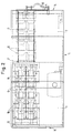
- Fig. 1 shows a side view, partly in broken view, of a sterilization system in the form of a container, which is generally designated 1.
- the container 1 is not arranged in a fixed place in the exemplary embodiment shown, but is transportable and can therefore, for. B. be placed on a truck or can even form a truck trailer itself.
- the plant for sterilizing infectious hospital waste is accommodated in this container 1.
- the system shown has an input end 14 which is closed by a pivotably arranged door 4.
- This door 4 can be opened and closed by an operator using a handle 16.
- two chambers are formed in the interior of the container, namely a first lock chamber 2 and a subsequent sterilization chamber 3.
- a preparation conveyor belt 5 is arranged within the lock chamber 2 and is dimensioned such that a plurality of plastic containers, for example five plastic containers, can be arranged one behind the other in the conveying direction of the belt. Furthermore, the preparation conveyor belt 5 is dimensioned so wide, for example, that two or more plastic containers 6 can be arranged side by side on the conveyor belt. In the embodiment shown, the preparation conveyor belt 5 runs obliquely upwards in the conveying direction, so that the entry end of the lock chamber 2 can be arranged lower than the discharge end.
- the lock chamber 2 can be hermetically sealed with the aid of a lock door 7 with respect to the sterilization chamber 3 and a mechanism (not shown) is provided which ensures that the lock door 7 always remains hermetically sealed as long as either the door 4 at the entry end 14 is open or the door 12 at the discharge end 15 Sterilization chamber 3 is open. This ensures that, for example, gases cannot enter the lock chamber 2 during the microwave treatment and vice versa.
- a device can also be provided, by means of which the discharge door 12 is kept closed after the garbage container 6 has been transferred from the preparation conveyor belt 5 to a main conveyor belt within the sterilization chamber 3 until the sterilization process has been completed.
- the lock chamber 2 is directly connected to the sterilization chamber 3 and after opening the lock door 7 the load on plastic containers 6, which is on the preparation conveyor belt 5, can be transferred to the main conveyor 8.
- the lock door 7, which can be designed, for example, as a sliding door, is hermetically sealed and likewise the discharge door 12 at the discharge end 15 of the sterilization chamber 3 is hermetically sealed. Then, with the aid of a mechanism, 10 injection needles are lowered from above the plastic container 6, so that the injection needles 17 pierce the plastic container arranged below them in the lid area. Water or a disinfectant can then be injected into the interior of the respective container via the injection needles 17.
- either hot steam can be introduced into the sterilization chamber 3 via a suitable device and an opening 11, so that a correspondingly high back pressure builds up inside the sterilization chamber 3.
- a suitable device and an opening 11 so that a correspondingly high back pressure builds up inside the sterilization chamber 3.
- several injection needles to the respective plastic container 6, i.e. the respective lid of a plastic container is pierced, for example, by two injection needles arranged at a short distance from one another, an injection needle being provided to introduce water or the disinfectant into the relevant container , while the other needle is used to aspirate gases within the respective plastic container and to sterilize them via a separate circuit (not shown).
- This circuit can be suitable filter devices such. B. activated carbon filter or the like, or it may contain sections at which the gas drawn off via the needle is heated to a high temperature, thereby achieving sterilization. The sterilized gas can then either be returned to the sterilization room 3 or otherwise destroyed or discharged into the atmosphere.
- the injection needles inserted into the respective plastic containers remain inserted until the entire sterilization process has been completed. This prevents disease germs from penetrating from the inside of the respective plastic container to the outside via the injection needles.
- the injection needles also serve to hold the respective plastic container 6 in position.
- the main conveyor belt 8 can be driven via a drive mechanism 13 in such a way that the containers move back and forth on the main conveyor belt 8 become. This back and forth movement is carried out by the injection needles 17 and the associated devices 10.
- the injection needles 17 are finally pulled out of the respective cover parts with the aid of suitable drive means 9 and the discharge end 15 is then opened via the door 12.
- the main conveyor belt 8 is then driven accordingly in order to discharge the treated plastic containers from the system.
- the containers 6 are plastic containers that are permeable to microwaves, but also disposable containers that are removed, for example, with the help of a pressurized waste container that compresses them with 30 tons of pressure while reducing the volume .
- the respective containers may also burst, since they now only contain sterile waste.
- the preparatory conveyor belt 5 is moved step by step during the loading process until a total of ten waste containers 6 are arranged on the preparatory conveyor belt 5. Then the entry end 14 is closed via the door 4 and the batch is transferred within the lock chamber 2 into the sterilization chamber 3 in the manner described.
- the present invention is not limited to the exemplary embodiment according to FIGS. 1 to 2.
- the present invention is obviously not limited to the number of ten waste containers that make up one batch.
- the plastic container can also be provided with an opening which is used to heat the contents of the plastic container allow pressurized gases to flow out to prevent the containers from bursting.
- a suitable filter e.g. B. an activated carbon filter can be used, which prevents germs and the like can get out of the plastic container.
- the plastic containers can also be formed from a material that is particularly expandable under the influence of heat. As a result, an overpressure which occurs when its contents are heated in the microwave field can be absorbed without the risk that the plastic containers will burst under the influence of this overpressure or could otherwise be destroyed.
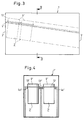
- Fig. 3 shows schematically a further embodiment or a side view of a sterilization tunnel, which is generally designated 1 '.
- the sterilization tunnel 1 ' has an entry end 3' and a discharge end 5 '.
- a roller conveyor 4 ' is arranged so that it slopes slightly downward from the entry end to the discharge end.
- a door (not shown) can be opened at the entry end 3 'and then the individual waste containers 2' with covers 6 'placed on them are placed on the roller conveyor tracks 4' such that the waste containers on side flanges 13 ' opposite sides are held supported by rollers.
- the downward inclination of the roller conveyor is dimensioned such that the respective garbage containers are conveyed 5 'due to their own weight in the direction of the discharge end, wherein they slide over the rollers of the roller conveyor 4'.
- the plastic container could be provided with a sack made of flexible material which, when the contents of the plastic container are heated in the microwave field, can protrude into the space outside the plastic container and can thus contribute to the reduction of excess pressure in the plastic container.
- Garbage containers roll towards the discharge end 5 'until they hit the previous garbage container, so that a continuous row of garbage containers is formed, between which there is no interruption or space, so that each garbage container is in an exact, position is always the same.
- water or a disinfectant is injected into each waste container with the aid of an injection device (not shown) which comprises injection needles which can be lowered from above towards the respective lid of a waste container.
- the injection needles can then either be withdrawn from the respective waste containers or kept in a pierced state, whereupon a microwave sterilization system (not shown) is activated. Due to the heating of the contents of the refuse containers occurring, gases and water vapor develop, so that an overpressure arises in each refuse container. This excess pressure can be measured, for example, with the aid of a pressure measuring device, which can expediently be integrated into the line system of the water supply.
- a temperature measuring device can be provided in order to measure the temperature occurring in each case inside the refuse container.
- the temperature measuring device comprises a temperature sensor, wherein according to an advantageous Embodiment of the invention, the injection needle itself can be designed as a temperature sensor or, according to an alternative embodiment, a displaceable temperature sensor can be arranged in the cavity of the injection needle, which can be moved out of the tip of the injection needle in order to measure the temperature inside the respective container.
- the inserted injection needles are then withdrawn again and the entire load of the sterilization tunnel can then be emptied by opening a corresponding door at the discharge end 5 '.
- a plurality of roller conveyor tracks can be provided running parallel to one another, for example two roller conveyor tracks, so that two garbage containers lying next to each other can be conveyed through the sterilization tunnel.
- FIG. 4 shows a sectional illustration along the line I-I in FIG. 3.
- roller conveyor tracks 4a ', 4b' and 4c ' are arranged parallel to each other. It can therefore be placed on the roller conveyor 4a 'and 4b' a left waste container 2 'and on the roller conveyor 4b' and 4c 'a right waste container, which are then conveyed in parallel through the sterilization tunnel 1'.
- the sterilization tunnel can expediently be installed on a chassis, for example on a truck or a truck trailer, the one shown Construction is particularly suitable for this, since it can be carried out in a comparatively short and compact design.
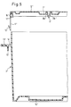
- Fig. 5 shows schematically a sectional view of the garbage container with a lid. 5
- a waste container is equipped at its upper end region with a circumferential flange 13 'which extends in the radial direction or horizontally.
- the circumferential flange slot-like openings 14 ' are formed at intervals, the locking tongues 11', 12 'of a cover 6' are assigned.
- the container 2 shown in Fig. 5 ' is filled with garbage, it is hermetically sealed with the help of the lid 6'.
- the cover 6 ' only needs to be placed over the upper edge of the container 2' and pressed firmly onto the upper edge.
- the locking tongues 11 ', 12' penetrate through the slot-shaped openings 14 'in the circumferential flange 13', penetrate these slot-shaped openings 14 'and finally reach an end position in which a hook-shaped projection 12' over one of the lower surface of the circumferential flange 13 'protruding wall-shaped projection 15' grab, whereby the lid is locked with the container 2 '.
- the cover 6 ' is also equipped with a circumferential groove 17', in the bottom region of which a seal 16 'is inserted, which consists of an elastic material such as rubber.
- this seal 16 ' is elastically deformed so that the hook-shaped projection 12' can slide over the wall-shaped projection 15 ', thereby causing the locking.
- the container is then tightly closed and in particular in a medium-tight manner.
- a recess 7' is also formed, in the central area of which there is a wall section according to a predetermined puncture point.
- This wall section consists of two wedge-shaped narrowing walls 8a 'and 8b', which form a wedge-shaped depression.
- the two wall sections merge into one another or are connected to one another in one piece.
- This lower common wall section tapers downward, as shown at 9 '.
- a kind of non-return valve is formed by the wall extension, which is thinned in its wall thickness, whereby the construction works as follows:
- the wall sections 8a 'and 8b' from a relatively soft, resilient material, which favors the closing of the puncture opening.
- the container 2 ' may also have a recess 10' in its bottom region, which can serve as an additional water reservoir.
- a recess 10' in its bottom region, which can serve as an additional water reservoir.
- the heating of the garbage inside the garbage container can be increased to a temperature of 150 ° C, but a temperature of 120 ° C is preferred.
- Both the lid 6 'and the container 2' can be made of polyethylene or polypropylene.
- Each waste container has a substantially square shape when you look at the container from above, so that the exact positioning of the respective container in the sterilization tunnel is completely unproblematic.
Landscapes
- Health & Medical Sciences (AREA)
- Animal Behavior & Ethology (AREA)
- Epidemiology (AREA)
- Life Sciences & Earth Sciences (AREA)
- General Health & Medical Sciences (AREA)
- Public Health (AREA)
- Veterinary Medicine (AREA)
- General Chemical & Material Sciences (AREA)
- Chemical Kinetics & Catalysis (AREA)
- Chemical & Material Sciences (AREA)
- Apparatus For Disinfection Or Sterilisation (AREA)
- Processing Of Solid Wastes (AREA)
- Accommodation For Nursing Or Treatment Tables (AREA)
Applications Claiming Priority (2)
| Application Number | Priority Date | Filing Date | Title |
|---|---|---|---|
| DE3924744 | 1989-07-26 | ||
| DE3924744A DE3924744C1 (nl) | 1989-07-26 | 1989-07-26 |
Publications (3)
| Publication Number | Publication Date |
|---|---|
| EP0410306A2 EP0410306A2 (de) | 1991-01-30 |
| EP0410306A3 EP0410306A3 (en) | 1992-03-25 |
| EP0410306B1 true EP0410306B1 (de) | 1995-01-11 |
Family
ID=6385894
Family Applications (1)
| Application Number | Title | Priority Date | Filing Date |
|---|---|---|---|
| EP90113871A Expired - Lifetime EP0410306B1 (de) | 1989-07-26 | 1990-07-19 | Verfahren und Vorrichtung zur Sterilisation von Müll, insbesondere Krankenhausmüll |
Country Status (9)
| Country | Link |
|---|---|
| US (1) | US5609830A (nl) |
| EP (1) | EP0410306B1 (nl) |
| JP (1) | JPH0397461A (nl) |
| AT (1) | ATE116861T1 (nl) |
| AU (1) | AU633944B2 (nl) |
| CA (1) | CA2021647A1 (nl) |
| DE (2) | DE3924744C1 (nl) |
| DK (1) | DK0410306T3 (nl) |
| ES (1) | ES2068289T3 (nl) |
Families Citing this family (23)
| Publication number | Priority date | Publication date | Assignee | Title |
|---|---|---|---|---|
| US5246674A (en) | 1990-10-25 | 1993-09-21 | Helmut Katschnig | Microwave apparatus, and container for use in a microwave apparatus |
| JPH04352959A (ja) * | 1991-05-29 | 1992-12-08 | Imusetsuku:Kk | 医療用廃棄物処理装置 |
| JPH0538489A (ja) * | 1991-08-07 | 1993-02-19 | Ink:Kk | 医療廃棄物処理方法及びその装置 |
| DE4128854C1 (en) * | 1991-08-30 | 1992-12-24 | Gabler Maschinenbau Gmbh, 2400 Luebeck, De | Sterilisation and comminution of infected medical waste - by charging waste in hermetically sealable container with crushing mechanism at bottom attached to steam chamber receiving waste |
| DE4129304A1 (de) * | 1991-09-03 | 1993-03-04 | Fuerst Zu Loewenstein Wertheim | Verfahren und vorrichtung zum desinfizieren oder sterilisieren von infektioesem abfall, wie krankenhausmuell |
| JPH08130B2 (ja) * | 1991-10-07 | 1996-01-10 | 川重防災工業株式会社 | 医療廃棄物の処理装置 |
| DE4234062A1 (de) * | 1992-10-09 | 1994-04-14 | Straehle Andreas | Vorrichtung zum Desinfizieren und/oder Sterilisieren von infektiösem Müll |
| GB9222777D0 (en) * | 1992-10-30 | 1992-12-09 | Narbonne Yves | Apparatus for handling biological fluid bags |
| KR960702357A (ko) * | 1993-05-11 | 1996-04-27 | 마이호페르 빌헬름 아우겐 | 오물 처리 장치 |
| DE4338710C2 (de) * | 1993-11-12 | 1997-07-24 | Dietmar Seifried | Verfahren und Vorrichtung zur Desinfektion von Abfällen |
| US5792421A (en) * | 1995-07-24 | 1998-08-11 | Microsterile Safe Corporation | Non-intrusive microwave decontamination of infectious waste |
| US6753517B2 (en) | 2001-01-31 | 2004-06-22 | Cem Corporation | Microwave-assisted chemical synthesis instrument with fixed tuning |
| FR2842111B1 (fr) * | 2002-07-10 | 2005-12-16 | Cedric Francis Beraud | Procede de decontamination de dechets et sac pour sa mise en oeuvre |
| ITBO20030402A1 (it) * | 2003-06-30 | 2005-01-01 | Luciano Salda | Macchina per il trattamento di prodotti con le microonde, particolarmente per la sterilizzazione dei rifiuti solidi ospedalieri usualmente raccolti in apposite scatole di cartone o di materia plastica ondulata e relativo metodo di funzionamento. |
| KR100928275B1 (ko) * | 2004-04-12 | 2009-11-24 | 자이단호진 기타큐슈산교가쿠쥬쓰스이신키코 | 마이크로파를 사용한 감압 건조 방법 및 그 장치 |
| JP4712667B2 (ja) * | 2006-10-13 | 2011-06-29 | ニッポウ興産株式会社 | 医療廃棄物の加熱滅菌処理方法 |
| DE102010018241A1 (de) * | 2010-04-23 | 2011-10-27 | Biomedis Laborservice Gmbh | Dampfsterilisationsvorrichtung und Verfahren zur Sterilisierung von kontaminiertem medizinischem und/oder biologischem Material |
| DE202012002668U1 (de) | 2012-03-17 | 2012-04-03 | Hermann Eser | Vorrichtung zur Desinfektion oder Sterilisation von Infektionsmüll |
| DE102013109089A1 (de) * | 2013-08-22 | 2015-02-26 | Krones Ag | Vorrichtung zur Behandlung von Behältern in einer Getränkeabfüllanlage |
| CN109647864A (zh) * | 2019-01-11 | 2019-04-19 | 南开大学 | 一种农村生活垃圾原位低温热处理装置及应用 |
| CN112057640B (zh) * | 2020-09-27 | 2021-12-10 | 陕西森凯组织工程与再生医学科技有限公司 | 一种干细胞培养基消毒器 |
| CN113800138B (zh) * | 2021-09-22 | 2023-02-24 | 南京一苇医药科技有限公司 | 一种药物废液收集暂存装置 |
| CN115219007A (zh) * | 2022-07-15 | 2022-10-21 | 江西升阳计算机系统有限公司 | 一种基于5g数据的智慧医疗废物称重对接系统及设备 |
Family Cites Families (11)
| Publication number | Priority date | Publication date | Assignee | Title |
|---|---|---|---|---|
| US3939287A (en) * | 1974-06-17 | 1976-02-17 | Spicecraft, Inc. | Sterilizing apparatus and process |
| SE400027B (sv) * | 1974-12-02 | 1978-03-13 | Electrolux Ab | Anordning vid en med overtryck arbetande autoklav |
| SE412989B (sv) * | 1975-05-20 | 1980-03-31 | Lundgren Ernst Harry | Forfarande och anordning for automatisk bakteriologisk rengoring och desinficering av foremal |
| DE2908086A1 (de) * | 1979-03-02 | 1980-09-11 | Helmut Goeldner | Verfahren und vorrichtung zum desinfizieren und sterilisieren von mit keimen behafteten gegenstaenden |
| DE3037038A1 (de) * | 1980-10-01 | 1982-05-06 | Theodor Lentjes | Eigensteifer behaelter mit einem deckel als wegwerf-aufnahmegefaess fuer sondermuell, insbesondere fuer medizinischen muell |
| DE3317300C2 (de) * | 1983-05-11 | 1986-11-20 | Vieregge-Bruns, Günther, 3070 Nienburg | Standfester, verschließbarer Behälter zur Aufnahme eines standfesten Innenbehälters mit Krankenhausabfall |
| DE3505571C2 (de) * | 1985-02-18 | 1991-03-07 | GVB SANIMED Hygiene- und Medizintechnik GmbH, 3070 Nienburg | Vorrichtung zur Desinfektion und Sterilisation von Matratzen mit Hilfe von Mikrowellen |
| DE3505570C1 (de) * | 1985-02-18 | 1991-01-24 | GVB SANIMED Hygiene- und Medizintechnik GmbH, 3070 Nienburg | Vorrichtung zur Behandlung von Infektionsmüll mit Hilfe von Mikrowellen |
| DE3710156A1 (de) * | 1987-03-27 | 1988-10-06 | Wolfgang Schinke | Vorrichtung zur behandlung von infektionsmuell mit hilfe von mikrowellen |
| DE3913472A1 (de) * | 1989-04-24 | 1990-10-25 | Pilema S R L | Verfahren zur sterilisation von medizinalabfaellen |
| JPH0330288A (ja) * | 1989-06-07 | 1991-02-08 | Wolfgang Moshammer | 含水物質などにマイクロ波エネルギーを放射して殺菌する方法と装置 |
-
1989
- 1989-07-26 DE DE3924744A patent/DE3924744C1/de not_active Expired - Fee Related
-
1990
- 1990-07-19 DK DK90113871.9T patent/DK0410306T3/da active
- 1990-07-19 DE DE59008228T patent/DE59008228D1/de not_active Expired - Fee Related
- 1990-07-19 EP EP90113871A patent/EP0410306B1/de not_active Expired - Lifetime
- 1990-07-19 ES ES90113871T patent/ES2068289T3/es not_active Expired - Lifetime
- 1990-07-19 AT AT90113871T patent/ATE116861T1/de not_active IP Right Cessation
- 1990-07-20 CA CA002021647A patent/CA2021647A1/en not_active Abandoned
- 1990-07-25 JP JP2197567A patent/JPH0397461A/ja active Pending
- 1990-07-26 AU AU59895/90A patent/AU633944B2/en not_active Ceased
-
1994
- 1994-02-28 US US08/202,600 patent/US5609830A/en not_active Expired - Fee Related
Also Published As
| Publication number | Publication date |
|---|---|
| ES2068289T3 (es) | 1995-04-16 |
| EP0410306A2 (de) | 1991-01-30 |
| AU633944B2 (en) | 1993-02-11 |
| DE59008228D1 (de) | 1995-02-23 |
| DE3924744C1 (nl) | 1991-02-07 |
| AU5989590A (en) | 1991-01-31 |
| DK0410306T3 (da) | 1995-03-27 |
| JPH0397461A (ja) | 1991-04-23 |
| ATE116861T1 (de) | 1995-01-15 |
| CA2021647A1 (en) | 1991-01-27 |
| US5609830A (en) | 1997-03-11 |
| EP0410306A3 (en) | 1992-03-25 |
Similar Documents
| Publication | Publication Date | Title |
|---|---|---|
| EP0410306B1 (de) | Verfahren und Vorrichtung zur Sterilisation von Müll, insbesondere Krankenhausmüll | |
| DE4227830C1 (de) | Verfahren und Einrichtung zum Desinfizieren eines Knochentransplantats, insbesondere eines humanen Spongiosa-Transplantats | |
| AT401471B (de) | Vorrichtung und verfahren zur behandlung von medizinischen sonderabfällen | |
| EP0287549B1 (de) | Vorrichtung zum Erhitzen von Gegenständen und Organismen | |
| AT407959B (de) | Mikrowellensterilisationseinrichtung | |
| DE3317300C2 (de) | Standfester, verschließbarer Behälter zur Aufnahme eines standfesten Innenbehälters mit Krankenhausabfall | |
| DE602004004128T2 (de) | Maschine und verfahren zur behandlung von produkten mit mikrowellen | |
| EP0483104A2 (de) | Anlage zum Erhitzen, Desinfizieren oder Sterilisieren von Gütern | |
| WO2006089603A1 (de) | Vorrichtung zum zuführen von in säcken angelieferten sterilen verschlüssen in eine abfüllanlage für flaschen oder dgl. | |
| EP0734734B1 (de) | Verfahren und Vorrichtung zur Desinfektion oder Sterilisation von Infektionsmüll | |
| DE69715945T2 (de) | Verfahren zum sterilen Verpacken eines Produktes | |
| DE3710156A1 (de) | Vorrichtung zur behandlung von infektionsmuell mit hilfe von mikrowellen | |
| DE3923841C2 (de) | Verfahren und Vorrichtung zum Keimfreimachen | |
| DE3627367C1 (de) | Vorrichtung zum Sterilisieren von Muell,insbesondere Infektionsmuell | |
| DE2439157A1 (de) | Verfahren und anordnung zum fuellen und verschliessen vorfabrizierter verpackungsbehaelter unter aseptischen bedingungen | |
| EP0372664B1 (de) | Dampfdrucksterilisator zum Sterilisieren von Abfällen oder dergleichen | |
| DE19833024C2 (de) | Verfahren und Vorrichtung zur Desinfektion oder Sterilisation von infizierten Materialien | |
| DE69901715T2 (de) | Verfahren zur externen dekontamination eines verpackten gegenstands | |
| CH680341A5 (nl) | ||
| DE4234062A1 (de) | Vorrichtung zum Desinfizieren und/oder Sterilisieren von infektiösem Müll | |
| DE4019620C2 (nl) | ||
| DE4235512C2 (de) | Verfahren und Kraftfahrzeug zum Desinfizieren von, insbesondere medizinischem oder dergleichen, Abfall | |
| DE3833281C1 (nl) | ||
| WO1994026433A1 (de) | Entsorgungsvorrichtung für abfälle | |
| DE69416877T2 (de) | Anlage zur mahlung und dekontaminierung von abfällen, insbesondere von krankenhausabfällen . |
Legal Events
| Date | Code | Title | Description |
|---|---|---|---|
| PUAI | Public reference made under article 153(3) epc to a published international application that has entered the european phase |
Free format text: ORIGINAL CODE: 0009012 |
|
| AK | Designated contracting states |
Kind code of ref document: A2 Designated state(s): AT BE CH DE DK ES FR GB GR IT LI NL SE |
|
| PUAL | Search report despatched |
Free format text: ORIGINAL CODE: 0009013 |
|
| AK | Designated contracting states |
Kind code of ref document: A3 Designated state(s): AT BE CH DE DK ES FR GB GR IT LI NL SE |
|
| 17P | Request for examination filed |
Effective date: 19920902 |
|
| 17Q | First examination report despatched |
Effective date: 19940517 |
|
| GRAA | (expected) grant |
Free format text: ORIGINAL CODE: 0009210 |
|
| ITF | It: translation for a ep patent filed | ||
| AK | Designated contracting states |
Kind code of ref document: B1 Designated state(s): AT BE CH DE DK ES FR GB GR IT LI NL SE |
|
| REF | Corresponds to: |
Ref document number: 116861 Country of ref document: AT Date of ref document: 19950115 Kind code of ref document: T |
|
| EAL | Se: european patent in force in sweden |
Ref document number: 90113871.9 |
|
| REF | Corresponds to: |
Ref document number: 59008228 Country of ref document: DE Date of ref document: 19950223 |
|
| ET | Fr: translation filed | ||
| GBT | Gb: translation of ep patent filed (gb section 77(6)(a)/1977) |
Effective date: 19950220 |
|
| REG | Reference to a national code |
Ref country code: DK Ref legal event code: T3 |
|
| REG | Reference to a national code |
Ref country code: GR Ref legal event code: FG4A Free format text: 3014699 |
|
| REG | Reference to a national code |
Ref country code: ES Ref legal event code: FG2A Ref document number: 2068289 Country of ref document: ES Kind code of ref document: T3 |
|
| PGFP | Annual fee paid to national office [announced via postgrant information from national office to epo] |
Ref country code: GB Payment date: 19950911 Year of fee payment: 6 |
|
| PGFP | Annual fee paid to national office [announced via postgrant information from national office to epo] |
Ref country code: FR Payment date: 19950918 Year of fee payment: 6 |
|
| PGFP | Annual fee paid to national office [announced via postgrant information from national office to epo] |
Ref country code: CH Payment date: 19950920 Year of fee payment: 6 |
|
| PGFP | Annual fee paid to national office [announced via postgrant information from national office to epo] |
Ref country code: AT Payment date: 19950921 Year of fee payment: 6 |
|
| PGFP | Annual fee paid to national office [announced via postgrant information from national office to epo] |
Ref country code: SE Payment date: 19950922 Year of fee payment: 6 Ref country code: NL Payment date: 19950922 Year of fee payment: 6 Ref country code: DK Payment date: 19950922 Year of fee payment: 6 |
|
| PGFP | Annual fee paid to national office [announced via postgrant information from national office to epo] |
Ref country code: GR Payment date: 19950929 Year of fee payment: 6 Ref country code: ES Payment date: 19950929 Year of fee payment: 6 |
|
| PGFP | Annual fee paid to national office [announced via postgrant information from national office to epo] |
Ref country code: BE Payment date: 19951009 Year of fee payment: 6 |
|
| PLBE | No opposition filed within time limit |
Free format text: ORIGINAL CODE: 0009261 |
|
| STAA | Information on the status of an ep patent application or granted ep patent |
Free format text: STATUS: NO OPPOSITION FILED WITHIN TIME LIMIT |
|
| 26N | No opposition filed | ||
| PG25 | Lapsed in a contracting state [announced via postgrant information from national office to epo] |
Ref country code: GB Effective date: 19960719 Ref country code: DK Effective date: 19960719 Ref country code: AT Effective date: 19960719 |
|
| REG | Reference to a national code |
Ref country code: DK Ref legal event code: EBP |
|
| PG25 | Lapsed in a contracting state [announced via postgrant information from national office to epo] |
Ref country code: SE Effective date: 19960720 Ref country code: ES Free format text: LAPSE BECAUSE OF EXPIRATION OF PROTECTION Effective date: 19960720 |
|
| PG25 | Lapsed in a contracting state [announced via postgrant information from national office to epo] |
Ref country code: LI Effective date: 19960731 Ref country code: CH Effective date: 19960731 Ref country code: BE Effective date: 19960731 |
|
| BERE | Be: lapsed |
Owner name: NORDPUNKT A.G. Effective date: 19960731 |
|
| PG25 | Lapsed in a contracting state [announced via postgrant information from national office to epo] |
Ref country code: GR Free format text: THE PATENT HAS BEEN ANNULLED BY A DECISION OF A NATIONAL AUTHORITY Effective date: 19970131 |
|
| PG25 | Lapsed in a contracting state [announced via postgrant information from national office to epo] |
Ref country code: NL Effective date: 19970201 |
|
| REG | Reference to a national code |
Ref country code: GR Ref legal event code: MM2A Free format text: 3014699 |
|
| GBPC | Gb: european patent ceased through non-payment of renewal fee |
Effective date: 19960719 |
|
| REG | Reference to a national code |
Ref country code: CH Ref legal event code: PL |
|
| PGFP | Annual fee paid to national office [announced via postgrant information from national office to epo] |
Ref country code: DE Payment date: 19970327 Year of fee payment: 7 |
|
| PG25 | Lapsed in a contracting state [announced via postgrant information from national office to epo] |
Ref country code: FR Effective date: 19970328 |
|
| NLV4 | Nl: lapsed or anulled due to non-payment of the annual fee |
Effective date: 19970201 |
|
| EUG | Se: european patent has lapsed |
Ref document number: 90113871.9 |
|
| REG | Reference to a national code |
Ref country code: FR Ref legal event code: ST |
|
| PG25 | Lapsed in a contracting state [announced via postgrant information from national office to epo] |
Ref country code: DE Free format text: LAPSE BECAUSE OF NON-PAYMENT OF DUE FEES Effective date: 19980401 |
|
| REG | Reference to a national code |
Ref country code: ES Ref legal event code: FD2A Effective date: 19990601 |
|
| PG25 | Lapsed in a contracting state [announced via postgrant information from national office to epo] |
Ref country code: IT Free format text: LAPSE BECAUSE OF NON-PAYMENT OF DUE FEES Effective date: 20050719 |