EP0408074B1 - Von einem Elektromotor angetriebenes Fahrzeug und Antriebseinheit dafür - Google Patents
Von einem Elektromotor angetriebenes Fahrzeug und Antriebseinheit dafür Download PDFInfo
- Publication number
- EP0408074B1 EP0408074B1 EP90113482A EP90113482A EP0408074B1 EP 0408074 B1 EP0408074 B1 EP 0408074B1 EP 90113482 A EP90113482 A EP 90113482A EP 90113482 A EP90113482 A EP 90113482A EP 0408074 B1 EP0408074 B1 EP 0408074B1
- Authority
- EP
- European Patent Office
- Prior art keywords
- motor
- vehicle according
- speed change
- transmission
- transmission case
- Prior art date
- Legal status (The legal status is an assumption and is not a legal conclusion. Google has not performed a legal analysis and makes no representation as to the accuracy of the status listed.)
- Expired - Lifetime
Links
- 230000005540 biological transmission Effects 0.000 claims description 95
- 230000008859 change Effects 0.000 claims description 58
- 238000001816 cooling Methods 0.000 claims description 38
- 238000004891 communication Methods 0.000 claims description 2
- 238000010586 diagram Methods 0.000 description 14
- 230000007246 mechanism Effects 0.000 description 13
- 230000003247 decreasing effect Effects 0.000 description 10
- 230000001133 acceleration Effects 0.000 description 9
- 239000000428 dust Substances 0.000 description 6
- 230000020169 heat generation Effects 0.000 description 6
- 238000000638 solvent extraction Methods 0.000 description 6
- 238000000034 method Methods 0.000 description 4
- 230000006866 deterioration Effects 0.000 description 3
- 230000000694 effects Effects 0.000 description 3
- 230000002093 peripheral effect Effects 0.000 description 3
- XEEYBQQBJWHFJM-UHFFFAOYSA-N Iron Chemical group [Fe] XEEYBQQBJWHFJM-UHFFFAOYSA-N 0.000 description 2
- 230000008901 benefit Effects 0.000 description 2
- 230000008878 coupling Effects 0.000 description 2
- 238000010168 coupling process Methods 0.000 description 2
- 238000005859 coupling reaction Methods 0.000 description 2
- 238000007599 discharging Methods 0.000 description 2
- 239000006185 dispersion Substances 0.000 description 2
- 230000005389 magnetism Effects 0.000 description 2
- 239000002184 metal Substances 0.000 description 2
- 229910052751 metal Inorganic materials 0.000 description 2
- 230000004044 response Effects 0.000 description 2
- 238000011144 upstream manufacturing Methods 0.000 description 2
- AAQFSZFQCXLMNT-ACMTZBLWSA-N (3s)-3-amino-4-[[(2s)-1-methoxy-1-oxo-3-phenylpropan-2-yl]amino]-4-oxobutanoic acid;hydrochloride Chemical compound Cl.OC(=O)C[C@H](N)C(=O)N[C@H](C(=O)OC)CC1=CC=CC=C1 AAQFSZFQCXLMNT-ACMTZBLWSA-N 0.000 description 1
- 239000003513 alkali Substances 0.000 description 1
- 239000002585 base Substances 0.000 description 1
- 238000007664 blowing Methods 0.000 description 1
- 229910052793 cadmium Inorganic materials 0.000 description 1
- 238000002485 combustion reaction Methods 0.000 description 1
- 230000005669 field effect Effects 0.000 description 1
- 238000010438 heat treatment Methods 0.000 description 1
- 239000000463 material Substances 0.000 description 1
- 229910052759 nickel Inorganic materials 0.000 description 1
- 229920003002 synthetic resin Polymers 0.000 description 1
- 239000000057 synthetic resin Substances 0.000 description 1
- XLYOFNOQVPJJNP-UHFFFAOYSA-N water Substances O XLYOFNOQVPJJNP-UHFFFAOYSA-N 0.000 description 1
Images


Classifications
-
- B—PERFORMING OPERATIONS; TRANSPORTING
- B62—LAND VEHICLES FOR TRAVELLING OTHERWISE THAN ON RAILS
- B62K—CYCLES; CYCLE FRAMES; CYCLE STEERING DEVICES; RIDER-OPERATED TERMINAL CONTROLS SPECIALLY ADAPTED FOR CYCLES; CYCLE AXLE SUSPENSIONS; CYCLE SIDE-CARS, FORECARS, OR THE LIKE
- B62K11/00—Motorcycles, engine-assisted cycles or motor scooters with one or two wheels
- B62K11/02—Frames
- B62K11/04—Frames characterised by the engine being between front and rear wheels
-
- B—PERFORMING OPERATIONS; TRANSPORTING
- B62—LAND VEHICLES FOR TRAVELLING OTHERWISE THAN ON RAILS
- B62M—RIDER PROPULSION OF WHEELED VEHICLES OR SLEDGES; POWERED PROPULSION OF SLEDGES OR SINGLE-TRACK CYCLES; TRANSMISSIONS SPECIALLY ADAPTED FOR SUCH VEHICLES
- B62M7/00—Motorcycles characterised by position of motor or engine
- B62M7/12—Motorcycles characterised by position of motor or engine with the engine beside or within the driven wheel
-
- F—MECHANICAL ENGINEERING; LIGHTING; HEATING; WEAPONS; BLASTING
- F16—ENGINEERING ELEMENTS AND UNITS; GENERAL MEASURES FOR PRODUCING AND MAINTAINING EFFECTIVE FUNCTIONING OF MACHINES OR INSTALLATIONS; THERMAL INSULATION IN GENERAL
- F16H—GEARING
- F16H55/00—Elements with teeth or friction surfaces for conveying motion; Worms, pulleys or sheaves for gearing mechanisms
- F16H55/32—Friction members
- F16H55/52—Pulleys or friction discs of adjustable construction
- F16H55/56—Pulleys or friction discs of adjustable construction of which the bearing parts are relatively axially adjustable
- F16H55/563—Pulleys or friction discs of adjustable construction of which the bearing parts are relatively axially adjustable actuated by centrifugal masses
-
- F—MECHANICAL ENGINEERING; LIGHTING; HEATING; WEAPONS; BLASTING
- F16—ENGINEERING ELEMENTS AND UNITS; GENERAL MEASURES FOR PRODUCING AND MAINTAINING EFFECTIVE FUNCTIONING OF MACHINES OR INSTALLATIONS; THERMAL INSULATION IN GENERAL
- F16H—GEARING
- F16H9/00—Gearings for conveying rotary motion with variable gear ratio, or for reversing rotary motion, by endless flexible members
- F16H9/02—Gearings for conveying rotary motion with variable gear ratio, or for reversing rotary motion, by endless flexible members without members having orbital motion
- F16H9/04—Gearings for conveying rotary motion with variable gear ratio, or for reversing rotary motion, by endless flexible members without members having orbital motion using belts, V-belts, or ropes
- F16H9/12—Gearings for conveying rotary motion with variable gear ratio, or for reversing rotary motion, by endless flexible members without members having orbital motion using belts, V-belts, or ropes engaging a pulley built-up out of relatively axially-adjustable parts in which the belt engages the opposite flanges of the pulley directly without interposed belt-supporting members
- F16H9/16—Gearings for conveying rotary motion with variable gear ratio, or for reversing rotary motion, by endless flexible members without members having orbital motion using belts, V-belts, or ropes engaging a pulley built-up out of relatively axially-adjustable parts in which the belt engages the opposite flanges of the pulley directly without interposed belt-supporting members using two pulleys, both built-up out of adjustable conical parts
- F16H9/18—Gearings for conveying rotary motion with variable gear ratio, or for reversing rotary motion, by endless flexible members without members having orbital motion using belts, V-belts, or ropes engaging a pulley built-up out of relatively axially-adjustable parts in which the belt engages the opposite flanges of the pulley directly without interposed belt-supporting members using two pulleys, both built-up out of adjustable conical parts only one flange of each pulley being adjustable
-
- B—PERFORMING OPERATIONS; TRANSPORTING
- B62—LAND VEHICLES FOR TRAVELLING OTHERWISE THAN ON RAILS
- B62K—CYCLES; CYCLE FRAMES; CYCLE STEERING DEVICES; RIDER-OPERATED TERMINAL CONTROLS SPECIALLY ADAPTED FOR CYCLES; CYCLE AXLE SUSPENSIONS; CYCLE SIDE-CARS, FORECARS, OR THE LIKE
- B62K2202/00—Motorised scooters
-
- B—PERFORMING OPERATIONS; TRANSPORTING
- B62—LAND VEHICLES FOR TRAVELLING OTHERWISE THAN ON RAILS
- B62K—CYCLES; CYCLE FRAMES; CYCLE STEERING DEVICES; RIDER-OPERATED TERMINAL CONTROLS SPECIALLY ADAPTED FOR CYCLES; CYCLE AXLE SUSPENSIONS; CYCLE SIDE-CARS, FORECARS, OR THE LIKE
- B62K2204/00—Adaptations for driving cycles by electric motor
-
- F—MECHANICAL ENGINEERING; LIGHTING; HEATING; WEAPONS; BLASTING
- F16—ENGINEERING ELEMENTS AND UNITS; GENERAL MEASURES FOR PRODUCING AND MAINTAINING EFFECTIVE FUNCTIONING OF MACHINES OR INSTALLATIONS; THERMAL INSULATION IN GENERAL
- F16H—GEARING
- F16H57/00—General details of gearing
- F16H57/04—Features relating to lubrication or cooling or heating
- F16H57/048—Type of gearings to be lubricated, cooled or heated
- F16H57/0487—Friction gearings
- F16H57/0489—Friction gearings with endless flexible members, e.g. belt CVTs
Definitions
- the invention relates to a vehicle which runs by transmitting the rotation of an electric battery-driven motor to a driving wheel through a stepless speed change transmission and an automatic starting clutch.
- a vehicle of this type is known from DE-A-2218730. In this vehicle the speed change transmission does not influence the motor efficiency.
- EP-A-0024373 discloses a vehicle driven by an internal combustion engine, in which a driving wheel is rotatably supported by a transmission case pivotally connected to the vehicle body to be able to oscillate; a belt-type stepless speed change transmission provided within the transmission case connects the driving wheel to the motor; said motor is enclosed by a motor housing provided at a side portion of said transmission case.
- a second object of the present invention is to provide a power unit employing the above-described driving structure.
- a third object of the present invention is to provide an effective cooling structure on the basis of a motor in said power unit.
- a fourth object of the present invention is to provide an advantageous wiring structure of the electric power supply cord of the motor.
- the vehicle as described in the beginning is characterized in that said stepless speed change transmission is operated in a revolution range of said motor which is higher than a revolution number corresponding to the maximum power of said motor to maintain the speed of the motor within a range preselected to be within a predetermined percentage of maximum motor efficiency.
- the approaching of maximum efficiency is a matter which is established voluntarily according to the applying with excluding the low efficient range which may become disadvantageous by producing either a maximum torque or a large current in case the motor is loaded.
- the transmission mechanism When the rotation of the motor is raised up and it reaches a predetermined rotational number approaching maximum efficiency of the motor, the transmission mechanism is connected to a driving shaft side, and the rotation of the motor side is transmitted to the driving wheel side through the transmission mechanism only within this range. Therefore, the motor load at low efficient condition is avoided, and since it becomes possible to run by utilizing only within the range of good efficiency of the motor which was relatively limited originally, the consuming electric power is reduced. Consequently, the discharging efficiency of the battery becomes high whereby the battery may keep long life and the cruising distance can be extended. And, since the heat generation quantity is also decreased, the deterioration of capacity can be prevented and durability is increased and at the same time, since it may be satisfied with components for small electric power, the motor can be made compact and light.
- the transmitting mechanism can be made to an automatic centrifugal force clutch or automatic speed change transmission.
- the speed change can be carried out in a state that the range of the predetermined rotational number approaching maximum efficiency of the motor by the automatic speed change transmission in response to the establishment of speed change condition, the motor is always kept to adjacency of maximum efficiency during the speed changing.
- the range between two ratios of maximum and minimum of automatic speed change transmission is established so as to change the speed with keeping a proper motor rotational number as it is which the motor becomes to a maximum efficiency in the time of 100% of duty factor, the motor can be operated always in a maximum efficient state within usual speed change range, and thereby above-described advantage becomes most remarkable state.
- driving wheel is rotatably mounted to a transmission case movably supported to a vehicle body, and simultaneously, belt type stepless speed change transmission which is an automatic speed change transmission provided within the transmission case connected with this driving wheel and a motor contained within a motor housing provided to a side of transmission case are connected, so that it can be constructed as a power unit for rotationally driving said driving wheel.
- belt type stepless speed change transmission which is an automatic speed change transmission provided within the transmission case connected with this driving wheel and a motor contained within a motor housing provided to a side of transmission case are connected, so that it can be constructed as a power unit for rotationally driving said driving wheel.
- the entire power unit is preferably contained within the recess formed at the external surface of the driving wheel, so that it can be made further lighter and slimmer, and at the same time, the external appearance can be made neat and smart.
- the motor housing and the transmission case can also be made integrally, in this case, since the number of parts can be decreased and simultaneously the stress can be dispersed to both sides, the strength is improved and simultaneously the heat dispersion becomes good whereby the cooling efficiency of the motor housing side increase s.Further, when electric power supply cord of motor is fixed to a cover side mounted from sideward of the motor housing, the assembling of the motor is easy.
- a communication port for communicating the interior of transmission case and the interior of motor housing of said power unit is provided, and at the same time, the motor and the belt type stepless speed change transmission can be cooled by a common cooling fan.
- entire apparatus can be made compact by making the cooling fan to be common.
- cooling fan can also be mounted either to the driving pulley of the belt type stepless speed change transmission or to the rotary shaft of the motor adjoining to the communicating port within the motor housing. Even if it is made as these, entire apparatus can be made compactly and at the same time, in case of latter, the heat within the motor housing can be discharged efficiently to the belt type stepless speed change transmission side.
- a duct of which one end being communicated with the interior of the motor housing is provided at opposite of the transmission and another end of this duct is made to be opened to the interior space of vehicle, so that cooling air for the forced air cooling may be fed from this duct to the interior of the motor housing. If it is made as these, the cooling can be executed by introducing a clean air containing less dust and moisture.
- the electric power supply wire cord of the motor is either arranged in the interior of said duct, or being directly drawn out of the motor housing to its exterior without passing through the transmission case. If it is made as these, interference with the belt type stepless speed change transmission side can be avoided, and the wiring becomes easy and at the same time, according to the former, it can be fixed without using any special component, besides, it is not smeared directly by mud or moisture.
- Figs. 1 to 14 show a first embodiment of the present invention, in which
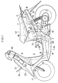
- Fig. 1 is a side view of entire body of an electric motor driving automatic bicycle mounted with a power unit according to the present invention, and its vehicle body frame is structured with front frame 2, central frame 3 and rear frame 4. Exterior side of the vehicle body frame is covered by a vehicle body frame made of synthetic resin assembled with leg shield 5, step floor 6, rear cover 7 and under cover 8.
- Direction steering handle 10 is provided at the top of head pipe 9 fixed to the front frame 2, and simultaneously a front fork 12 for supporting a front wheel 11 is connected to the bottom end.
- Front end of swing type power unit 1 for supporting the rear wheel 13 at the rear end is mounted to the rear portion of the central frame 3 by a pivot 14 whereby being supported to be able to oscillate freely to up and downward, and top surface of rear portion of the power unit 1 and the rear frame 4 are connected through a rear cushion 15.
- a stand 16 provided to the central frame 3 covers the bottom surface of front portion of the power unit 1 at a storing position of not shown, and serving concurrently as protection member for the motor to be described hereinafter stored within the interior.
- a container 19 for receiving a helmet etc. is provided to the inner side of the rear cover 7 at between the power unit 1 and the seat 17. This container 18 is formed of a material for shielding a magnetism so as any content such as floppy disk is not affected by the magnetism generated by the driving motor.
- a battery box 20 for storing a battery as an electric power supply for the motor driving to be described hereinafter is provided at the inner side of the under cover 8 in the central frame 3.
- a controller 21 for controlling the motor for driving and a charger 22 for charging the battery are provided to the inner side of the front cover 23 at the frontward of the head pipe 9, and electric wire cord 24 for charging to be connected to these is made to be able to connect to a commercially available electric power supply of exterior by opening a lid of not shown of the front cover 23.
- controller 21 and the charger 22 are possible to be accommodated to the various places with an integral body or separate body, for instance, the controller 21 can be provided to a place of A or B shown by imaginary line at the rear portion of vehicle body, and the charger 22 can also be provided to a place of C of vehicle body rear portion or D position of central portion of vehicle body. In case of D position, a lid 25 capable of opening and closing freely is provided to a portion of the stepping floor 6, and said charging cord 24 is made to be able to make out and in from here.
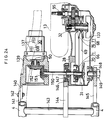
- the power unit 1 is provided with an unit case 26 for supporting the pivot 14 at the front end.
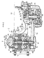
- the unit case 26 is an article that the motor housing 27 of front portion, the transmission case 28 of central portion and the gear box 29 of rear portion are integrally formed; and the motor 30 is contained within the motor housing 27, the belt type stepless speed change transmission 31 within the transmission case 28, and final reducing gear 32 within the gear box 29; and the motor 30 and the final reducing gear 32 are connected through the belt type stepless speed change transmission 31.
- the belt type stepless speed change transmission 31 is an example of transmission mechanism and automatic speed change apparatus in this application.
- the motor housing 27 is opened to the right side in a direction of vehicle width, and a tubular portion 34 of stator housing 33 of substantially cylindrical shape with bottom is inserted to said opening portion, whereby being blocked by the bottom portion 35.
- the stator housing 33 is a member for covering the right side opening portion of the motor housing 27, and a boss 36 protruding to inward (central side of vehicle body, it is same hereinafter) to its central portion at its bottom portion 35 and vent 37 of its surroundings are formed and simultaneously, the external peripheral portion is fixed to the motor housing 27 by bolt 38.
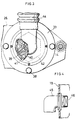
- a driver 39 protruding to sideward in rectangular tubular shape with surrounding the vent 37 is formed to outward of the bottom portion 35.
- the driver 39 is, as shown in Fig.
- a member of substantially hexagonal shape provided with driving circuit which will be described hereinafter, a plurality of V-shaped cooling fins 40 are provided to the internal surfaces of its each latus, and simultaneously FET (field effect transistor) 41 which will be described hereinafter is fixed to its external surface.
- FET field effect transistor
- a cup-shaped cover 42 contained with driver 39 is fixed to outward of the bottom portion 35, and the interior space is made to serve as an air introducing chamber 43.
- An end portion of flexible duct 44 is connected to the cover 42 (Figs. 1, 2 and 8), and another end portion is communicated to the interior of the container 19 provided to the bottom portion of the seat 17, and a sponge filter 46 for eliminating the dust within air is contained to the inlet opening of joint 45 for connecting its duct 44 to the container 19 (Fig. 4).
- the electric power supplying wire cord 47 for connecting the motor 30 and the driver 39 is led by piercing through the interior of the duct 44, which is wired through the cover 42 to the interior of the air introducing chamber 43 and the motor housing 27.
- a partitioning wall 48 is integrally formed to the boundary portion of the motor housing 27 and the transmission case 28, and each interior space of the motor housing 27 and the transmission case 28 formed by the partitioning wall 48 are communicated together.
- a rotary shaft 50 of the motor 30 is supported by bearings (51 and 52) provided to the partitioning wall 48 and a boss 36 of the stator housing 33, and an end of the rotary shaft 50 is protruded to the interior of the transmission case 28 by piercing through the partitioning wall 48.
- a rotary shaft portion cooling fan 53 for blowing to the vent 49 at a portion approaching to the partitioning wall 48 is provided to the rotary shaft 50 of the motor 30.
- the motor 30 is DC brushless motor, which is provided with a rotor 58 arranged with permanent magnet 57 around the external circumference of iron core 56 fixed to the rotary shaft 50 and a stator 62 made of stator coil 61 wound around iron core 60 fixed to the tubular portion 34 of the stator housing 33 by bolt 59. And, a magnet 63 fixed to an end portion of the rotary shaft 50 and a rotor position sensor 65 made of three hole elements 64 arranged to the boss 36 side by surrounding this magnet 63 are provided.
- stator 62 is previously assembled into the stator housing 33, and then this stator housing 33 is inserted from the opening portion into the interior of the motor housing 27, so that the motor case is constructed.
- the belt type stepless speed change transmission 31 is provided with a driving pulley 66 mounted to the rotary shaft 50 protruded from the motor housing 27 side into the interior of transmission case 28 and a driven pulley 68 mounted to an input shaft 67 of reducing gear 32 supported to the rear portion of transmission case 28, and an endless belt 69 is wound between said pulleys 66, 68.
- the driving pulley 66 is consisted of a fixed face 70 fixed to the rotary shaft 50 and a movable face 71 slidably supported in axial direction to this rotary shaft 50, and a centrifugal force weight 73 movably mounted in radial direction is arranged between this movable face 71 and a ramp plate 72 fixed to the rotary shaft 50.
- a pulley portion cooling fan 74 is integrally formed to the side surface of the fixed face 70.
- the pulley portion cooling fan 74 serves mainly the heat discharge of vicinity of fixed face 70, and it is provided as a subsidiary cooling fan relative to the rotary shaft portion cooling fan 53. Further, the fins may be cut out or made smaller in order to make lighter, in this case, dimension of width direction of the cover 54 can be made smaller.
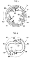
- the driven pulley 68 is consisted of a fixed face 76 supported to a sleeve 75 rotatably inserted relatively around the input shaft 67 of reducing gear 32 and a movable face 77 slidable in axial direction, and the driving power transmitted to this driven pulley 68 is transmitted to the input shaft 67 of reducing gear through a first centrifugal force clutch 78 which is a starting clutch.
- First centrifugal force clutch 78 is an example of a transmission mechanism and automatic centrifugal force clutch in this application. As will be apparent from Fig. 5, it is constructed with a clutch outer 79 fixed to an end portion of the input shaft 67 of reducing gear, a clutch inner 80 fixed to an end portion of sleeve 75, and three arms 81 whose one end is fixed to the side surface of the clutch inner 80, and each arms 81 are connected by coil spring 82 each other and at the same time, a pad 83 capable of coupling with friction to the clutch outer 79 is provided to the external peripheral portion. Further, a set spring 84 is mounted between the clutch inner 80 and mobile face 77. And, the clutch outer 79 and the clutch inner 80 are used in combination with the clutch inner and clutch outer of the second centrifugal force clutch 85.
- the second centrifugal force clutch 85 is for the engine brake, as will be described in detail in Fig. 6, in which respective weight 87 is fixed to the other end side of two bent arms 86 whose one end is mounted to the side surface of the clutch outer 79 and interval between both parties are connected by coil spring 88 and simultaneously a pad 89 capable of coupling with friction to the clutch inner 80 is provided thereof.
- the first centrifugal force clutch 78 connects the sleeve 75 and the input shaft 67 of reducing gear at, for example, over and established rotational number of little less than maximum efficiency producing rotational number of the motor 30, and the second centrifugal force clutch 85 is established so as to be further less, for example, about 400 rpm than the established rotational number of the first centrifugal force clutch 78.
- Final reducing gear 32 is supported through the ball bearings in which the input shaft 67 of reducing gear and intermediate shaft 90 are respectively provided to the transmission case 28 and the reducing gear cover 91 and the rotation of input gear 92 of the input shaft 67 of reducing gear is transmitted through two intermediate gears 93, 94 of the intermediate shaft 90 to an output gear 96 of vehicle shaft 95.
- Fig. 7 is a circuit diagram for showing a control system of the motor 30, in which a potential of potentiometer 101 connected to an accelerator grip 100 of direction steering handle 10 so as to control the rotational speed of the motor 30 and phase signal of the rotor 58 detected by the rotor position sensor 85 are inputted to the controller 21, and further, potentiometer 101, switch 102 for detecting a minimum operational angle of the acceleration grip 100, brake switch 103, vehicle speed sensor which is not shown and driving circuit 104 are connected to the controller 21.
- the controller 21 has a microcomputer, which determines a duty factor of current for conducting to the motor 30 according to the output signal of potentiometer 101 and the vehicle speed sensor, and determining the phase of alternating magnetic field in the stator coil 61 according to the output signal of the rotor position sensor 65, and outputting a PWM signal representing the phase and duty factor for each stator coil 61 to a driving circuit 104, and further discriminating the control state according to the output of the switch 102 and the brake switch 103 whereby outputting a control command signal to the driving circuit 104 in the time of braking.
- the driving circuit 104 includes a gate driving circuit 105 and switch circuit 106, and the gate driving circuit 105 is connected to the controller 21, and the switch circuit 106 to the stator coil 61, the switch circuit 106 is arranged such that three pairs of FETs 41 wired in series are connected in parallel between a battery 107 and ground GND, and the gate of each FET 41 is connected to the gate driving circuit 105, and further respective source-drain connection nodes are connected respectively with three terminals of the stator coil 61 which being star-wired respectively.
- This driving circuit 104 drives the FET 41 to be ON-OFF according to the PWM signal outputted by the controller 21 whereby conducting the current for generating the alternating magnetic field to the stator coil 61 of the motor 30, and the controller 21 conducts the terminal to the stator coil 61 by the FET 41 which outputs the control command signal whereby executing the electrical control by the motor 30.
- a torsional spring 111 for urging an acceleration grip 100 toward the idling position is mounted between a fixed bracket 109 of ring shape fixed to the middle of a handle pipe 108 and a rotary bracket 110 of tubular shape which is rotatably mounted on the front end of the handle pipe 108, and on the external circumference of which is mounted integrally by pressure the acceleration grip 100.
- the potentiometer 101 for operating by the rotational operation of the acceleration grip 100 includes a resistor 114 and a conductive body 113 printed in parallel to the surface of arc-shaped printed board 112 fixed to the bottom of the fixed bracket 109, and potentials of 0 volt and 5 volt are applied to this conductive body 113 and resistor 114 respectively.
- a guide plate 116 having an arc-shaped guide groove 115 is fixed in parallel with the printed board 112 at the interior of the fixed bracket 109, and a protrusion 118 formed to the rear surface of the guide groove 115 of the guide plate 116 is held to the rotary bracket 110 by passing through the guide groove 115 of the guide plate 116.
- a metal plate 119 connected electrically to the controller 21 is fixed to the front surface of sliding member 117 so as to be contacted simultaneously to the resistor 114 and the conductive body 113 of the printed board 112.
- the potentional of the metal plate 119 becomes about 0,5 volt in case when the acceleration grip 100 is positioned at the shown idling position, and when the acceleration grip 100 is rotated in arrow direction toward the full load position, its potential is increased gradually up to about 4,5 volt in case of this embodiment.
- Fig. 11 is a modelling graph for illustrating an establishing method of speed changing condition, wherein a motor characteristic of the motor 30 is shown by (I), and speed change characteristic of the belt type stepless speed change transmission 31 is shown by (II).
- this range W (shown to (II) side) is corresponded to a vicinity of maximum efficiency in this embodiment.
- the rotational number of the motor within this range is about from 3500 to 5800 rpm.
- the belt type stepless speed change transmission 31 is established with a condition so as to be speed-changed only when it is operated within the range of over 80 % in efficiency included with maximum efficiency ⁇ max of motor 30. That is, the diagram (II) takes vehicle speed in km/h abscissa, and rotational number in rpm of motor 30 and torque of rear wheel driving shaft in kg.cm on ordinates, and surrounding by hatched lines the range of rotational number of motor corresponding to the range of over 80 % in efficiency.
- the speed change curve may become within this range, and the clutch meets - what means that it is not the actual clutch means but is the operation starting point (timing) of the stepless belt transmission - at a point P1 which is a little lower rotational number than the maximum efficiency ( ⁇ max), producing rotational number No (4500 rpm) to be obtained with maximum efficiency whereby both the speed and the rotational number of the motor 30 are raised along the low ratio, and thereby the speed change is started with the constant rotational number from a point P2 of maximum efficiency producing the rotational number No.
- This speed change is increased in speed with stepless manner by maximum efficiency ( ⁇ max) producing the rotational number No per se whereby being executed up to the point P3 crossing with the top ratio. Thereafter the rotational number of the motor 30 and the vehicle speed are raised together along the top ratio and then it reaches a limiting point P4 of 80 % in efficiency.
- the speed at this point P4 is established as a limiting speed (for example 60 km/h).
- a limiting speed for example 60 km/h.
- the duty factor is taken as 100 %, in case when a running resistance is considered, as will be described hereinafter, the duty factor within the usual range can be established a little lower.
- Fig. 13 shows a supporting structure of the battery box 20 wherein the battery box 20 is supported on a supporting plate 120 fixed to the central frame 3 by protruding toward the right and left direction, and a battery 107 is contained within its interior to the right and left by interposing the central frame 3.
- the battery 107 supplies an electric power to the motor 30 according to the control of the controller 21.
- This electric motor 30 driving automatic bicycle is constructed such that the motor 30 is connected to the rear wheel 13 via the belt-type stepless speed change transmission 31, first centrifugal force clutch 78, second centrifugal force clutch 85 and final reducing gear 32, and the current of duty factor corresponding to the vehicle speed and the handling angle of the acceleration grip 100 is conducted, whereby running by the driving power of the motor 30.
- the effective radius of the driving pulley 66 is increased and at the same time the movable face 77 of the driven pulley 68 is driven in a direction of leaving away from the fixed face 76 through the endless belt 69, whereby its effective radius is decreased.
- Fig. 14 is a graph for showing the running capacity, the vehicle speed in km/h is taken on abscissa, and the rear wheel output in W, and the rotational number in rpm of the motor 30 or the engine is taken on the ordinates, and then the capacities of comparing examples 1 and 2 are noted in combination.
- the article of this embodiment in case of comparing with the comparing examples 1 and 2, is obtained with lower rotation and higher output. Therefore, the torque and current required to the rotation of the motor 30 becomes relatively lower, and the duty of the motor 30 becomes relatively less, and thereby the consuming electric power quantity and heat generating quantity suppressed.
- the discharging efficiency of the battery 107 is increased and being made to long life and simultaneously the component such as the motor 30 can be set corresponding to the small current and low heat generation quantity, it can be made to be light weight and miniaturization. Further, in the usual range, the rotational number of the motor 30 and the rear wheel output can be maintained within extremely wide range and substantially in constant, without appearing a mountain or valley as comparing example, broad flat torque characteristic can be realized, and thereby smooth running can be obtained.
- the motor characteristic by the duty factor corresponding to the diagram (I) becomes as shown in Fig. 12 when the duty factor of the motor in the usal range is previously set to, e.g. 6o % , by increasing the duty factor so as to tie up in turn each peak of efficiency curve by the duty factor from the point P3, the output increase for directing toward the point P4 is ensured, and it is possible to overcome the increase of the running resistance.
- the setting of the usual range duty factor in this case to be 60 % enables to ensure 40 % as duty factor of excessive amount against the running resistance, and smoother and powerful running becomes possible.
- the second centrifugal force clutch 85 is connected when the rotational number of the input shaft 87 of the reducing gear reaches over the established rotational number less than the established rotational number of the first centrifugal force clutch 78 at a state that power is transmitted from the rear wheel 13 to the belt-type stepless speed change transmission 31.
- the second centrifugal force clutch 85 is connected whereby the torque produced to the rear wheel 13 is transmitted to the motor 30, therefore, the motor 30 can be used as a load. Further, the established rotational number of the second centrifugal force clutch 85 is less than the established rotational number of the first centrifugal force clutch 78, and since the second centrifugal force clutch 85 maintains the connected condition even after the first centrifugal force clutch 78 is left away in the time of speed reducing, speed reducing can be smoothly executed whereby good running feeling can be obtained. Particularly, in this embodiment, since electric braking is carried out by the motor 30 even in the time of braking, a better braking characteristic can be obtained.
- the air that has cooled the driver 39 cools the rotor position sensor 65, and then flowing from the vent 37 of the stator housing 33 into its interior and cooling the stator coil 61 of the heat-generated motor 30, whereby a deterioration of the capacity according to the heat generation of the motor 30 can be prevented. Thereafter, flowing from the vent 49 formed to the partitioning wall 48 into the interior of the transmission case 28, while cooling the belt-type stepless speed change transmission 31 as well as the pulley portion cooling fan 74, and being discharged from the discharge outlet 55 to the exterior.
- the cooling mechanism can be simplified. And, since this cooling air can cool the driver 39, it is not necessary to provide exclusive cooling mechanism and it is advantageous. Further, since the rotor position sensor 65 which dislikes dust is provided upstream side cooling air, adhering of dust can extremely be prevented. In this case, since the filter 46 is provided, it becomes further clear. In addition, since the inlet of the duct 44 is opened to the space of the interior of the vehicle body, clean air of less dust and moisture can be introduced.
- the duct 44 is connected to the interior of the container 19, this duct 44 can be connected to the suitable place of the frame pipe.
- the motor 30 since the motor 30 is located upstream of the cooling air, the motor 30 can avoid the heating effect from the belt-type stepless speed change transmission 31 side.
- the power unit 1 when the first cooling fan 53 is made coaxially with the rotary shaft 50, the power unit 1 can be made to be small size and light weight.
- the discharge outlet 55 is provided at the rear end portion of the transmission case 28, the entire transmission mechanism can be cooled.
- this embodiment includes many advantages other than above described. Firstly, since the motor housing 27 and the transmission case 28 are made integrally, the number of parts can be decreased and at the same time, since the stress can be dispersed to both sides, strength is increased and simultaneously heat dispersion becomes good whereby the cooling efficiency of the motor housing 27 side is increased.
- stator 62 of the motor 30 can be assembled into the interior of the motor housing 27 by inserting from its opening portion, work is easy, and particularly, according to this embodiment, since it is previously fixed to the stator housing 33 and this is inserted from the opening portion of the motor housing 27, its assembling is further easier.
- the rotary shaft 50 of the motor 30 serves concurrently as the input shaft of the belt-type stepless speed change transmission 31, axial directional dimension of the power unit 1 can be reduced. Further, since the electric power supply wire cord 47 for connection with the motor 30 and the driver 39 is pierced through the interior of the duct 44, mud and moisture and the like splashed to the electric power supply cord 47 can be made so as not to be directly disturbed even without using other particular member. Further, when the power supply cord 47 is previously passed through the cover 42 side, the cover 42 can be fixed at the wired state, whereby assembling efficiency is increased. In this case, it is not necessarily required to passing through the cover 42 or its similar functional parts. And, since the electric power supply cord 47 is directly drawn out of the motor housing 27 of the opposite side of the belt-type stepless speed change transmission 31 to the exterior , it can be passed to such place that does not interfere with the belt-type stepless speed change transmission 31.
- Fig. 15 is second embodiment that first centrifugal force clutch 78 and second centrifugal force clutch 85 are provided to the driving pulley 66 side, and only the parts corresponding to the belt-type stepless speed change transmission 31 of Fig. 2 are shown.
- both clutches are contained to the rear surface of the fixed face 70 of the driving pulley 66. That is, the first centrifugal force clutch 78 utilizes the fixed face 70 as a clutch outer, and an arm 81 fixed to the base portion side of the fixed face 70 is made to be able to slide with the internal surface of the external circumferential flange 123 of the clutch inner 122 fixed to the rotary shaft 50.
- the second centrifugal force clutch 85 utilizes the internal peripheral wall 70a of the fixed face 70 that a pad 89 of a bent arm 86 fixed to the clutch inner 122 extended in parallel with the rotary shaft 50 of the motor as a clutch outer and thereby it is made slidable to this.
- the driving pulley 66 can be effectively utilized, and reducing of the number of parts and making to be compact become possible.
- both of these clutches can be provided to the movable face 71 side of the driving pulley 66, and also it can be provided to the movable face 77 of the driven pulley 68 (refer to Fig. 19).
- Figures 16 and 17 show the third embodiment utilizing a brush-type motor.
- the motor housing 27 is separately contructed from the transmission case 28, and being fixed by bolt 124.
- the stator 62 of the motor 30 is fixed to the internal surface of the motor housing 27, and the commutator 125 is contacted with the brush 127 provided to the side portion of the motor housing 27 at between the rotor 58 and the wall 126 connected to the transmission case 28 of the motor housing 27.
- Electric power supply cord 128 of the brush 127 is extended to the exterior of the transmission case 28 by piercing through the wall portion of the motor housing 27.
- a vent 37 is provided to the cover 129 for covering the right side opening portion of the motor housing 27, and an air cleaner 130 is provided to its right side.
- a suction inlet 131 for communicating to the outside air is formed to the wall surface of the air cleaner 130, and filter element 132 is contained to the inside of this portion.
- the interior of the air cleaner 130 is communicated with the interior of the motor housing 27 through the vent 37.
- another vent 49 is also provided to the wall 126, and another more vent 49a accorded with this is formed to the transmision case 28 side superposing with the wall 126.
- a transmission mechanism according to this application and automatic centrifugal force clutch 133 which is an example of automatic centrifugal force clutch are provided to the driven pulley 68 side of the belt-type stepless speed change transmision 31 connected to the rotary shaft 50 of the motor 30.
- forced cooling for the parts of the motor 30 and the belt-type stepless speed change transmission 31 of the transmission case 28 is simultaneously carried out by the single pulley portion cooling fan 74.
- Fig. 17 shows a motor characteristic of this embodiment, rotational number in rpm of the motor 30 is taken on abscissa, and efficiency in %, output in W, current in A and torque in kg ⁇ m are taken on ordinates.
- maximum efficiency ⁇ max is obtained in case when the rotational number of motor 30 is about 3700 rpm and efficiency is sufficiently increased as it is approximately over 50 % at 2000-4500 rpm, the efficiency corresponding to this rotational number is the vicinity of maximum efficiency according to this embodiment.
- the duct portion for the cooling air can be made in short and the brush 127 is located at opposite side of the air cleaner 130 by interposing the motor 30, effect of the brush 127 causing from dust and moisture sucked in together with air can be decreased. Furthermore, since the electric power supply cord 128 is drawn out of side portion of the motor housing 27 to the exterior thereof, even though it is made as these, they do not interfere with the belt-type stepless speed change transmission 31.
- Figures 18 to 22 show the fourth embodiment.
- Fig. 18 shows a side view of the electric motor driving automatic bicycle according to this embodiment
- Figs 19 shows a cross sectional view of said power unit
- the front frame 2 and central frame 3 are channel-shaped.
- the power unit 1 is pivotally fixed to a plate-shaped connecting member 134 extended long to rearward from the central frame 3, and being contained within recess 135 of convex to vehicle center side formed to the sideward of the rear wheel 13.
- the motor 30 is arranged higher than the wheel shaft 95.
- a controller 21 is contained within small container 19 formed to downward of seat 17.
- Interior structure of the power unit 1 has a similar basic structure approximately as previous embodiment as shown in Fig. 18, but it is constituted in such a manner that air cleaner is deleted, and final reducing gear 32 is simplified, and input gear 92 formed to the input shaft 67 of reducing gear 32 and output gear 96 on the wheel shaft 95 are directly meshed each other.
- Automatic centrifugal force clutch 133 is arranged to vehicle body center side to the rear surface of movable face 77 forming the driven pulley 68.
- Pulley portion cooling fan 74 is arranged coaxially with the rotary shaft 90 separately to the driving pulley 66.
- the power unit 1 assembled with the motor 30 is miniaturized whereby being contained within the recess of side surface of the rear wheel 13, entire unit is made further lighter and slimmer at the same time external appearance becomes neat and smart. Further, since the motor 30 is disposed higher than the wheel shaft 95, mud and water become difficult to enter the motor 30.
- battery 107 is contained within the central frame 3. According to this, assembling and disassembling of the battery 107 become easy. Further, the battery 107 is effectively protected by the central frame 3. This is same in the front frame 2 side.
- the battery 107 is connected in parallel with the controller 21 and the motor 30 at the same time, the battery 107 itself is structured to use a plurality of individual batteries 1071--- 107 N by sequential switching manner.
- This plurality of batteries 1071--- 107 N are connected in parallel, and remaining capacity indicator of the battery is constructed by the shifting switches SW1 --- SW N , and lamps L1 --- L N .
- each lamp L1 --- L N is all lighted brightly.
- the switch SW1 is firstly turned ON and the motor 30 is driven, the lamp L1 is brightly lighted in the beginning, but soon the discharge capacity of the individual battery 1071 is dropped down by the load of motor 30 whereby the voltage is dropped down.
- this lamp L1 condition means the indication in short of remaining discharge capacity of the battery 1071, a rider may turn ON, for example, the switch SW2 for switching to the battery 1072.
- the indication based on the lighting condition of lamp they can be used by switching to one that has a discharge capacity in turn one by one to next new one.
- the usual remaining capacity indication of battery used conventionally is indicated by the voltage drop of the battery, since the voltage varies by temperature, there is a case of using a temperature compensation circuit and the like so as to obtain a correct indication. And, in case of alkali battery (Ni - Cd, Ni - Zn) and the like, since the quantity of voltage drop is small, and having a characteristic that the voltage is not greatly dropped until the discharge capacity becomes over 90%, there may be difficulty to confirm the remaining capacity. In this point, according to this embodiment, since the remaining capacity corresponding to the using number of battery can be recognized, that of simple in structure and correct remaining capacity indication can be expected.
- Figs. 23 and 24 show the fifth embodiment that the motor and the transmission mechanism are separately constructed.
- Fig. 23 shows a side view of right side of rear portion of vehicle body, wherein the motor 30 is connected to the bracket 138 provided by protruding rearwardly the side portion bracket 137 to the rear frame 4, and at the same time, a supporting plate 140 extended to frontward of box 139 meshed with one end of the motor 30 is connected to a bracket 141 extended from the rear frame 4 to rearward by bolt 142 whereby being fixed to the rear frame 4 side.
- Fig. 24 is a diagram for showing a transmission mechanism portion by sectional view, wherein rear frame 4 is provided so as to make pair to right and left, and both sides of front end portion of the transmission case 28 are rotatably supported to each rear end portions of supporting arms 144, 145 extended to rearward respectively from middle portion of cross pipe 143 connected between said both parts and the rear frame 4 of left side.
- Belt type stepless speed change transmission 31 similar to the third embodiment, final reducing gear 32 and automatic centrifugal force clutch 133 are provided within the transmission case 28.
- Connection of the transmission case 28 and the supporting arm 144 is made by engaging a boss portion 147 formed to the right side of the transmission case 28 to a bearing 146 provided to the rear end portion of supporting arm 144.
- Input shaft 150 of the transmission of the belt type stepless speed change transmission 31 is arranged in parallel with cross pipe 143 on same axis of pivot bolt 149, and the driving pulley 66 is supported to an end, and other end is entered the interior of gear box 139, whereby being connected with bevel gear 151, and at the same time, being rotatably supported by ball bearing provided at wall of gear box 139 and boss portion 147 of transmission case 28.
- Bevel gear 151 is meshed with bevel gear 152 mounted to an end of rotary shaft 50 of the motor 30.
- each supporting method with respect to the motor 30 and the rear frame 4 of the transmission case 28 is not limited to this embodiment but various methods are possible.
- the power unit 1 is not limited to the automatic bicycle but it can be applied for other vehicle such as automatic tricycle.
Landscapes
- Engineering & Computer Science (AREA)
- General Engineering & Computer Science (AREA)
- Mechanical Engineering (AREA)
- Chemical & Material Sciences (AREA)
- Combustion & Propulsion (AREA)
- Transportation (AREA)
- Electric Propulsion And Braking For Vehicles (AREA)
- Transmissions By Endless Flexible Members (AREA)
- Connection Of Motors, Electrical Generators, Mechanical Devices, And The Like (AREA)
- Motor Or Generator Cooling System (AREA)
Claims (14)
- Fahrzeug, welches durch Übertragen der Drehung eines von einer elektrischen Batterie (20) getriebenen Motors (30) über ein stufenloses Drehzahländerungsgetriebe (31) und eine automatische Anfahrkupplung (78, 85; 133) auf ein Antriebsrad (13) fährt, dadurch gekennzeichnet, daß das stufenlose Drehzahländerungsgetriebe (31) in einem Drehzahlbereich des Motors betrieben wird, der oberhalb einer der maximalen Leistung des Motors (30) entsprechende Drehzahl liegt, um die Drehzahl des Motors (30) innerhalb eines Bereichs zu halten, der derart vorgewählt ist, daß er sich innerhalb eines vorbestimmten Prozentsatzes des maximalen Motorwirkungsgrads (nmax) befindet.
- Fahrzeug nach Anspruch 1, dadurch gekennzeichnet, daß die automatische Anfahrkupplung (78, 85; 133) eine Zentrifugalkraftkupplung (78, 85; 133) ist.
- Fahrzeug nach einem der Ansprüche 1 oder 2, dadurch gekennzeichnet, daß das Drehzahländerungsgetriebe (31) die Drehzahl innerhalb eines Bereichs von Übersetzungsverhältnissen ändert, der durch einen vorbestimmten unteren Grenzwert und einen vorbestimmten oberen Grenzwert begrenzt ist.
- Fahrzeug nach Anspruch 2, dadurch gekennzeichnet, daß der Nutzfaktor des Motors (30) zum Antreiben des Fahrzeugs unter normalen Fahrwiderstandsbedingungen auf unter 100 % festgesetzt ist, und daß eine Steuereinrichtung (21) zum Erhöhen des Nutzfaktors vorgesehen ist, um einen Anstieg (α) des Fahrwiderstands des Fahrzeugs zu kompensieren.
- Fahrzeug nach einem der Ansprüche 1 bis 4, dadurch gekennzeichnet, daß das Antriebsrad (13) (bei 14) von einem Getriebegehäuse (28) drehbar gehalten ist, weiches an dem Fahrzeugkörper (3) hin- und herschwenkbar befestigt ist, wobei ein stufenloses Drehzahiänderungsgetriebe (31) des Typs mit Riemen, weiches das Antriebsrad (13) und den Motor (30) verbindet, in dem Getriebegehäuse (28) vorgesehen ist, wobei der Motor (30) in einem Motorgehäuse (27) aufgenommen ist, das an einem Seitenabschnitt des Getriebegehäuses (28) vorgesehen ist.
- Fahrzeug nach Anspruch 5, dadurch gekennzeichnet, daß das gesamte Getriebegehäuse (28) in einer Ausnehmung (135) aufgenommen ist, die in einer Seitenfläche des Antriebsrads (13) ausgebildet ist (Figur 18).
- Fahrzeug nach Anspruch 5 oder Anspruch 6, dadurch gekennzeichnet, daß das Motorgehäuse (27) und das Getriebegehäuse (28) einstückig aufgebaut sind.
- Fahrzeug nach einem der Ansprüche 5 bis 7, dadurch gekennzeichnet, daß eine Zufuhrleitung (47) für elektrische Energie des Motors (30) an einer Seite eines seitlich am Motorgehäuse (27) zu befestigenden Elements (35) zum Abdecken eines Öffnungsabschnitts befestigt ist.
- Fahrzeug nach einem der Ansprüche 5 bis 8, dadurch gekennzeichnet, daß in einem Grenzbereich des Motorgehäuses (27) und des Getriebegehäuses (28) eine Verbindungsöffnung (49) vorgesehen ist, und der Motor (30) und das stufenlose Drehzahländerungsgetriebe (31) des Typs mit Riemen durch wenigstens ein gemeinsamens Kühlgebläse (53, 74) gekühlt sind.
- Fahrzeug nach Anspruch 9, dadurch gekennzeichnet, daß an einer Antriebsriemenscheibe (66) des stufenlosen Drehzahländerungsgetriebes (31) des Typs mit Riemen wenigstens ein Kühlgebläse (53, 74) vorgesehen ist.
- Fahrzeug nach Anspruch 9 oder Anspruch 10, dadurch gekennzeichnet, daß in dem Motorgehäuse (27) ein Kühlgebläse (53) an die Verbindungsöffnung (49) angrenzend angeordnet und an einer Drehwelle (50) des Motors (30) angebracht ist.
- Fahrzeug nach einem der Ansprüche 5 bis 11, dadurch gekennzeichnet, daß ein Ende eines Kanals (44) an der dem Getriebegehäuse (28) entgegengesetzten Seite mit dem Innenraum des Motorgehäuses (27) in Verbindung steht, und ein weiteres Ende sich in einen Innenraum (19) des Fahrzeugkörpers (3) öffnet, wobei der Kanal dem Innenraum des Motorgehäuses (27) zwangsweise Kühlluft zuführt.
- Fahrzeug nach Anspruch 12, dadurch gekennzeichnet, daß die Zufuhrleitung (47) für elektrische Energie des Motors (30) innerhalb des Kanals (44) angeordnet ist.
- Fahrzeug nach einem der Ansprüche 7 bis 13, dadurch gekennzeichnet, daß die Zufuhrleitung (47) für elektrische Energie des Motors (30), ohne durch das Getriebegehäuse (28) zu verlaufen, direkt aus dem Motorgehäuse (27) zu dessen Außenseite gezogen ist.
Applications Claiming Priority (2)
| Application Number | Priority Date | Filing Date | Title |
|---|---|---|---|
| JP18149689 | 1989-07-13 | ||
| JP181496/89 | 1989-07-13 |
Publications (2)
| Publication Number | Publication Date |
|---|---|
| EP0408074A1 EP0408074A1 (de) | 1991-01-16 |
| EP0408074B1 true EP0408074B1 (de) | 1994-12-14 |
Family
ID=16101776
Family Applications (1)
| Application Number | Title | Priority Date | Filing Date |
|---|---|---|---|
| EP90113482A Expired - Lifetime EP0408074B1 (de) | 1989-07-13 | 1990-07-13 | Von einem Elektromotor angetriebenes Fahrzeug und Antriebseinheit dafür |
Country Status (5)
| Country | Link |
|---|---|
| US (1) | US5101924A (de) |
| EP (1) | EP0408074B1 (de) |
| JP (1) | JPH03128789A (de) |
| KR (1) | KR100220033B1 (de) |
| DE (1) | DE69015031T2 (de) |
Cited By (2)
| Publication number | Priority date | Publication date | Assignee | Title |
|---|---|---|---|---|
| DE102015001959A1 (de) | 2015-02-10 | 2016-08-11 | Constin Gmbh | Fahrzeug mit Aufnahmebehältnissen |
| US20190135273A1 (en) * | 2017-11-09 | 2019-05-09 | Robert Bosch Gmbh | Vehicle Electronic Stability Control System including Improved Wheel Speed Detection |
Families Citing this family (77)
| Publication number | Priority date | Publication date | Assignee | Title |
|---|---|---|---|---|
| US5222572A (en) * | 1989-07-13 | 1993-06-29 | Honda Giken Kogyo Kabushiki Kaisha | Electric motor driven vehicle and power unit thereof |
| EP0469995B1 (de) * | 1990-08-02 | 1995-10-04 | Honda Giken Kogyo Kabushiki Kaisha | Elektrisch betätigtes Fahrzeug |
| US5313191A (en) * | 1990-11-26 | 1994-05-17 | Honda Giken Kogyo Kabushiki Kaisha | Warning device for an electric vehicle |
| US5453930A (en) * | 1991-02-08 | 1995-09-26 | Nissan Motor Co., Ltd. | Drive system for electric automobiles |
| EP0687588B1 (de) * | 1991-09-03 | 1999-01-07 | Honda Giken Kogyo Kabushiki Kaisha | Bremssystem mit Energierückgewinnung in einem Kraftfahrzeug |
| US5477936A (en) * | 1991-10-19 | 1995-12-26 | Honda Giken Kogyo Kabushiki Kaisha | Electric motor vehicle and battery unit for electric motor vehicle |
| JP3379107B2 (ja) * | 1991-12-10 | 2003-02-17 | アイシン・エィ・ダブリュ株式会社 | 電動モータ式車両駆動装置 |
| JP3200901B2 (ja) * | 1991-12-20 | 2001-08-20 | 株式会社日立製作所 | 電気自動車の駆動装置 |
| JP2623050B2 (ja) * | 1992-05-26 | 1997-06-25 | ヤマハ発動機株式会社 | 電動自転車用バッテリーケースの取付構造 |
| JP3208866B2 (ja) * | 1992-09-01 | 2001-09-17 | トヨタ自動車株式会社 | 電気自動車用駆動装置 |
| JP3183968B2 (ja) * | 1992-10-20 | 2001-07-09 | 本田技研工業株式会社 | 車両用動力伝達装置 |
| JPH06278667A (ja) * | 1993-01-26 | 1994-10-04 | Honda Motor Co Ltd | 電動車両 |
| JP3412701B2 (ja) * | 1993-10-19 | 2003-06-03 | 本田技研工業株式会社 | 電動車両のカバー構造および電池収納ケース構造 |
| JP3317560B2 (ja) * | 1993-10-19 | 2002-08-26 | 本田技研工業株式会社 | 電動車両の電池冷却構造 |
| JP3447401B2 (ja) * | 1994-11-28 | 2003-09-16 | 本田技研工業株式会社 | ベルト式無段変速装置 |
| TW366979U (en) * | 1996-04-23 | 1999-08-11 | Honda Motor Co Ltd | Pulley structure for automatic transmission of triangle belt |
| US6100615A (en) * | 1998-05-11 | 2000-08-08 | Birkestrand; Orville J. | Modular motorized electric wheel hub assembly for bicycles and the like |
| JP4163314B2 (ja) * | 1999-01-11 | 2008-10-08 | 本田技研工業株式会社 | 車両用スイング式パワーユニット |
| US6296072B1 (en) | 1999-01-20 | 2001-10-02 | Opti-Bike Llc | Electric bicycle and methods |
| JP2000253591A (ja) * | 1999-03-01 | 2000-09-14 | Tokyo R & D:Kk | 電気自動車 |
| DE19932118C1 (de) * | 1999-07-09 | 2000-10-26 | Daimler Chrysler Ag | Elektrischer Mehrfachmotorenantrieb für ein Kraftfahrzeug |
| JP3788155B2 (ja) * | 2000-01-11 | 2006-06-21 | スズキ株式会社 | 小型車両のエンジンユニット |
| JP3829585B2 (ja) * | 2000-05-30 | 2006-10-04 | スズキ株式会社 | 自動二輪車のパワーユニット |
| JP2002097917A (ja) * | 2000-09-21 | 2002-04-05 | Suzuki Motor Corp | 車両用エンジンユニット |
| JP3828459B2 (ja) * | 2001-06-26 | 2006-10-04 | 有限会社日高エンジニアリング | 車両用エンジンのエネルギ回収機構 |
| US6691813B2 (en) * | 2002-05-16 | 2004-02-17 | The Electric Cycle Company | Frames for electric motor driven cycles |
| KR20040048650A (ko) * | 2002-12-04 | 2004-06-10 | 주식회사오뚜기 | 난백 단백질의 가수분해물 조미료의 제조방법 및 그방법에 의해 얻어진 가수분해물 조미료 |
| US7438147B2 (en) * | 2003-04-02 | 2008-10-21 | Yamaha Hatsudoki Kabushiki Kaisha | Transmission for off-road vehicle |
| US7357211B2 (en) * | 2003-04-02 | 2008-04-15 | Yamaha Hatsudoki Kabushiki Kaisha | Steering system for off-road vehicle |
| US7506712B2 (en) * | 2003-04-02 | 2009-03-24 | Yamaha Hatsudoki Kabushiki Kaisha | Off road vehicle with air intake system |
| US7147076B2 (en) * | 2003-04-02 | 2006-12-12 | Yamaha Hatsudoki Kabushiki Kaisha | Drive system for off-road vehicle |
| US7650959B2 (en) * | 2003-04-02 | 2010-01-26 | Yamaha Hatsudoki Kabushiki Kaisha | Frame arrangement for off-road vehicle |
| US7510199B2 (en) | 2003-04-02 | 2009-03-31 | Yamaha Hatsudoki Kabushiki Kaisha | Off-road vehicle with wheel suspension |
| US7367417B2 (en) * | 2003-04-02 | 2008-05-06 | Yamaha Hatsudoki Kabushiki Kaisha | Floor arrangement for off-road vehicle |
| US7287619B2 (en) * | 2003-04-02 | 2007-10-30 | Yamaha Hatsudoki Kabushiki Kaisha | Air intake system for off-road vehicle |
| JP4323215B2 (ja) * | 2003-05-09 | 2009-09-02 | 本田技研工業株式会社 | スクータ形車両のエアクリーナ装置 |
| US7140458B2 (en) * | 2003-09-29 | 2006-11-28 | Honda Motor Co., Ltd. | Battery arrangement and battery mounting structure for a vehicle |
| JP3967308B2 (ja) * | 2003-09-29 | 2007-08-29 | 本田技研工業株式会社 | ハイブリッド車両 |
| US7363999B2 (en) * | 2004-02-10 | 2008-04-29 | Bush Hog, Llc | Positive air flow drive train unit for utility vehicle |
| US7117967B2 (en) * | 2004-04-27 | 2006-10-10 | Kidd William W | Wheel chair apparatus and method |
| US7174093B2 (en) * | 2004-04-27 | 2007-02-06 | Midamerica Electronics Corporation | Wheel chair drive apparatus and method |
| JP2006064172A (ja) * | 2004-07-27 | 2006-03-09 | Yamaha Motor Co Ltd | Vベルト式無段変速機 |
| JP4553298B2 (ja) * | 2004-08-05 | 2010-09-29 | 本田技研工業株式会社 | 電動車両のモータ冷却構造 |
| US7332881B2 (en) * | 2004-10-28 | 2008-02-19 | Textron Inc. | AC drive system for electrically operated vehicle |
| JP4530926B2 (ja) * | 2005-07-04 | 2010-08-25 | ヤマハ発動機株式会社 | パワーユニット及び該パワーユニットを備えた鞍乗型車両 |
| JP4767603B2 (ja) * | 2005-07-04 | 2011-09-07 | ヤマハ発動機株式会社 | パワーユニット及び該パワーユニットを備えた鞍乗型車両 |
| CN101628600B (zh) * | 2006-04-28 | 2012-02-01 | 雅马哈发动机株式会社 | 摩托车 |
| JP2007314165A (ja) * | 2006-04-28 | 2007-12-06 | Yamaha Motor Co Ltd | 自動二輪車 |
| JP4545131B2 (ja) * | 2006-09-29 | 2010-09-15 | 本田技研工業株式会社 | 動力伝達装置 |
| JP4829753B2 (ja) * | 2006-11-28 | 2011-12-07 | 本田技研工業株式会社 | 鞍乗り型車両 |
| US20080164106A1 (en) * | 2007-01-04 | 2008-07-10 | Textron Inc. | Electric Brake for Utility Vehicles |
| US7882917B2 (en) * | 2007-08-08 | 2011-02-08 | Yamaha Hatsudoki Kabushiki Kaisha | Motorcycle |
| US7926889B2 (en) * | 2007-10-29 | 2011-04-19 | Textron Innovations Inc. | Hill hold for an electric vehicle |
| JP4661858B2 (ja) * | 2007-12-03 | 2011-03-30 | スズキ株式会社 | スクータ型車両 |
| CN101342860B (zh) * | 2008-08-21 | 2011-12-21 | 台州市黄岩华阳电动车有限公司 | 一种油电混合动力装置 |
| JP5208652B2 (ja) * | 2008-09-30 | 2013-06-12 | 本田技研工業株式会社 | 電気自動二輪車 |
| JP2010215215A (ja) * | 2009-02-19 | 2010-09-30 | Yamaha Motor Co Ltd | 自動二輪車 |
| JP5356087B2 (ja) * | 2009-03-27 | 2013-12-04 | 本田技研工業株式会社 | 電動車両 |
| CN101648588B (zh) * | 2009-08-26 | 2013-03-06 | 重庆隆鑫机车有限公司 | 摩托车摩擦式自动离合传动机构 |
| CN101648562B (zh) * | 2009-09-04 | 2012-10-24 | 奇瑞汽车股份有限公司 | 电动汽车无级变速器的速比控制方法 |
| TWI408078B (zh) * | 2010-10-26 | 2013-09-11 | Kwang Yang Motor Co | Hybrid powertrain |
| JP5352573B2 (ja) * | 2010-12-22 | 2013-11-27 | 本田技研工業株式会社 | 電動車両 |
| CN102897281B (zh) * | 2012-10-30 | 2015-05-20 | 隆鑫通用动力股份有限公司 | 电动摩托车多档变速驱动系统及其电动摩托车 |
| JP6186965B2 (ja) * | 2013-07-08 | 2017-08-30 | スズキ株式会社 | 電動二輪車 |
| US9216787B2 (en) * | 2013-09-18 | 2015-12-22 | Mahindra Tractor Assembly, Inc. | Electric vehicle |
| EP2921398B1 (de) * | 2014-03-20 | 2017-02-22 | Askoll Eva S.R.L. | Elektrische Antriebseinheit und Drehmomentübertragung Gruppe für einen Elektroroller und entsprechende Motorroller |
| EP2923802A1 (de) * | 2014-03-25 | 2015-09-30 | HILTI Aktiengesellschaft | Riemenkühlung |
| ES2491440B1 (es) * | 2014-05-09 | 2015-05-25 | Automatic Transmission & Innovation, S.A. | Sistema axial de transmisión |
| JP2017065319A (ja) * | 2015-09-28 | 2017-04-06 | ヤマハ発動機株式会社 | 鞍乗型電動車両 |
| CN105523126B (zh) * | 2015-12-28 | 2018-01-02 | 余姚市菲特塑料有限公司 | 一种具有自动变速功能的折叠滑板车 |
| JP6572383B2 (ja) * | 2016-03-08 | 2019-09-18 | 本田技研工業株式会社 | 制御装置冷却構造 |
| JP2018090209A (ja) * | 2016-12-07 | 2018-06-14 | ヤマハ発動機株式会社 | 鞍乗型電動車両および電動パワーユニット |
| CN106741554A (zh) * | 2016-12-26 | 2017-05-31 | 苏州万佳电器有限公司 | 一种助力自行车变速机构用调速组件 |
| DE102017117221A1 (de) | 2017-07-31 | 2018-07-26 | Schaeffler Technologies AG & Co. KG | Antriebsstrang für einen Elektromotorroller |
| DE102020115400B4 (de) | 2020-06-10 | 2025-01-30 | Lang Technik Gmbh | Fahrzeug mit zweiarmiger Hinterradschwinge |
| CN115753076B (zh) * | 2022-11-15 | 2024-12-27 | 吉林大学 | 一种大功率电驱变速箱被动散热试验台及试验方法 |
| JP7566999B1 (ja) * | 2023-08-28 | 2024-10-15 | 株式会社エフ・シー・シー | 電動車両 |
Family Cites Families (13)
| Publication number | Priority date | Publication date | Assignee | Title |
|---|---|---|---|---|
| FR2082868A5 (de) * | 1970-03-31 | 1971-12-10 | Motobecane Ateliers | |
| DE2218730B2 (de) * | 1972-04-18 | 1975-05-15 | Solo Kleinmotoren Gmbh, 7032 Sindelfingen | Antrieb für ein Fahrzeug, insbesondere Zweiradfahrzeug, mit einem von einer Batterie gespeisten Elektromotor |
| DE2245767A1 (de) * | 1972-09-18 | 1974-03-28 | Fichtel & Sachs Ag | Batterie-elektrischer fahrzeugantrieb |
| US3818292A (en) * | 1972-11-17 | 1974-06-18 | Energy Dev Ass | Electronic accelerator control for electric vehicle |
| US3902565A (en) * | 1974-01-14 | 1975-09-02 | Arthur W Farrall | Electric conversion for automobiles |
| GB1504121A (en) * | 1974-01-31 | 1978-03-15 | Raleigh Industries Ltd | Manually or pedally propelled vehicles such as bicycles |
| US4109186A (en) * | 1974-04-17 | 1978-08-22 | Gettig Engineering & Manufacturing Co., Inc. | Self-propelled golf cart |
| US4209709A (en) * | 1978-09-05 | 1980-06-24 | BBJ Laboratories | Anti-theft ignition system |
| JPS55155951A (en) * | 1979-05-23 | 1980-12-04 | Honda Motor Co Ltd | Power transmission in motorcycle |
| JPS5631887A (en) * | 1979-08-21 | 1981-03-31 | Honda Motor Co Ltd | Transmitting case device for autobicycle |
| FR2497734A1 (fr) * | 1980-10-15 | 1982-07-16 | Peugeot Cycles | Vehicule a deux roues a propulsion electrique |
| US4410060A (en) * | 1981-11-16 | 1983-10-18 | Brown Group Recreational Products, Inc. | Power-assisted velocipede |
| JPH0790814B2 (ja) * | 1987-08-08 | 1995-10-04 | 本田技研工業株式会社 | 自動2輪車 |
-
1990
- 1990-06-20 JP JP2162242A patent/JPH03128789A/ja active Pending
- 1990-07-13 EP EP90113482A patent/EP0408074B1/de not_active Expired - Lifetime
- 1990-07-13 KR KR1019900010674A patent/KR100220033B1/ko not_active Expired - Fee Related
- 1990-07-13 DE DE69015031T patent/DE69015031T2/de not_active Expired - Fee Related
- 1990-07-13 US US07/552,099 patent/US5101924A/en not_active Expired - Lifetime
Cited By (4)
| Publication number | Priority date | Publication date | Assignee | Title |
|---|---|---|---|---|
| DE102015001959A1 (de) | 2015-02-10 | 2016-08-11 | Constin Gmbh | Fahrzeug mit Aufnahmebehältnissen |
| DE102015001959B4 (de) * | 2015-02-10 | 2017-12-07 | Constin Gmbh | Fahrzeug mit Aufnahmebehältnissen |
| US20190135273A1 (en) * | 2017-11-09 | 2019-05-09 | Robert Bosch Gmbh | Vehicle Electronic Stability Control System including Improved Wheel Speed Detection |
| US11091149B2 (en) * | 2017-11-09 | 2021-08-17 | Robert Bosch Gmbh | Vehicle electronic stability control system including improved wheel speed detection |
Also Published As
| Publication number | Publication date |
|---|---|
| EP0408074A1 (de) | 1991-01-16 |
| DE69015031D1 (de) | 1995-01-26 |
| US5101924A (en) | 1992-04-07 |
| JPH03128789A (ja) | 1991-05-31 |
| DE69015031T2 (de) | 1995-04-20 |
| KR100220033B1 (ko) | 1999-09-01 |
| KR910002663A (ko) | 1991-02-26 |
Similar Documents
| Publication | Publication Date | Title |
|---|---|---|
| EP0408074B1 (de) | Von einem Elektromotor angetriebenes Fahrzeug und Antriebseinheit dafür | |
| US5222572A (en) | Electric motor driven vehicle and power unit thereof | |
| EP1624230B1 (de) | Motorkühlanordnung für ein elektrisches Fahrzeug | |
| US6131683A (en) | Electric bicycle | |
| EP0531200B1 (de) | Antriebseinheit eines Motorfahrzeuges | |
| EP1012033B1 (de) | Motorrad mit hybridantriebssystem | |
| US7255188B2 (en) | Hybrid vehicle | |
| JP2900174B2 (ja) | 電動式スクータ型自動二,三輪車 | |
| US20020170763A1 (en) | Electric scooter with selectable speed ranges | |
| CA2508971C (en) | Shift control apparatus for continuously variable transmission | |
| CN111788086B (zh) | 用于踏板车的动力传动系 | |
| EP1270302A2 (de) | Energierückgewinnungsvorrichtung für einen Motorroller | |
| EP0901956B1 (de) | Antriebseinheit für Motorräder | |
| JPH0595606A (ja) | 電動車両用パワーユニツト | |
| JPH10148142A (ja) | 車両の始動制御装置 | |
| US20060068972A1 (en) | Transmission controller for continuously variable transmission system | |
| KR100347859B1 (ko) | 자동이륜차 | |
| JP3055705B2 (ja) | 電動二輪車用パワーユニットの冷却構造 | |
| JP3183968B2 (ja) | 車両用動力伝達装置 | |
| JP2000103384A (ja) | ハイブリッド式パワーユニット付車両 | |
| ITTO990472A1 (it) | Servomotore con funzioni di avviamento del motore | |
| US6135066A (en) | Water-cooled four cycle engine | |
| JP2900177B2 (ja) | 電動車両用パワーユニット | |
| JPH0431191A (ja) | 電動車両用パワーユニット | |
| EP4032768B1 (de) | Neigefahrzeug |
Legal Events
| Date | Code | Title | Description |
|---|---|---|---|
| PUAI | Public reference made under article 153(3) epc to a published international application that has entered the european phase |
Free format text: ORIGINAL CODE: 0009012 |
|
| AK | Designated contracting states |
Kind code of ref document: A1 Designated state(s): BE CH DE FR GB IT LI LU NL |
|
| 17P | Request for examination filed |
Effective date: 19910711 |
|
| 17Q | First examination report despatched |
Effective date: 19921029 |
|
| GRAA | (expected) grant |
Free format text: ORIGINAL CODE: 0009210 |
|
| AK | Designated contracting states |
Kind code of ref document: B1 Designated state(s): BE CH DE FR GB IT LI LU NL |
|
| ITF | It: translation for a ep patent filed | ||
| REF | Corresponds to: |
Ref document number: 69015031 Country of ref document: DE Date of ref document: 19950126 |
|
| ET | Fr: translation filed | ||
| PLBE | No opposition filed within time limit |
Free format text: ORIGINAL CODE: 0009261 |
|
| STAA | Information on the status of an ep patent application or granted ep patent |
Free format text: STATUS: NO OPPOSITION FILED WITHIN TIME LIMIT |
|
| 26N | No opposition filed | ||
| REG | Reference to a national code |
Ref country code: GB Ref legal event code: IF02 |
|
| PGFP | Annual fee paid to national office [announced via postgrant information from national office to epo] |
Ref country code: CH Payment date: 20030606 Year of fee payment: 14 |
|
| PGFP | Annual fee paid to national office [announced via postgrant information from national office to epo] |
Ref country code: LU Payment date: 20030630 Year of fee payment: 14 |
|
| PGFP | Annual fee paid to national office [announced via postgrant information from national office to epo] |
Ref country code: BE Payment date: 20030716 Year of fee payment: 14 |
|
| PGFP | Annual fee paid to national office [announced via postgrant information from national office to epo] |
Ref country code: NL Payment date: 20030731 Year of fee payment: 14 |
|
| PGFP | Annual fee paid to national office [announced via postgrant information from national office to epo] |
Ref country code: DE Payment date: 20040514 Year of fee payment: 15 |
|
| PGFP | Annual fee paid to national office [announced via postgrant information from national office to epo] |
Ref country code: GB Payment date: 20040708 Year of fee payment: 15 |
|
| PG25 | Lapsed in a contracting state [announced via postgrant information from national office to epo] |
Ref country code: LU Free format text: LAPSE BECAUSE OF NON-PAYMENT OF DUE FEES Effective date: 20040713 |
|
| PGFP | Annual fee paid to national office [announced via postgrant information from national office to epo] |
Ref country code: FR Payment date: 20040727 Year of fee payment: 15 |
|
| PG25 | Lapsed in a contracting state [announced via postgrant information from national office to epo] |
Ref country code: LI Free format text: LAPSE BECAUSE OF NON-PAYMENT OF DUE FEES Effective date: 20040731 Ref country code: CH Free format text: LAPSE BECAUSE OF NON-PAYMENT OF DUE FEES Effective date: 20040731 Ref country code: BE Free format text: LAPSE BECAUSE OF NON-PAYMENT OF DUE FEES Effective date: 20040731 |
|
| BERE | Be: lapsed |
Owner name: *HONDA GIKEN KOGYO K.K. Effective date: 20040731 |
|
| PG25 | Lapsed in a contracting state [announced via postgrant information from national office to epo] |
Ref country code: NL Free format text: LAPSE BECAUSE OF NON-PAYMENT OF DUE FEES Effective date: 20050201 |
|
| REG | Reference to a national code |
Ref country code: CH Ref legal event code: PL |
|
| NLV4 | Nl: lapsed or anulled due to non-payment of the annual fee |
Effective date: 20050201 |
|
| PG25 | Lapsed in a contracting state [announced via postgrant information from national office to epo] |
Ref country code: GB Free format text: LAPSE BECAUSE OF NON-PAYMENT OF DUE FEES Effective date: 20050713 |
|
| PG25 | Lapsed in a contracting state [announced via postgrant information from national office to epo] |
Ref country code: DE Free format text: LAPSE BECAUSE OF NON-PAYMENT OF DUE FEES Effective date: 20060201 |
|
| GBPC | Gb: european patent ceased through non-payment of renewal fee |
Effective date: 20050713 |
|
| PG25 | Lapsed in a contracting state [announced via postgrant information from national office to epo] |
Ref country code: FR Free format text: LAPSE BECAUSE OF NON-PAYMENT OF DUE FEES Effective date: 20060331 |
|
| REG | Reference to a national code |
Ref country code: FR Ref legal event code: ST Effective date: 20060331 |
|
| PGFP | Annual fee paid to national office [announced via postgrant information from national office to epo] |
Ref country code: IT Payment date: 20060731 Year of fee payment: 17 |
|
| BERE | Be: lapsed |
Owner name: *HONDA GIKEN KOGYO K.K. Effective date: 20040731 |
|
| PG25 | Lapsed in a contracting state [announced via postgrant information from national office to epo] |
Ref country code: IT Free format text: LAPSE BECAUSE OF NON-PAYMENT OF DUE FEES Effective date: 20070713 |