EP0406842A2 - Paketvermittlungsnetzwerk für Kommunikation mit Verwendung von Paketen mit virtueller Verbindungserkennung VCI - Google Patents
Paketvermittlungsnetzwerk für Kommunikation mit Verwendung von Paketen mit virtueller Verbindungserkennung VCI Download PDFInfo
- Publication number
- EP0406842A2 EP0406842A2 EP90112790A EP90112790A EP0406842A2 EP 0406842 A2 EP0406842 A2 EP 0406842A2 EP 90112790 A EP90112790 A EP 90112790A EP 90112790 A EP90112790 A EP 90112790A EP 0406842 A2 EP0406842 A2 EP 0406842A2
- Authority
- EP
- European Patent Office
- Prior art keywords
- packet
- connection identifier
- virtual
- virtual connection
- station
- Prior art date
- Legal status (The legal status is an assumption and is not a legal conclusion. Google has not performed a legal analysis and makes no representation as to the accuracy of the status listed.)
- Granted
Links
Images


Classifications
-
- H—ELECTRICITY
- H04—ELECTRIC COMMUNICATION TECHNIQUE
- H04L—TRANSMISSION OF DIGITAL INFORMATION, e.g. TELEGRAPHIC COMMUNICATION
- H04L49/00—Packet switching elements
- H04L49/30—Peripheral units, e.g. input or output ports
- H04L49/3009—Header conversion, routing tables or routing tags
-
- H—ELECTRICITY
- H04—ELECTRIC COMMUNICATION TECHNIQUE
- H04L—TRANSMISSION OF DIGITAL INFORMATION, e.g. TELEGRAPHIC COMMUNICATION
- H04L49/00—Packet switching elements
- H04L49/25—Routing or path finding in a switch fabric
- H04L49/253—Routing or path finding in a switch fabric using establishment or release of connections between ports
- H04L49/254—Centralised controller, i.e. arbitration or scheduling
-
- H—ELECTRICITY
- H04—ELECTRIC COMMUNICATION TECHNIQUE
- H04L—TRANSMISSION OF DIGITAL INFORMATION, e.g. TELEGRAPHIC COMMUNICATION
- H04L49/00—Packet switching elements
- H04L49/30—Peripheral units, e.g. input or output ports
Definitions
- the present invention relates to a network system including a packet switch, and more particularly to a packet network for communication using a virtual connection identifier and a packet switching system which is applied to such a packet network.
- a self-routing switching system In high-speed packet communication represented by broad band ISDN (BISDN), a self-routing switching system is promising in which a processing for packet switching is realized by means of hardware in order to improve the transmission throughput in a network.
- An asynchronous transfer mode (ATM) using a packet having a fixed length is one kind of self-routing switching system.
- a plurality of logical paths having their own virtual path identifiers are multiplexed on one real transmission line and a plurality of logical connections between switching stations having their own virtual connection identifiers (VCI's) are multiplexed on each logical path or VPI, in order to economically use a real transmission line having a high data transmission rate and to transmit a communication packet with an excellent reliability.
- VPI's virtual path identifiers
- a logical connection between two terminal units communicating with each other through at least one switching station is identified by each switching station by virtue of the combination of VPI and VCI included in the header portion of a received packet, thereby performing a packet switching operation.
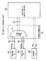
- a line 60 connected to an A station 52 having a virtual path identifier VPI ac and a line 55 connected to a B station 54 having VPI bc are multiplexed by a multiplexer 71 in a cross connector 61 so that they are inputted to a relay switch (or C station) 56 through one line 70, as shown in Fig. 1, it is necessary to refer to both VPI and VCI included in the header portion of each received packet in order that the switch 56 identifies a logical connection on the line 70.
- routing information RT representive of the output line number of the switch in addition to ordinary packet information for each packet in order to switch an input packet to an output line coincident with a logical connection.
- the addition of the routing information RT gives rise to a problem that the length of a packet in the switch becomes large and hence the improvement of a data processing speed in the switch (or a speed conversion) is required in order to ensure the same throughput at the input and output sides of each switch.
- An object of the present invention is to provide a packet switch system and a packet switching method in which the capacity of a table memory for conversion of the header of a received packet can be reduced even if a plurality of logical paths are multiplexed on the same transmission line.
- Another object of the present invention is to provide a packet communication network which is capable of making the size of a packet transmitted in a switch and the size of a packet transmitted on a line outside the switch identical with each other.
- one feature of a packet switch network lies in that an information transfer logical connection having an asymmetrical VCI the value of which differs depending on the direction of transmission of an information packet is formed between two switching stations which communicate with each other.
- any given one of the switching stations upon call set-up designates to the preceding or succeeding switching station the value of VCI which the preceding or succeeding station is to give to an information packet directed to the given station from the preceding or succeeding station.
- each of switching stations constructing the network operates so as to receive a packet which has in a header portion thereof a VCI designated by itself (or that switching station) and to deliver a header label converted packet which includes a VCI designated by the other switching station. Accordingly, for example, in the network, as shown in Fig.
- the present invention allows the C station 56 to determine a CVI to be given to a received packet at every call so that the packet received from the A station 52 and the packet received from the B station 54 always have different VCI's, thereby making it possible to identify a logical connection of each packet by only the VCI.
- Another feature of the present invention lies in that a packet label converting function at each switching station is divisionally arranged in front of and in rear of a switch unit so that an incoming line interface functions to remove a VPI which is included in a packet received from the preceding switching station and becomes unnecessary for a packet switching operation in the switch is eliminated at an incoming line interface and thereinstead to insert routing information RT used in the switch and an outgoing line interface gives a VPI again to a packet to be delivered after the packet switching operation has been finished.
- an internal VCI and routing information used in the switch are set in an input side label conversion table, and a VCI and a VPI for the outgoing line are set in an output side label conversion table.
- a VCI is converted into the internal VCI while the routing information for the switch is set to a VPI field of the packet header.
- the internal VCI is converted into the VCI for the outgoing line while the VCI is given to the packet header.
- Fig. 2 shows the general construction of a network to which the present invention is applicable.
- the network for making a connection between terminal 51 (51a to 51n) and terminals 59 (59a to 59m) includes local switches 52 and 58 for accommodating the terminals 51 and 52, a relay line 55, and relay stations 54 and 56 for communizing the relay line 55 between the local switches 52 and 58 to enhance the traffic processing efficiency.
- a line 60 may be additionally provided between the switches 52 and 56, as shown in Fig. 3A, thereby reducing a load of the relay station 54.
- Fig. 3A shows an example of a physical line construction for realizing the network shown in Fig. 3A.
- a transmission line including the lines 60, 53 and 55 is communized and is distributed by a cross connector 61 to a line which arrives at the relay station (or B station) 54 and a line which makes a relay to the relay station (or C station) 56.
- a unit for identifying a group of logical lines having the same packet transmission direction is given as a virtual path indicator or identifier (VPI) to a packet header.
- VPN virtual path indicator
- the VPI is defined for each line and in each direction thereof, as (VPI ab , VPI ba ) for the line 53, VPI bc , VPI cb ) for the line 55 and (VPI ac , VPI ca ) for the line 60 in Fig. 3B.
- the cross connector 61 distributes each received packet to one of output paths by virtue of the VPI.
- Fig. 1 corresponds to Fig. 3B and shows the cross connector 61 in more detail.
- the line VPI ac from the A station 52 and the line VPI bc from the B station 54 are packet-multiplexed in the cross connector 61 and are thereafter inputted to one line of the C station 56.
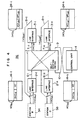
- Fig. 4 shows an example of the construction of a self-routing switch system 56 to which the present invention is applied.
- the present switch system includes a self-routing switch 1 which accommodates n lines therein and performs a packet switching operation, incoming line or input side interfaces 2 (2-1 to 2-n) which are respectively provided for incoming lines 5 (5-1 to 5-n) respectively, outgoing line or output side interfaces 3 (3-1 to 3-n) which are respectively provided for outgoing lines 8 (8-1 to 8-n), and a control unit 4 which performs a call processing.
- Each incoming line interface 2-i is provided in front of the self-routing switch 1 with an input thereof being connected to one incoming line 5-i and with an output thereof being connected to an input line 6-i of the self-routing swich 1.
- each incoming line interface 2-i has a function of converting a virtual logical identifier VCI (or first VCI) in the header portion of an input packet into an internal VCI (IVCI) which is used in the switch and is provided corresponding to each of output lines of the self-routing switch 1 and giving routing information RT indicative of an output line number of the switch 1 to the header portion of the packet.
- VCI virtual logical identifier
- IVCI internal VCI
- Each outgoing line interface 3-i is provided in rear of the self-routing switch 1 with an input thereof being connected to the output line 7-i of the switch 1 and with an output thereof being connected to the outgoing line 8-i.
- each outgoing line interface 3-i has a function of converting the IVCI into an outgoing VCI (or second VCI) and giving a virtual path identifier (VPI).
- the first VCI may be used as an address to read the second VCI.
- the control unit 4 has an input connected to one output line 9 of the switch 1 and an output connected to one input line 10 of the switch 1.
- Figs. 5A to 5C show the formats of signal packets for general information.
- the packet is composed of a header portion H (H1 to H3 fields) and an information portion or user portion INFO.
- a packet inputted from the incoming line 5-i to the line interface 2-i includes an incoming VPI (VPI i ) in an H1 field and an incoming VCI (VCI i ) in an H2 field, as shown in Fig. 5A.
- a packet flowing on the signal lines 6, 7, 9 and 10 includes a number (or routing information) RT indicative of the output line 7-j or 9 of the switch 1 in an H1 field and an internal VCI (IVCI o ) given corresponding to the output line 7-j or 9 in an H2 field, as shown in Fig. 5B.
- a packet outputted from the line interface 3-j to the outgoing line 8-j includes an outgoing VPI (VPI o ) in an H1 field and an outgoing VCI (VCI o ) in an H2 field, as shown in Fig. 5C.
- VPI outgoing VPI
- VCI o outgoing VCI
- the switch 56 corresponds to the C station shown in Fig. 3B
- VCI i and VPI i of the incoming line 5-1 connected to the B station 54 are assumed as VCI bc and VPI bc respectively
- VCI i and VPI i of the incoming line 5-n connected to the D station 58 are assumed as VCI dc and VPI dc respectively
- VCI o and VPI o of the outgoing line connected to the B station 54 are assumed as VCI cb and VPI cb respectively
- VCI o and VPI o of the outgoing line 8-n connected to the d station 58 are assumed as VCI cd and VPI cd respectively.
- Figs. 6A and 6B show the formats of internal control signal packets generated by the control unit 4.
- Fig. 6A shows the format of a packet for setting (or write) of data to the output side label conversion table.
- An H1 field is set with an output line number RT
- an H2 field is set with VCI eo allotted to the output side label conversion table
- fields P1, P2 and P3 of a user portion are respectively set with VPI o and VCI o to be written in the output side label conversion table 24 and an write address IVCI o of the output side label conversion table.
- Fig. 6B shows the format of a packet for setting (or write) of data to the input side label conversion table.
- H1 field is set with an outgoing line number RT
- H2 field is set with VCI ei allotted to the input side label conversion table
- fields P1, P2 and P3 are respectively set with rT and IVCI o to be written in the input side label conversion table and a write address VCIi.
- Fig. 7 shows the details of the incoming line interface 2-i and the outgoing line interface 3-i.
- the incoming line 5-i is connected to an input register 12 and through a delay circuit 11 to an output register 13.
- VCI of packet information inputted to the input register 12 is taken from the H2 field of the input packet into a signal line 15 and is inputted as a read address ot an input side label conversion table 14-i.
- a data output line 16 of the input side label conversion table 14-i is connected to the output register 13 an output of which is inputted to the self-routing switch 1 through a signal line 6-i.
- the output line 7-i of the switch 1 is connected to an input register 22 and through a delay circuit 21 to an output register 23.
- the contents of the H2 field in packet information inputted to the input register 22 are inputted to a separator circuit 26 through a signal line 112 and the contents of the P1 to P3 fields in the inputted packet are outputted onto a signal line 29.
- the separator circuit 26 outputs an enable signal to a signal line 113 in the case where the contents of the H2 field are VCI ei or to a signal line 114 in the case where the contents of the H2 field are VCI eo , so that a gate 116 or 117 is open.
- a packet received from the switch 1 is a packet for setting of data into the input side label conversion table (see Fig.
- the contents (RT, IVCI o , VCI i ) of the P1 to P3 fields of the received packet are inputted through the gate 116 to transmission register 25 from which VCI i is ouputted to a write address line 28 of the input side label conversion table 14-i and RT and IVCI o are outputted to a data line 27, thereby effecting the setting of table data, as shown in the tables 14-1 to 14-n of Fig. 4.
- the received packet is a packet for setting of data into the output side label conversion table (see Fig.
- the contents (VPI o , VCI o ) of the P1 and P2 fields are inputted to a data line of the output side label conversion table through the gate 117 and the contents (IVCI o ) of the P3 field are inputted to a write address line of the output side label conversion table, thereby effecting the setting of table data, as shown in the tables 24-1 to 24-n of Fig. 4.
- the received packet is a general information packet (see Fig.
- IVCI o is outputted from the separator circuit 26 to a read address line 115 so that VPI o and VCI o corresponding to IVCI o are read from the output side label conversion table 24-i onto a data line 111 and the output register 23 outputs to an outgoing line 8-i a header-converted packet which has a format as shown in Fig. 5C.
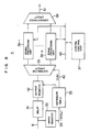
- Fig. 8 shows the details of the construction of the control unit 4 shown in Fig. 4.
- the input line 9 is connected to an input register 32 and through a delay circuit 31 to an output register 42.
- IVCI extracted from the H2 field in a received packet (see Fig. 5B) inputted to the input register 32 is inputted as a read address to a distribute table 33 through a signal line 3.
- An incoming line number LN corresponding to IVCI o which the line interface 2-i gives to the packet directed to the control unit is store din the table 33 and LN read from the table 33 is inputted to a distributer circuit 35 through a signal line 40.
- the distributer circuit 35 inputs the received packet out-putted from the output register 42 to one of a plurality of signal processing units 36-1 to 36-n which makes a one-to-one correspondence to an incoming line 5 selected in accordance with LN. Outputs of the signal processing units 36-1 to 36-n are concentrated by a concentrater circuit 38 and are connected to the input line 10 of the switch 1. Each signal processing unit is connected through a bus 42 to a central control unit 37 which performs a call processing.
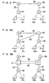
- Stations A, B, C and D in Fig. 9 correspond to the stations 52, 54, 56 and 58 in Fig. 3B.
- the switching operation of the C station will be explained taking as example of a signal sequence a call which arrives the C station through the relay line 55 from the B station and thereafter goes to the D station and a call which arrives the C station through the oblique line 60 from the A station and thereafter goes to the D station.
- IAM initial address message
- the signal packet of IAM 81 includes VPI bc and VCI s allotted to the signal packet in the header portion and includes VCI cb and a dial number DN as the parameters in the information portion.
- the IAM signal packet 81 is inputted to the line interface 2-1 from the line 5-1 (see Fig. 4) connected to the B station 54.
- the packet is inputted to the input register 12 shown in Fig. 7 so that VCI s extracted from the H2 field of the packet header portion is used as an address to make access to the input side label conversion table 14-1.
- VCI s is set or written a record including RT indicative of the output line 9 to which the control unit 4 is connected and IVCI having a value which is allotted corresponging to the incoming line 5-1.
- RT and IVCI read from the table 14-1 through the above-mentioned access are supplied through the data line 16 to the output register 13 in which they are inserted into the packet header portion.
- the self-routing switch 1 outputs the packet received from the input line 6-1 to the output line 9 in accordance with RT included in the header of the packet.
- the packet arriving the control unit 4 through the line 9 is inputted to the input register 32 (shown in Fig. 8) in which IVCI o is extracted from the H2 field of the header portion of the packet.
- the value of IVCI o is outputted onto the data line 39 and is used as an address to make access to the distribute table 33.
- the distribute table 33 outputs to the data line 40 an incoming line number LN which corresponds to IVIC given by the line interface 2-1.
- the distributer circuit 45 distributes the packet to one of the signal processing units 36-1 to 36-n.
- the signal processing unit (36-1 ⁇ 36-n) performs a signal processing which includes, for example, a segmenting/reassembling process (or adaptation layering process) and LAPD (LINK Access Procedure on the D-Channel) and sends a message assembled from the received packet to the central control unit 37. Thereafter, an IAM receive processing program 200 at the central control unit 37 is activated.
- a segmenting/reassembling process or adaptation layering process
- LAPD LINK Access Procedure on the D-Channel
- Fig. 10 shows the flow of a processing by the IAM receive processing program 200.
- vacant information VCI VCI bc in the shown example
- VCI bc vacant information VCI
- IVCI b internal VCI
- a dial number DN included as a parameter in the IAM signal packet is extracted and is subjected to numerical translation to determine an outgoing line number VPI cd (the outgoing line 8-n to the D station 58) (step 206). Further, information VCI dc to be allotted to the incoming line 5-n connected to the D station and paired with the outgoing line 8-n is hunted (step 208) and IVCI d for the output line 7-n of the switch 1 is hunted (step 210).
- VCI s and VPI cd are set or written at an address IVCI of the output side label conversion table 24-n in the line interface 3-n of the outgoing line 8-n connected to the D station (step 212).
- This data setting operation is performed by transmitting an internal signal packet (see Fig. 6A) from the control unit 4 to the line interface 3-n through the line 10, the switch 1 and the line 7-n.
- the H1 field of the internal signal packet is set with routing information RT indicative of the outgoing line 7-n
- the P1 and P2 fields thereof are set with VPI cd and VCI s which are information to be written
- the P3 field thereof is set with IVCI which corresponds to an address of the label conversion table 24-n.
- the IAM signal packet 82 is transmitted to the D station (step 214).
- the IAM signal packet 82 includes, in its H1 and H2 fields, RT indicative of the output line 7-n of the switch 1 corresponding to the outgoing line 8-n connected to the D station and IVCI, respectively and the user portion INFO of the IAM signal packet is set with a signal name IAM, VIC dc as a parameter and DN which is a terminal number in the D station.
- the packet is inputted to the line interface 3-n through the line 10, the switch 1 and the line 7-n.
- the H2 field of the packet header portion is extracted in the input register 22 shown in Fig.
- the conversion table 24 outputs VPI cd and VCI s to the output register 23 through the data line 111.
- the output register 23 inserts the received information (VPI cd and VCI s ) into the header portion of the IAM packet and transmits the header-converted IAM packet to the line 8-n connected to the D station.
- VPI bc , VPI cb , VPI cd , VCI bc , VCI cb , VCI dc , IVCI b and IVCI d are stored (step 216).
- VPI cb is determined by conversion from VPI bc .
- a call set-up completion signal ACM Address Complete Message
- the call set-up completion signal ACM 83 arrives the control unit 4 through the line interface 2-n, the self-routing switch 1 and the line 9, line upon reception of the IAM signal, and an ACM receive processing program 300 shown in Fig. 11 is activated in the central control unit 37.
- the call set-up compeltion signal ACM since the call set-up compeltion signal ACM has been returned from the D station of destination of the call, the following processing is performed for call set-up between the C station and the B station and between the C station and the D station.
- VCI cd and VPI cd are set at an address IVCI d of the output side label conversion table 24-n in the line interface 3-n of the outgoing line 8-n connected to the D station (step 302).
- the setting of data into the output side label conversion table 24-n is effected by transmitting an internal signal packet (having a format shown in Fig. 6A) from the control unit 4 to the line interface 3-n through the line 10, the switch 1 and the line 7-n.
- the H1 field of the internal signal packet is set with RT indicative of the output line 7-n connected to the line interface 3-n
- the H2 field thereof is set with VCI eo
- the P1 and P2 fields thereof are set with VPI cd and VCI cd
- the P3 field thereof is set with IVCI d which is an address of the table 24-n.
- VCI eo identified by the separator circuit 26 and P1, P2 and P3 from the input register 29 are inputted to the output side conversion table 24 through the gate 117.
- the contents VPI cd of the P1 field and the contents VCI cd of the P3 field are set at the address indicated by IVCI d included in the P3 field.
- IVCI b and routing information RT indicative of the output line 7-1 corresponding to the B station are set at an address VCI dc of the input side label conversion table 14-n in the line interface 2-n connected to the incoming line 5-n from the D station (step 304).
- the setting of data to the input side label conversion table 14-n is made by transmitting an internal signal packet in a format shown in Fig. 6B from the control unit 4 to the outgoing line interface 3-n corresponding to the incoming line interface 2-n through the line 10, the switch 1 and the line 7-n.
- the H1 field of the resultant packet is set with RT indicative of the output line 7-n
- the P1 and P2 fields thereof are set with RT indicative of the output line 7-1 corresponding to the B station and IVCI b
- the P3 field thereof is set with a table address VCI dc .
- VCI cb and VPI cb are set at an address VICI b of the output side label conversion table 24-1 in the outgoing line interface 3-1 connected to the B station (step 306), and IVCI d and RT indicative of the output line 7-n corresponding to the D station are set at an address VCI bc of the input side label conversion table 14-1 in the incoming line interface 2-1 connected to the B station (step 308).
- an ACM signal packet 84 including VPI cb and VCI s in its header portion and VCI bc in its user portion is transmitted to the B station (step 310).
- the packet 85 is inputted to the line interface 2-1 through the incoming line 5-1. Then, the H2 field of the received packet is extracted by the input register 12 shown in Fig. 7 and the value of the H2 field or an address VCI bc is supplied to the input side label conversion table 14-1 through the address line 15. Since IVCI d and the routing information RT indicative of the output line 7-n of the switch 1 are set at an address position of the conversion table 14-1 indicated by VCI bc upon call set-up, these information are read to the output register 13 through the data line 16 so that the received packet is subjected to header conversion to provide a format as shown in Fig. 5B.
- the packet arrives the line interface 3-n through the self-routing switch 1 and the line 7-n in accordance with RT of the header portion.
- the H2 field of the received packet is extracted by the input register 22 shown in Fig. 7 and the value IVCI d of the H2 field is inputted as an address to the output side label conversion table 24-n through the signal line 112, the separator circuit 26 and the data line 115.
- VCI cd and VPI cd are set at an address of the conversion table 24-n indicated by IVCI d upon call set-up, these information are read to the output register 23 through the data line 111 and are inserted into the header portion of the packet 85 and the resultant packet is transmitted as a data packet 86 to the outgoing line 8-n connected to the D station.
- VCI dc extracted from the H2 field of the received packet 87 is supplied as an address to the input side label conversion table 14-n. Since IVCI b and the routing information RT indicative of the output line 7-1 are set at an address position of the conversion table 14-n indicated by VCI dc upon call set-up, these information are read to the output register 13 through the data line 16 and are inserted into the header portion of the packet 87.
- the thus header-converted packet arrives the outgoing line interface 3-1 through the self-routing switch 1 and the line 7-1 in accordance with RT of the header portion.
- IVCI b extracted from the H2 field of the received packet is supplied as an address to the output side label conversion table 24-1 throuth the signal line 112, the separator circuit 26 and the address line 115. Since VCI cb and VPI cb are set at an address position of the conversion table 24-1 indicated by IVCI b upon call set-up, these information are read to the output register 23 through the data line 111 and are inserted into the header portion of the received packet 87 and the resultant packet is transmitted as a data packet 88 to the outgoing line 8-1 connected to the B station.
Applications Claiming Priority (2)
| Application Number | Priority Date | Filing Date | Title |
|---|---|---|---|
| JP171789/89 | 1989-07-05 | ||
| JP17178989A JP2892689B2 (ja) | 1989-07-05 | 1989-07-05 | パケット通信網およびパケット交換機 |
Publications (3)
| Publication Number | Publication Date |
|---|---|
| EP0406842A2 true EP0406842A2 (de) | 1991-01-09 |
| EP0406842A3 EP0406842A3 (en) | 1993-05-05 |
| EP0406842B1 EP0406842B1 (de) | 1997-01-22 |
Family
ID=15929722
Family Applications (1)
| Application Number | Title | Priority Date | Filing Date |
|---|---|---|---|
| EP90112790A Expired - Lifetime EP0406842B1 (de) | 1989-07-05 | 1990-07-04 | Paketvermittlungsnetzwerk für Kommunikation mit Verwendung von Paketen mit virtueller Verbindungserkennung VCI |
Country Status (5)
| Country | Link |
|---|---|
| US (1) | US5119369A (de) |
| EP (1) | EP0406842B1 (de) |
| JP (1) | JP2892689B2 (de) |
| CA (1) | CA2020244C (de) |
| DE (1) | DE69029764T2 (de) |
Cited By (8)
| Publication number | Priority date | Publication date | Assignee | Title |
|---|---|---|---|---|
| AU634930B2 (en) * | 1991-03-05 | 1993-03-04 | Fujitsu Limited | Logical channel setting system for atm network |
| FR2681164A1 (fr) * | 1991-09-06 | 1993-03-12 | Thomson Csf | Procede pour l'acheminement d'un paquet de donnees dans un reseau de transmission numerique. |
| WO1994021069A1 (en) * | 1993-03-10 | 1994-09-15 | Telefonaktiebolaget Lm Ericsson | Label handling in packet networks |
| GB2285366A (en) * | 1993-12-30 | 1995-07-05 | Samsung Electronics Co Ltd | Asynchronous data transfer |
| WO1999008473A1 (en) * | 1997-08-08 | 1999-02-18 | Northern Telecom Limited | System and method for establishing a communication connection |
| EP0933965A2 (de) * | 1997-12-01 | 1999-08-04 | Nortel Networks Corporation | Kommunikationssystem mit Kommunikationsschnittstelle zur Lastverteilung |
| WO2000002412A1 (de) * | 1998-07-03 | 2000-01-13 | Siemens Aktiengesellschaft | Verfahren zum einrichten eines leitweges über ein kommunikationsnetz |
| WO2012085898A3 (en) * | 2010-12-24 | 2013-04-11 | Telefonaktiebolaget Lm Ericsson (Publ) | Method and system for intra-node header compression |
Families Citing this family (63)
| Publication number | Priority date | Publication date | Assignee | Title |
|---|---|---|---|---|
| JP2555906B2 (ja) * | 1990-05-18 | 1996-11-20 | 日本電気株式会社 | Atmセルのvci変換方式 |
| JP2993715B2 (ja) * | 1990-08-17 | 1999-12-27 | 株式会社日立製作所 | Atmスイッチおよびその制御方法 |
| JPH04229747A (ja) * | 1990-08-17 | 1992-08-19 | Hitachi Ltd | パケット交換方法、およびパケット交換システム |
| DE4027611A1 (de) * | 1990-08-31 | 1992-03-05 | Philips Patentverwaltung | Koppelfeld fuer ein asynchrones zeitvielfachuebermittlungssystem |
| US20020101871A1 (en) * | 1991-01-31 | 2002-08-01 | Fujitsu Limited | Connectionless communication system |
| WO1992014321A1 (en) * | 1991-01-31 | 1992-08-20 | Fujitsu Limited | Connectionless communication system |
| US5809012A (en) * | 1991-01-31 | 1998-09-15 | Fujitsu Limited | Connectionless communication system |
| US5313453A (en) * | 1991-03-20 | 1994-05-17 | Fujitsu Limited | Apparatus for testing ATM channels |
| JP2892180B2 (ja) * | 1991-04-30 | 1999-05-17 | 富士通株式会社 | Atmクロスコネクト装置の監視方式 |
| US5321813A (en) | 1991-05-01 | 1994-06-14 | Teradata Corporation | Reconfigurable, fault tolerant, multistage interconnect network and protocol |
| JPH0530132A (ja) * | 1991-07-24 | 1993-02-05 | Fujitsu Ltd | Atm網における課金方式 |
| DE69132536T2 (de) * | 1991-08-21 | 2001-10-04 | Ibm | Verbindungslose ATM-Datendienste |
| JPH05130134A (ja) * | 1991-11-08 | 1993-05-25 | Fujitsu Ltd | Atm交換における系切替方式 |
| JP3262142B2 (ja) | 1992-01-16 | 2002-03-04 | 富士通株式会社 | Atmセル化装置、atmセル化方法、ノード、及びノードにおける多重化方法 |
| JPH05244187A (ja) * | 1992-02-14 | 1993-09-21 | Nippon Telegr & Teleph Corp <Ntt> | 装置内監視方法 |
| US5357510A (en) * | 1992-02-19 | 1994-10-18 | Fujitsu Limited | Apparatus and a method for supervising and controlling ATM traffic |
| ATE208975T1 (de) * | 1992-06-26 | 2001-11-15 | Siemens Ag | Verfahren zur behandlung der im kopfteil von im asynchronen transfermodus übertragenen nachrichtenzellen enthaltenden informationen |
| DE4230743C2 (de) * | 1992-09-14 | 1994-03-17 | Siemens Ag | Verfahren zum Rundsenden von Zellen in einer im Asynchron-Transfer-Modus wirkenden Koppelstruktur eines Kommunikationssystems |
| EP0666004A4 (de) * | 1992-10-21 | 1999-11-03 | Bell Communications Res | Virtueller privater breitband-netzwerkdienst und system. |
| JP2953924B2 (ja) * | 1992-10-21 | 1999-09-27 | 日本電気株式会社 | パケット通信における私設網構成方法およびシステム |
| US5418782A (en) * | 1992-10-30 | 1995-05-23 | Scientific-Atlanta, Inc. | Methods and apparatus for providing virtual service selection in a multi-service communications system |
| SE515274C2 (sv) * | 1992-11-09 | 2001-07-09 | Ericsson Telefon Ab L M | Paketväljare för telekommunikationsanläggning |
| US5345558A (en) * | 1992-11-23 | 1994-09-06 | Synoptics Communications, Inc. | Topology independent broadcast of cells in an ATM network or the like |
| KR100293920B1 (ko) * | 1993-06-12 | 2001-09-17 | 윤종용 | 비동기전송모드의사용자망접속인터페이스의트래픽제어장치및방법 |
| JP3167228B2 (ja) * | 1993-09-20 | 2001-05-21 | 富士通株式会社 | Vccテーブルのアクセス方法及びバーチャルチャネル変換装置 |
| DE4340329C2 (de) * | 1993-11-26 | 2002-06-20 | Tenovis Gmbh & Co Kg | Verfahren zur Erzeugung von Leitadressen für in einem nach dem asynchronen Transfermodus (ATM) arbeitenden Vermittlungssystem zu übertragende Pakete |
| US5425101A (en) * | 1993-12-03 | 1995-06-13 | Scientific-Atlanta, Inc. | System and method for simultaneously authorizing multiple virtual channels |
| JP3464034B2 (ja) * | 1994-03-18 | 2003-11-05 | 富士通株式会社 | Atm遠隔保守用コネクション設定方式 |
| US5515370A (en) * | 1994-03-31 | 1996-05-07 | Siemens Aktiengesellschaft | Circuit arrangement for line units of an ATM switching equipment |
| EP0680235B1 (de) * | 1994-04-28 | 2001-09-12 | Hewlett-Packard Company, A Delaware Corporation | Erzeugung von Kanalsidentifizierer |
| EP0680236A1 (de) * | 1994-04-29 | 1995-11-02 | International Business Machines Corporation | Vorrichtung zum Austauschen von Eingangswerten durch entsprechende Ausgangswerte |
| IT1278517B1 (it) * | 1994-07-25 | 1997-11-24 | Motorola Inc | Procedimento per il trasferimento intersatellitare di pacchetti di dati. |
| JP3224963B2 (ja) * | 1994-08-31 | 2001-11-05 | 株式会社東芝 | ネットワーク接続装置及びパケット転送方法 |
| KR0132959B1 (ko) * | 1994-12-22 | 1998-04-21 | 양승택 | 비동기 전달모드(atm)망에서 비연결형 데이터 서비스 제공을 위한 비연결형 서버 |
| US5550816A (en) * | 1994-12-29 | 1996-08-27 | Storage Technology Corporation | Method and apparatus for virtual switching |
| US5627836A (en) * | 1995-01-31 | 1997-05-06 | Bell Atlantic Network Services, Inc. | VPI/VCI administration |
| US5666361A (en) * | 1995-04-05 | 1997-09-09 | International Business Machines Corporation | ATM cell forwarding and label swapping method and apparatus |
| US5668798A (en) * | 1995-04-05 | 1997-09-16 | International Business Machines Corporation | Multiplexed TC sublayer for ATM switch |
| US5600378A (en) * | 1995-05-22 | 1997-02-04 | Scientific-Atlanta, Inc. | Logical and composite channel mapping in an MPEG network |
| US6215530B1 (en) | 1995-05-22 | 2001-04-10 | Scientific-Atlanta, Inc. | Logical and composite channel mapping in an MPEG network |
| JPH08331137A (ja) * | 1995-05-31 | 1996-12-13 | Fujitsu Ltd | Smds交換装置 |
| US6002667A (en) * | 1995-07-19 | 1999-12-14 | Fujitsu Network Communications, Inc. | Minimum guaranteed cell rate method and apparatus |
| JPH11512583A (ja) * | 1995-09-14 | 1999-10-26 | フジツウ ネットワーク コミュニケーションズ,インコーポレイテッド | 広域atm網内のバッファ割付用送信側制御式フロー制御 |
| US6016319A (en) * | 1995-10-31 | 2000-01-18 | Lucent Technologies, Inc. | Communications system for transmission of datagram packets over connection-oriented networks |
| DE69534231T2 (de) * | 1995-11-07 | 2006-01-19 | Alcatel | Verfahren und Einrichtung zur Verwaltung von Mehrfachverbindungen |
| AU1697697A (en) * | 1996-01-16 | 1997-08-11 | Fujitsu Limited | A reliable and flexible multicast mechanism for atm networks |
| US5757796A (en) * | 1996-04-26 | 1998-05-26 | Cascade Communications Corp. | ATM address translation method and apparatus |
| US6151324A (en) * | 1996-06-03 | 2000-11-21 | Cabletron Systems, Inc. | Aggregation of mac data flows through pre-established path between ingress and egress switch to reduce number of number connections |
| KR980007190A (ko) * | 1996-06-12 | 1998-03-30 | 김광호 | 유휴 가상 패스 식별자와 가상 채널 식별자의 수 계산회로 |
| KR0174690B1 (ko) | 1996-08-13 | 1999-04-01 | 삼성전자주식회사 | 교환기에서 비동기 전송모드 인터프로세서 통신셀의 다중화/역다중화방법 및시스템 |
| US5748905A (en) * | 1996-08-30 | 1998-05-05 | Fujitsu Network Communications, Inc. | Frame classification using classification keys |
| GB9621775D0 (en) * | 1996-10-18 | 1996-12-11 | Northern Telecom Ltd | ATM communications system and method |
| JP3579208B2 (ja) * | 1997-03-11 | 2004-10-20 | 株式会社東芝 | ノード装置及びメッセージ交換方法 |
| JPH11154954A (ja) | 1997-11-20 | 1999-06-08 | Hitachi Ltd | Atmスイッチ |
| US6693904B1 (en) * | 1998-04-09 | 2004-02-17 | Lucent Technologies Inc. | Trace format for a sliced switch fabric |
| JP3537318B2 (ja) | 1998-07-24 | 2004-06-14 | 富士通株式会社 | 特定のコネクションの通信データを加工する交換機および交換方法 |
| DE19843626B4 (de) | 1998-09-23 | 2005-02-03 | Siemens Ag | Verfahren zum Ermitteln einer Netzzugangsadresse |
| US6745240B1 (en) | 1999-11-15 | 2004-06-01 | Ncr Corporation | Method and apparatus for configuring massively parallel systems |
| US6519697B1 (en) | 1999-11-15 | 2003-02-11 | Ncr Corporation | Method and apparatus for coordinating the configuration of massively parallel systems |
| US6412002B1 (en) | 1999-11-15 | 2002-06-25 | Ncr Corporation | Method and apparatus for selecting nodes in configuring massively parallel systems |
| US6418526B1 (en) | 1999-11-15 | 2002-07-09 | Ncr Corporation | Method and apparatus for synchronizing nodes in massively parallel systems |
| US6901073B2 (en) * | 2001-02-14 | 2005-05-31 | Northrop Grumman Corporation | Encapsulation method and apparatus for communicating fixed-length data packets through an intermediate network |
| FR2939260A1 (fr) * | 2008-11-28 | 2010-06-04 | France Telecom | Procede de configuration d'un circuit virtuel |
Citations (5)
| Publication number | Priority date | Publication date | Assignee | Title |
|---|---|---|---|---|
| WO1984000267A1 (en) * | 1982-06-25 | 1984-01-19 | Western Electric Co | Fast packet switching system |
| GB2168222A (en) * | 1984-11-27 | 1986-06-11 | Kokusai Denshin Denwa Co Ltd | Data packet switching system |
| EP0234191A2 (de) * | 1986-01-09 | 1987-09-02 | Nec Corporation | Paketvermitteltes Fernmeldenetz mit parallelen virtuellen Verbindungen zur Umweglenkung von Nachrichtenpaketen |
| EP0279443A2 (de) * | 1987-02-19 | 1988-08-24 | Fujitsu Limited | Verfahren und System für eine kopfgeleitete Vermittlung von Datenpaketen |
| AU2507388A (en) * | 1987-11-11 | 1989-05-25 | Nec Corporation | Frame relay type data switching apparatus |
Family Cites Families (2)
| Publication number | Priority date | Publication date | Assignee | Title |
|---|---|---|---|---|
| DE58906063D1 (de) * | 1988-02-19 | 1993-12-09 | Siemens Ag | Verfahren zum Einrichten von über Koppelvielfache einer mehrstufigen Koppelanordnung verlaufenden virtuellen Verbindungen. |
| JP2753254B2 (ja) * | 1988-04-06 | 1998-05-18 | 株式会社日立製作所 | パケツト交換システム |
-
1989
- 1989-07-05 JP JP17178989A patent/JP2892689B2/ja not_active Expired - Fee Related
-
1990
- 1990-06-29 CA CA002020244A patent/CA2020244C/en not_active Expired - Fee Related
- 1990-07-03 US US07/547,216 patent/US5119369A/en not_active Expired - Lifetime
- 1990-07-04 DE DE69029764T patent/DE69029764T2/de not_active Expired - Fee Related
- 1990-07-04 EP EP90112790A patent/EP0406842B1/de not_active Expired - Lifetime
Patent Citations (5)
| Publication number | Priority date | Publication date | Assignee | Title |
|---|---|---|---|---|
| WO1984000267A1 (en) * | 1982-06-25 | 1984-01-19 | Western Electric Co | Fast packet switching system |
| GB2168222A (en) * | 1984-11-27 | 1986-06-11 | Kokusai Denshin Denwa Co Ltd | Data packet switching system |
| EP0234191A2 (de) * | 1986-01-09 | 1987-09-02 | Nec Corporation | Paketvermitteltes Fernmeldenetz mit parallelen virtuellen Verbindungen zur Umweglenkung von Nachrichtenpaketen |
| EP0279443A2 (de) * | 1987-02-19 | 1988-08-24 | Fujitsu Limited | Verfahren und System für eine kopfgeleitete Vermittlung von Datenpaketen |
| AU2507388A (en) * | 1987-11-11 | 1989-05-25 | Nec Corporation | Frame relay type data switching apparatus |
Cited By (15)
| Publication number | Priority date | Publication date | Assignee | Title |
|---|---|---|---|---|
| AU634930B2 (en) * | 1991-03-05 | 1993-03-04 | Fujitsu Limited | Logical channel setting system for atm network |
| US5394393A (en) * | 1991-09-06 | 1995-02-28 | Thomson-Csf | Method for the routing of a packet of data in a digital transmission network |
| FR2681164A1 (fr) * | 1991-09-06 | 1993-03-12 | Thomson Csf | Procede pour l'acheminement d'un paquet de donnees dans un reseau de transmission numerique. |
| EP0537036A1 (de) * | 1991-09-06 | 1993-04-14 | Thomson-Csf | Leitweglenkungsverfahren für Datenpakete in einem digitalen Übertragungsnetzwerk |
| US5546387A (en) * | 1993-03-10 | 1996-08-13 | Telefonakteibolaget Lm Ericsson | Label handling in packet networks |
| WO1994021069A1 (en) * | 1993-03-10 | 1994-09-15 | Telefonaktiebolaget Lm Ericsson | Label handling in packet networks |
| AU696446B2 (en) * | 1993-03-10 | 1998-09-10 | Telefonaktiebolaget Lm Ericsson (Publ) | Label handling in packet networks |
| GB2285366A (en) * | 1993-12-30 | 1995-07-05 | Samsung Electronics Co Ltd | Asynchronous data transfer |
| GB2285366B (en) * | 1993-12-30 | 1998-07-15 | Samsung Electronics Co Ltd | Asychronous data transfer |
| WO1999008473A1 (en) * | 1997-08-08 | 1999-02-18 | Northern Telecom Limited | System and method for establishing a communication connection |
| EP0933965A2 (de) * | 1997-12-01 | 1999-08-04 | Nortel Networks Corporation | Kommunikationssystem mit Kommunikationsschnittstelle zur Lastverteilung |
| EP0933965A3 (de) * | 1997-12-01 | 2000-05-24 | Nortel Networks Corporation | Kommunikationssystem mit Kommunikationsschnittstelle zur Lastverteilung |
| WO2000002412A1 (de) * | 1998-07-03 | 2000-01-13 | Siemens Aktiengesellschaft | Verfahren zum einrichten eines leitweges über ein kommunikationsnetz |
| US6940858B1 (en) | 1998-07-03 | 2005-09-06 | Siemens Aktiengesellschaft | Method for establishing a route via a communications network |
| WO2012085898A3 (en) * | 2010-12-24 | 2013-04-11 | Telefonaktiebolaget Lm Ericsson (Publ) | Method and system for intra-node header compression |
Also Published As
| Publication number | Publication date |
|---|---|
| CA2020244C (en) | 1994-03-01 |
| CA2020244A1 (en) | 1991-01-06 |
| US5119369A (en) | 1992-06-02 |
| DE69029764D1 (de) | 1997-03-06 |
| EP0406842A3 (en) | 1993-05-05 |
| JPH0338141A (ja) | 1991-02-19 |
| JP2892689B2 (ja) | 1999-05-17 |
| DE69029764T2 (de) | 1997-08-07 |
| EP0406842B1 (de) | 1997-01-22 |
Similar Documents
| Publication | Publication Date | Title |
|---|---|---|
| EP0406842B1 (de) | Paketvermittlungsnetzwerk für Kommunikation mit Verwendung von Paketen mit virtueller Verbindungserkennung VCI | |
| US5410540A (en) | Shared-buffer-type ATM switch having copy function and copy method thereof | |
| US5577037A (en) | Method of processing inclusively STM signals and ATM signals and switching system employing the same | |
| EP0112340B1 (de) | Speicheranordnung für durchgehende nachrichten in einer leitungssteuerung | |
| EP0838110B1 (de) | Fernmeldeanordnung und -verfahren | |
| US5805588A (en) | Circuit emulating exchange using micro cells | |
| US5841771A (en) | Telecommunications switch apparatus and method for time switching | |
| US5546387A (en) | Label handling in packet networks | |
| US5303236A (en) | Signalling apparatus for use in an ATM switching system | |
| EP0683949B1 (de) | Verfahren zur behandlung redundanter vermittlungsebenen in paketvermittlungen und vermittlung zur durchführung des verfahrens | |
| US6324164B1 (en) | Asynchronous transfer mode (A.T.M.) protocol adapter for a high speed cell switching system | |
| US6101184A (en) | Data switching method and data switching apparatus for efficiently handling scan data in information communication network | |
| EP0355797B1 (de) | Signalisierungsgerät zur Verwendung in einem ATM-Vermittlungssystem | |
| CA2120542C (en) | Cell relay transport mechanism | |
| US5715251A (en) | Local network including concentric main and relief rings | |
| EP1052813A1 (de) | Telekommunikationsvorrichtung und -verfahren | |
| US20010009549A1 (en) | Method of injecting/extracting control cells in an asynchronous transfer mode (ATM) network | |
| JP3070545B2 (ja) | パケット通信網及びパケット交換機 | |
| JP3055547B2 (ja) | セル組立方法、セル分解方法、およびatmセル通信装置 | |
| JPH10511244A (ja) | 一定ビット・レート(cbr)データに対するatmアダプタ・ポート | |
| JPH1146200A (ja) | Atm交換機 | |
| JPH11317740A (ja) | Atm交換機 | |
| JPH11317741A (ja) | Atm通信装置 | |
| JPH11317738A (ja) | Atm交換機 |
Legal Events
| Date | Code | Title | Description |
|---|---|---|---|
| PUAI | Public reference made under article 153(3) epc to a published international application that has entered the european phase |
Free format text: ORIGINAL CODE: 0009012 |
|
| AK | Designated contracting states |
Kind code of ref document: A2 Designated state(s): DE FR GB |
|
| 17P | Request for examination filed |
Effective date: 19901220 |
|
| PUAL | Search report despatched |
Free format text: ORIGINAL CODE: 0009013 |
|
| AK | Designated contracting states |
Kind code of ref document: A3 Designated state(s): DE FR GB |
|
| 17Q | First examination report despatched |
Effective date: 19940729 |
|
| GRAH | Despatch of communication of intention to grant a patent |
Free format text: ORIGINAL CODE: EPIDOS IGRA |
|
| GRAH | Despatch of communication of intention to grant a patent |
Free format text: ORIGINAL CODE: EPIDOS IGRA |
|
| GRAA | (expected) grant |
Free format text: ORIGINAL CODE: 0009210 |
|
| AK | Designated contracting states |
Kind code of ref document: B1 Designated state(s): DE FR GB |
|
| REF | Corresponds to: |
Ref document number: 69029764 Country of ref document: DE Date of ref document: 19970306 |
|
| ET | Fr: translation filed | ||
| PLBE | No opposition filed within time limit |
Free format text: ORIGINAL CODE: 0009261 |
|
| STAA | Information on the status of an ep patent application or granted ep patent |
Free format text: STATUS: NO OPPOSITION FILED WITHIN TIME LIMIT |
|
| 26N | No opposition filed | ||
| REG | Reference to a national code |
Ref country code: GB Ref legal event code: IF02 |
|
| PGFP | Annual fee paid to national office [announced via postgrant information from national office to epo] |
Ref country code: FR Payment date: 20020619 Year of fee payment: 13 |
|
| PGFP | Annual fee paid to national office [announced via postgrant information from national office to epo] |
Ref country code: GB Payment date: 20020621 Year of fee payment: 13 |
|
| PGFP | Annual fee paid to national office [announced via postgrant information from national office to epo] |
Ref country code: DE Payment date: 20020916 Year of fee payment: 13 |
|
| PG25 | Lapsed in a contracting state [announced via postgrant information from national office to epo] |
Ref country code: GB Free format text: LAPSE BECAUSE OF NON-PAYMENT OF DUE FEES Effective date: 20030704 |
|
| PG25 | Lapsed in a contracting state [announced via postgrant information from national office to epo] |
Ref country code: DE Free format text: LAPSE BECAUSE OF NON-PAYMENT OF DUE FEES Effective date: 20040203 |
|
| GBPC | Gb: european patent ceased through non-payment of renewal fee |
Effective date: 20030704 |
|
| PG25 | Lapsed in a contracting state [announced via postgrant information from national office to epo] |
Ref country code: FR Free format text: LAPSE BECAUSE OF NON-PAYMENT OF DUE FEES Effective date: 20040331 |
|
| REG | Reference to a national code |
Ref country code: FR Ref legal event code: ST |