EP0394216B1 - Procédé de commande et de régulation d'un moteur à combustion - Google Patents
Procédé de commande et de régulation d'un moteur à combustion Download PDFInfo
- Publication number
- EP0394216B1 EP0394216B1 EP90890118A EP90890118A EP0394216B1 EP 0394216 B1 EP0394216 B1 EP 0394216B1 EP 90890118 A EP90890118 A EP 90890118A EP 90890118 A EP90890118 A EP 90890118A EP 0394216 B1 EP0394216 B1 EP 0394216B1
- Authority
- EP
- European Patent Office
- Prior art keywords
- signal
- binary
- comparator
- value
- bit
- Prior art date
- Legal status (The legal status is an assumption and is not a legal conclusion. Google has not performed a legal analysis and makes no representation as to the accuracy of the status listed.)
- Expired - Lifetime
Links
- 238000000034 method Methods 0.000 title claims abstract description 9
- 238000002485 combustion reaction Methods 0.000 title claims abstract description 6
- 230000033228 biological regulation Effects 0.000 title description 2
- 230000001276 controlling effect Effects 0.000 claims description 6
- 230000001105 regulatory effect Effects 0.000 claims description 4
- 230000009977 dual effect Effects 0.000 description 5
- 239000000446 fuel Substances 0.000 description 5
- 238000002347 injection Methods 0.000 description 5
- 239000007924 injection Substances 0.000 description 5
- 230000001419 dependent effect Effects 0.000 description 4
- 230000008901 benefit Effects 0.000 description 3
- 238000001914 filtration Methods 0.000 description 3
- 230000008859 change Effects 0.000 description 2
- 230000007423 decrease Effects 0.000 description 2
- 238000010586 diagram Methods 0.000 description 2
- 230000006872 improvement Effects 0.000 description 2
- 239000004065 semiconductor Substances 0.000 description 2
- 238000006243 chemical reaction Methods 0.000 description 1
- 230000006866 deterioration Effects 0.000 description 1
- 230000000694 effects Effects 0.000 description 1
- 230000008030 elimination Effects 0.000 description 1
- 238000003379 elimination reaction Methods 0.000 description 1
- 230000002349 favourable effect Effects 0.000 description 1
- 230000009467 reduction Effects 0.000 description 1
- 230000004044 response Effects 0.000 description 1
- 239000000243 solution Substances 0.000 description 1
- 238000011144 upstream manufacturing Methods 0.000 description 1
Images
Classifications
-
- F—MECHANICAL ENGINEERING; LIGHTING; HEATING; WEAPONS; BLASTING
- F02—COMBUSTION ENGINES; HOT-GAS OR COMBUSTION-PRODUCT ENGINE PLANTS
- F02D—CONTROLLING COMBUSTION ENGINES
- F02D35/00—Controlling engines, dependent on conditions exterior or interior to engines, not otherwise provided for
- F02D35/0007—Controlling engines, dependent on conditions exterior or interior to engines, not otherwise provided for using electrical feedback
-
- F—MECHANICAL ENGINEERING; LIGHTING; HEATING; WEAPONS; BLASTING
- F02—COMBUSTION ENGINES; HOT-GAS OR COMBUSTION-PRODUCT ENGINE PLANTS
- F02D—CONTROLLING COMBUSTION ENGINES
- F02D41/00—Electrical control of supply of combustible mixture or its constituents
- F02D41/30—Controlling fuel injection
- F02D41/3005—Details not otherwise provided for
-
- F—MECHANICAL ENGINEERING; LIGHTING; HEATING; WEAPONS; BLASTING
- F02—COMBUSTION ENGINES; HOT-GAS OR COMBUSTION-PRODUCT ENGINE PLANTS
- F02D—CONTROLLING COMBUSTION ENGINES
- F02D41/00—Electrical control of supply of combustible mixture or its constituents
- F02D41/30—Controlling fuel injection
- F02D41/38—Controlling fuel injection of the high pressure type
- F02D41/40—Controlling fuel injection of the high pressure type with means for controlling injection timing or duration
- F02D41/406—Electrically controlling a diesel injection pump
- F02D41/407—Electrically controlling a diesel injection pump of the in-line type
Definitions
- the invention relates to a method for controlling and regulating an internal combustion engine according to the preamble of claim 1 and to an electronic regulating and control device for internal combustion engines according to the preamble of claim 3.
- a controller delivers a digital output signal.
- an electromechanical drive for the actuator e.g. the injection pump or pump nozzles.
- a pulse width modulator with a downstream low-pass filter is then advantageously used as the digital-to-analog converter. It must be taken into account here that, due to its electrical (inductance) and mechanical (mass) properties, the drive exhibits a more or less pronounced low-pass behavior that plays a role in the dimensioning of the low-pass filter.
- the actuator may in any case be mechanically unsteady, namely an oscillating movement with the clock frequency of the control signal.
- the effort required for the low-pass filter, particularly at lower clock frequencies, is to be regarded as a disadvantage.
- pulse-width modulated signals for controlling actuators for the injection quantity is evident, for example, from DE-A-33 11 351, in which case the actuator is controlled directly by the pulse-width-modulated signals.
- the applicant's DE-A-37 30 443 also shows the use of a pulse-width-modulated signal, but this signal is used here as a command variable for a servo circuit for the actuator.
- control signal for controlling an electromechanical actuator is thus to be understood in the sense that it includes direct control as well as control of a servo circuit for the actuator.
- Document JP-A-59 120 776 discloses a speed-dependent control of a fuel pump, which is carried out in such a way that a speed-dependent pulse train is fed to a monostable multivibrator, which forms a speed-dependent pulse from the pulse train, the individual pulses of which have a constant duration.
- This pulse is fed to a fuel pump. Accordingly, the pulse duty factor increases with increasing speed and, on average, more electrical energy is supplied to the fuel pump.
- Such a control is unsuitable in the sense of the documents mentioned above.
- a pulse width modulator for converting a dual digital value into a pulse width modulated signal can, for example from the company publication "Embedded Controller Handbook", Intel, Order Number 21 09 18-005, 1987.
- the digital value is fed to a register, at whose output the value is, for example, 8 digits (in the dual system).
- a clock frequency is fed to a counter input, the 8-digit output of which is also compared in a comparator with the previously mentioned value.
- the output of the comparator which checks for equality, is fed to the reset input of a flip-flop, the set input of which receives the overflow signal from the counter.
- a pulse width modulated signal is then present at the Q output of the flip-flop. This signal has a pulse within each cycle, the width or length of which increases with increasing size of the value mentioned. With a register value 0 the width of the pulse disappears, with a register value 255 the width almost corresponds to the period T o .
- the invention has set itself the goal of converting the pulse instead of the usual pulse width modulation To create output signals of the computing device in a control signal for an electromechanical actuator, which has the same effort, in particular with respect to the filtering, significantly lower relative voltage fluctuations of the analog signal.
- This goal can be achieved with a method according to the characterizing part of claim 1 or with a device according to the characterizing part of claim 3.
- the invention offers the advantage that, with the same circuit complexity as according to the prior art, a significant reduction in the ripple of the output signal is obtained. With the same demands on the residual ripple, the outlay for a downstream low-pass filter can be kept considerably lower than according to the prior art.
- downstream low-pass filter here also includes a consumer with a low-pass character, which has already been explained above.
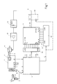
- FIG. 1 shows an exemplary embodiment of a device according to the invention in a block diagram
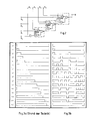
- FIG. 2 shows another exemplary embodiment of a device according to the invention
- FIGS. 3a and b show the form of the output signal as a function of the preset signal in a device in time diagrams within one cycle according to the prior art (Fig. 3a) or in a device according to the invention (Fig. 3b).
- Fig. 1 shows schematically a diesel engine 1 with an injection pump 2, the control rod 3 determining the amount of fuel supplied is adjustable by means of an electromechanical drive 4.
- a computing device 5 calculates from operating variable signals of the engine 1 and also the Vehicle output signal b, which is the basis for the adjustment of the control rod 3.
- Essential operating variables as input variables of the computing device 5 are the accelerator pedal position, which generates a corresponding signal f via a transmitter 7 and the speed of the engine 1, a speed signal n being supplied by a speed transmitter 8 to the computing device 5.
- Fig. 1 further sensors 9 are indicated schematically, the additional operating quantity signals, e.g. in terms of engine temperature, air pressure, fuel temperature etc.
- the output signal b of the computing device 5 and any further output signals b ', b ⁇ is in digital, dual-coded form and is fed to a register 10, from where it has 8 digits as word B to the inputs B0 to B7 of an 8-bit comparator 11 arrives.
- a comparator can be implemented, for example, with logic modules MM54C85, 4-bit magnitude comparator from National Semiconducter.
- the company publication "Logic Databook, Volume 1, National Semiconductor Corporation", 1984 shows the logical structure of such modules and describes their interconnection to word lengths that are greater than 4 bits.
- a dual counter 12 which is supplied with a counting cycle f 1 of the period T 1.
- This counting clock expediently comes from a clock generator, which is required by the computing device 5 and is not shown in detail.
- An 8-digit output of the counter 12 is connected to the second input of the comparator 11, but here the counter output is connected to the comparator input in such a way that the output MSB (most significant bit) of the counter 12 corresponds to the Input A0 of the comparator 11 with the lowest position value (LSB) corresponds, ie the order of the positions is reversed when wiring, or, in other words, the counter signal a is fed to the comparator 11 in inverted form.
- the comparator 11 which checks whether the word A at the inputs A0 to A7 is smaller than the word B at the inputs B0 to B7, a drive signal of the period T0 occurs, which consists of individual pulses within each period, the Total length within each period T0 is proportional to the value of the output signal b of the computing device 5. For a 4-bit comparator, this is illustrated in FIG. 3b, with the previously customary pulse width modulation being compared in FIG. 3a. The default value B is numbered 0 to 15 on the left.
- the word length is shown with 8 bits, in Fig. 3 with 4 bits. In practice, however, word lengths of 8 to 16 bits or more will be used.
- the output of the comparator 11 can be followed by a D flip-flop 13 which is clock-edge-controlled by the counter clock f 1 and frees the control signal from switching spikes which arise in the comparator 11.
- An inverter is upstream of the clock input of the flip-flop 13. The elimination of switching spikes is particularly advisable at higher clock frequencies, when run times in the comparator lead to spikes of a clearly noticeable length, which could cause the predefined signal to be falsified.
- the control signal s is fed to the electromechanical drive 4 via a simple low-pass filter 14 and an output stage 15.
- Fig. 2 shows an implementation example of a 4-bit comparator using conventional gate modules and Fig. 3b, as already mentioned, the associated control signal for the sixteen possible default values. From Fig. 3b the person skilled in the art already sees the significant improvement in the ripple of a voltage obtained after filtering. Of course, this improvement is also shown mathematically and experimentally and is given below with the aid of a comparison for the worst case of the pulse duty factor (eg number 8 in FIG. 3a).
- these voltage fluctuations are at the same filter time constant 4 bits below 12% 10 bits under 0.2% 16 bits under 40.10 ⁇ 6
- Actuators that are to be controlled based on the output signal b of the computing device 5 are, in particular, the control rod of an injection pump, as shown in FIG. 1. But it can also be actuators for adjusting the injection timing, the amount of air, an exhaust gas recirculation valve, a throttle valve and the like. What is indicated by signals b ', b ⁇ in Fig. 1.
- a particular advantage associated with the invention can be seen in the rapid and error-free response to a change in the default value, which is not only given by the more favorable filter dimensioning. you alleviate within the period T o the default value B to a particularly smaller value, then a reaction in the desired direction is shown in almost all cases with the structure according to the invention even before the end of the same period. In the case of the prior art, in the worst case, if the default value changes during the period, either so-called outliers (one-time output of 100%) occur, or the desired change does not occur until the next period T o . Such misconduct can have fatal consequences for driving the motor vehicle.
- the total duration of the control signal s is essentially proportional to the value of the dual or binary output signal b, this should not mean that a direct component (offset) is excluded.
Landscapes
- Engineering & Computer Science (AREA)
- Chemical & Material Sciences (AREA)
- Combustion & Propulsion (AREA)
- Mechanical Engineering (AREA)
- General Engineering & Computer Science (AREA)
- Electrical Control Of Air Or Fuel Supplied To Internal-Combustion Engine (AREA)
- Output Control And Ontrol Of Special Type Engine (AREA)
Claims (5)
- Procédé de commande et de régulation d'un moteur à combustion, dans lequel en fonction de signaux de paramètres de fonctionnement, tels que la vitesse de rotation, la position de la pédale d'accélération, la température du moteur etc., un signal de sortie numérique binaire est calculé dans une unité de calcul, ce signal binaire calculé étant converti en un signal de commande constitué d'impulsions de hauteur constante, la durée totale du signal de commande à l'intérieur d'une période élémentaire fixe prescrite étant proportionnelle à la valeur du signal binaire, ce signal de commande servant à la commande d'un élément de réglage électromécanique, caractérisé en ce que le signal de commande est divisé en impulsions unitaires à l'intérieur de chaque période élémentaire en fonction de la valeur du signal binaire (b), la somme de la durée des impulsions unitaires à l'intérieur de la période élémentaire étant proportionnelle à la valeur du signal binaire (b), et les impulsions unitaires étant pour l'essentiel réparties uniformément à l'intérieur de chaque période élémentaire.
- Procédé selon la revendication 1, caractérisé en ce que le signal binaire calculé (b) se présente sous forme d'un signal binaire de référence à n chiffres, en ce que des impulsions de synchronisation pour produire les durées des impulsions unitaire sont comptées en binaire, afin d'être disponibles comme signal binaire de comptage (a) à n chiffres, lequel est comparé au signal binaire de référence dans un comparateur, n étant > 1, et, pour la comparaison, le signal binaire de comptage (a) étant appliqué, en ordre chronologique inversé de ses bits, au comparateur, pour comparer si la valeur numérique, en ordre chronologique inversé, des bits du signal binaire de comptage est inférieure à la valeur numérique du signal binaire de référence.
- Dispositif électronique de régulation et de commande pour moteurs à combustion, destiné à l'exécution du procédé selon l'une des revendications 1 et 2, comprenant une unité de commutation de calcul (5) à laquelle sont appliqués le signal de vitesse de rotation (n) d'un détecteur de vitesse de rotation (8), ainsi que d'autres signaux de paramètres de fonctionnement détectés à l'aide de capteurs, l'unité de commutation de calcul (5) étant agencée pour délivrer un signal binaire de référence (b) à n chiffres calculé à partir des paramètres de fonctionnement et équipée d'un compteur binaire à n chiffres (a) auquel est transmis un signal de synchronisation (f1) pour constituer un signal binaire de comptage (a) à n chiffres, et d'un comparateur (11) à n bits prévu pour comparer le signal binaire de comptage (a) au signal binaire de référence (b) à n chiffres, le signal de sortie (s) de ce dernier servant à la commande d'un élément de réglage électromécanique (4), caractérisé en ce que le signal binaire de comptage (a) et le signal binaire de référence (b) sont transmis au comparateur (11), de sorte que le signal binaire de comptage (a) est utilisé en ordre chronologique inversé de ses bits par rapport à l'entrée du comparateur (b).
- Dispositif selon la revendication 3, caractérisé en ce que le comparateur (11) est prévu pour délivrer un signal de sortie au cas où la valeur respective du signal binaire de référence (b) est supérieure à la valeur correspondante du signal binaire de comptage (a), qui est utilisé en ordre chronologique inversé de ses bits.
- Dispositif selon les revendications 3 ou 4, caractérisé en ce qu'une bascule de type D (13), commandée par fronts d'impulsion, est installée en aval du comparateur (11).
Priority Applications (1)
| Application Number | Priority Date | Filing Date | Title |
|---|---|---|---|
| AT90890118T ATE83045T1 (de) | 1989-04-17 | 1990-04-17 | Verfahren zum steuern und regeln einer brennkraftmaschine. |
Applications Claiming Priority (2)
| Application Number | Priority Date | Filing Date | Title |
|---|---|---|---|
| DE3912604 | 1989-04-17 | ||
| DE3912604A DE3912604C1 (fr) | 1989-04-17 | 1989-04-17 |
Publications (3)
| Publication Number | Publication Date |
|---|---|
| EP0394216A2 EP0394216A2 (fr) | 1990-10-24 |
| EP0394216A3 EP0394216A3 (en) | 1990-12-05 |
| EP0394216B1 true EP0394216B1 (fr) | 1992-12-02 |
Family
ID=6378864
Family Applications (1)
| Application Number | Title | Priority Date | Filing Date |
|---|---|---|---|
| EP90890118A Expired - Lifetime EP0394216B1 (fr) | 1989-04-17 | 1990-04-17 | Procédé de commande et de régulation d'un moteur à combustion |
Country Status (4)
| Country | Link |
|---|---|
| EP (1) | EP0394216B1 (fr) |
| AT (1) | ATE83045T1 (fr) |
| DE (2) | DE3912604C1 (fr) |
| ES (1) | ES2036411T3 (fr) |
Families Citing this family (4)
| Publication number | Priority date | Publication date | Assignee | Title |
|---|---|---|---|---|
| DE4109233A1 (de) * | 1991-03-21 | 1992-09-24 | Rexroth Mannesmann Gmbh | Digitale ansteuerelektronik mit pulsweitenmoduliertem (pwm)-ausgangssignal zum ansteuern elektrischer stellglieder eines hydraulischen systems |
| DE4310859C2 (de) * | 1993-04-02 | 2002-11-28 | Bosch Gmbh Robert | Verfahren und Vorrichtung zur Positionierung einer Drosselklappe eines Kraftfahrzeuges |
| DE10048608C2 (de) * | 2000-09-30 | 2003-04-03 | Bosch Gmbh Robert | Verfahren und Computerprogramm zum Betreiben einer Brennkraftmaschine sowie Brennkraftmaschine |
| US10383631B2 (en) | 2016-08-04 | 2019-08-20 | Covidien Lp | Variable speed control of powered surgical device |
Family Cites Families (10)
| Publication number | Priority date | Publication date | Assignee | Title |
|---|---|---|---|---|
| DE2735596C2 (de) * | 1977-08-06 | 1986-09-18 | Robert Bosch Gmbh, 7000 Stuttgart | Einrichtung zur elektronischen Einspritzmengenregelung bei Brennkraftmaschinen mit Selbstzündung |
| JPS58174773A (ja) * | 1982-04-05 | 1983-10-13 | Komatsu Ltd | 電磁弁の駆動方法 |
| JPS58215122A (ja) * | 1982-06-08 | 1983-12-14 | Hitachi Ltd | 同期型整数倍速装置 |
| JPS59120776A (ja) * | 1982-12-27 | 1984-07-12 | Honda Motor Co Ltd | 内燃エンジン用燃料供給量制御装置 |
| DE3311351A1 (de) * | 1983-03-29 | 1984-10-04 | Robert Bosch Gmbh, 7000 Stuttgart | Regeleinrichtung fuer die kraftstoffzumessung bei einer dieselbrennkraftmaschine |
| JPH06100091B2 (ja) * | 1984-10-18 | 1994-12-12 | ヤマハ発動機株式会社 | 内燃機関の吸気制御装置 |
| JPS61146419A (ja) * | 1984-12-19 | 1986-07-04 | Fanuc Ltd | 放電加工機 |
| DE3623651C2 (de) * | 1986-07-12 | 1995-01-26 | Bosch Gmbh Robert | Verfahren und Schaltungsanordnung zur Ermittlung eines Stellglied-Sollwertes |
| DE3628536A1 (de) * | 1986-08-22 | 1988-03-03 | Vdo Schindling | Anordnung zur betaetigung eines stellgliedes |
| DE3730443A1 (de) * | 1987-09-10 | 1989-03-23 | Voest Alpine Automotive | Verfahren zum steuern und regeln einer brennkraftmaschine und elektronische kraftstoff- einspritzeinrichtung zur durchfuehrung des verfahrens |
-
1989
- 1989-04-17 DE DE3912604A patent/DE3912604C1/de not_active Expired - Fee Related
-
1990
- 1990-04-17 AT AT90890118T patent/ATE83045T1/de not_active IP Right Cessation
- 1990-04-17 DE DE9090890118T patent/DE59000525D1/de not_active Expired - Fee Related
- 1990-04-17 ES ES199090890118T patent/ES2036411T3/es not_active Expired - Lifetime
- 1990-04-17 EP EP90890118A patent/EP0394216B1/fr not_active Expired - Lifetime
Also Published As
| Publication number | Publication date |
|---|---|
| DE59000525D1 (de) | 1993-01-14 |
| DE3912604C1 (fr) | 1990-11-08 |
| ATE83045T1 (de) | 1992-12-15 |
| EP0394216A3 (en) | 1990-12-05 |
| ES2036411T3 (es) | 1993-05-16 |
| EP0394216A2 (fr) | 1990-10-24 |
Similar Documents
| Publication | Publication Date | Title |
|---|---|---|
| DE2715408C2 (de) | Verfahren zum Betrieb und Regeleinrichtung für eine Brennkraftmaschine zum Konstanthalten wählbarer Drehzahlen | |
| DE19622637B4 (de) | Verfahren und Regelungssystem für eine Motordrehzahl mit veränderlicher Regelabweichung | |
| EP1050965A2 (fr) | Circuit électrique de commande d'une charge | |
| DE3312526A1 (de) | Positioniereinrichtung mit hydraulischem stellglied | |
| DE10243613A1 (de) | Verfahren und Vorrichtung zum Steuern einer motorbetriebenen Drosselklappe | |
| DE3725521C2 (fr) | ||
| DE3226026A1 (de) | Verfahren und vorrichtung zur elektronischen regelung einer brennkraftmaschine | |
| EP1005609B1 (fr) | Procede permettant de commander le recyclage des gaz d'echappement d'un moteur a combustion interne | |
| DE3400951A1 (de) | Verfahren und vorrichtung zur drehzahlregelung bei einer brennkraftmaschine | |
| EP0394216B1 (fr) | Procédé de commande et de régulation d'un moteur à combustion | |
| EP1540431B1 (fr) | Procede de regulation du courant traversant un element d'ajustement electromagnetique | |
| EP0283562B1 (fr) | Système de contrôle du ralenti pour un moteur à explosion | |
| DE4310859C2 (de) | Verfahren und Vorrichtung zur Positionierung einer Drosselklappe eines Kraftfahrzeuges | |
| DE3437324A1 (de) | Verfahren und vorrichtung zur regelung der leerlaufdrehzahl bei brennkraftmaschinen | |
| DE3730443A1 (de) | Verfahren zum steuern und regeln einer brennkraftmaschine und elektronische kraftstoff- einspritzeinrichtung zur durchfuehrung des verfahrens | |
| EP0293367B1 (fr) | Dispositif pour le reglage de la stabilite de marche de moteurs a combustion | |
| DE3124496C2 (fr) | ||
| DE3526620A1 (de) | Regelvorrichtung in einem kraftfahrzeug | |
| DE4020654C2 (de) | Regelverfahren in Verbindung mit einer Brennkraftmaschine und/oder einem Kraftfahrzeug und Regelvorrichtung zur Durchführung des Regelverfahrens | |
| DE19926351C2 (de) | Vorrichtung zur Drehzahlbegrenzung von Motoren und/oder zur Geschwindigkeitsbegrenzung von motorbetriebenen Kraftfahrzeugen | |
| EP0128523A2 (fr) | Procédé d'utilisation de machine à combustion | |
| EP1045122A2 (fr) | Dispositif pour limiter la vitesse d'un moteur et/ou la vitesse d'un vehicule a moteur | |
| DE4203191C2 (de) | Einrichtung zur Positionierung einer Verstelleinrichtung in einem Fahrzeug | |
| DE3149096A1 (de) | Verfahren zur lambda-regelung bei einer brennkraftmaschine sowie entsprechendes regelsystem | |
| DE4013477C2 (de) | Gleichspannungswandler |
Legal Events
| Date | Code | Title | Description |
|---|---|---|---|
| PUAI | Public reference made under article 153(3) epc to a published international application that has entered the european phase |
Free format text: ORIGINAL CODE: 0009012 |
|
| PUAL | Search report despatched |
Free format text: ORIGINAL CODE: 0009013 |
|
| AK | Designated contracting states |
Kind code of ref document: A2 Designated state(s): AT BE CH DE ES FR GB IT LI NL SE |
|
| AK | Designated contracting states |
Kind code of ref document: A3 Designated state(s): AT BE CH DE ES FR GB IT LI NL SE |
|
| 17P | Request for examination filed |
Effective date: 19910416 |
|
| 17Q | First examination report despatched |
Effective date: 19920110 |
|
| RAP1 | Party data changed (applicant data changed or rights of an application transferred) |
Owner name: AUTOMOTIVE DIESEL GESELLSCHAFT M.B.H. |
|
| GRAA | (expected) grant |
Free format text: ORIGINAL CODE: 0009210 |
|
| RAP1 | Party data changed (applicant data changed or rights of an application transferred) |
Owner name: ROBERT BOSCH AKTIENGESELLSCHAFT |
|
| AK | Designated contracting states |
Kind code of ref document: B1 Designated state(s): AT BE CH DE ES FR GB IT LI NL SE |
|
| REF | Corresponds to: |
Ref document number: 83045 Country of ref document: AT Date of ref document: 19921215 Kind code of ref document: T |
|
| ITF | It: translation for a ep patent filed | ||
| GBT | Gb: translation of ep patent filed (gb section 77(6)(a)/1977) |
Effective date: 19921215 |
|
| REF | Corresponds to: |
Ref document number: 59000525 Country of ref document: DE Date of ref document: 19930114 |
|
| ET | Fr: translation filed | ||
| REG | Reference to a national code |
Ref country code: ES Ref legal event code: FG2A Ref document number: 2036411 Country of ref document: ES Kind code of ref document: T3 |
|
| PLBE | No opposition filed within time limit |
Free format text: ORIGINAL CODE: 0009261 |
|
| STAA | Information on the status of an ep patent application or granted ep patent |
Free format text: STATUS: NO OPPOSITION FILED WITHIN TIME LIMIT |
|
| 26N | No opposition filed | ||
| EAL | Se: european patent in force in sweden |
Ref document number: 90890118.4 |
|
| PGFP | Annual fee paid to national office [announced via postgrant information from national office to epo] |
Ref country code: GB Payment date: 19970314 Year of fee payment: 8 Ref country code: FR Payment date: 19970314 Year of fee payment: 8 |
|
| PGFP | Annual fee paid to national office [announced via postgrant information from national office to epo] |
Ref country code: DE Payment date: 19970320 Year of fee payment: 8 Ref country code: BE Payment date: 19970320 Year of fee payment: 8 |
|
| PGFP | Annual fee paid to national office [announced via postgrant information from national office to epo] |
Ref country code: SE Payment date: 19970324 Year of fee payment: 8 Ref country code: AT Payment date: 19970324 Year of fee payment: 8 |
|
| PGFP | Annual fee paid to national office [announced via postgrant information from national office to epo] |
Ref country code: CH Payment date: 19970326 Year of fee payment: 8 |
|
| PGFP | Annual fee paid to national office [announced via postgrant information from national office to epo] |
Ref country code: NL Payment date: 19970331 Year of fee payment: 8 |
|
| PGFP | Annual fee paid to national office [announced via postgrant information from national office to epo] |
Ref country code: ES Payment date: 19970418 Year of fee payment: 8 |
|
| PG25 | Lapsed in a contracting state [announced via postgrant information from national office to epo] |
Ref country code: GB Free format text: LAPSE BECAUSE OF NON-PAYMENT OF DUE FEES Effective date: 19980417 Ref country code: AT Free format text: LAPSE BECAUSE OF NON-PAYMENT OF DUE FEES Effective date: 19980417 |
|
| PG25 | Lapsed in a contracting state [announced via postgrant information from national office to epo] |
Ref country code: SE Free format text: LAPSE BECAUSE OF NON-PAYMENT OF DUE FEES Effective date: 19980418 Ref country code: ES Free format text: LAPSE BECAUSE OF EXPIRATION OF PROTECTION Effective date: 19980418 |
|
| PG25 | Lapsed in a contracting state [announced via postgrant information from national office to epo] |
Ref country code: LI Free format text: LAPSE BECAUSE OF NON-PAYMENT OF DUE FEES Effective date: 19980430 Ref country code: FR Free format text: THE PATENT HAS BEEN ANNULLED BY A DECISION OF A NATIONAL AUTHORITY Effective date: 19980430 Ref country code: CH Free format text: LAPSE BECAUSE OF NON-PAYMENT OF DUE FEES Effective date: 19980430 Ref country code: BE Free format text: LAPSE BECAUSE OF NON-PAYMENT OF DUE FEES Effective date: 19980430 |
|
| BERE | Be: lapsed |
Owner name: ROBERT BOSCH A.G. Effective date: 19980430 |
|
| PG25 | Lapsed in a contracting state [announced via postgrant information from national office to epo] |
Ref country code: NL Free format text: LAPSE BECAUSE OF NON-PAYMENT OF DUE FEES Effective date: 19981101 |
|
| GBPC | Gb: european patent ceased through non-payment of renewal fee |
Effective date: 19980417 |
|
| REG | Reference to a national code |
Ref country code: CH Ref legal event code: PL |
|
| NLV4 | Nl: lapsed or anulled due to non-payment of the annual fee |
Effective date: 19981101 |
|
| EUG | Se: european patent has lapsed |
Ref document number: 90890118.4 |
|
| PG25 | Lapsed in a contracting state [announced via postgrant information from national office to epo] |
Ref country code: DE Free format text: LAPSE BECAUSE OF NON-PAYMENT OF DUE FEES Effective date: 19990202 |
|
| REG | Reference to a national code |
Ref country code: FR Ref legal event code: ST |
|
| REG | Reference to a national code |
Ref country code: ES Ref legal event code: FD2A Effective date: 20000201 |
|
| PG25 | Lapsed in a contracting state [announced via postgrant information from national office to epo] |
Ref country code: IT Free format text: LAPSE BECAUSE OF NON-PAYMENT OF DUE FEES;WARNING: LAPSES OF ITALIAN PATENTS WITH EFFECTIVE DATE BEFORE 2007 MAY HAVE OCCURRED AT ANY TIME BEFORE 2007. THE CORRECT EFFECTIVE DATE MAY BE DIFFERENT FROM THE ONE RECORDED. Effective date: 20050417 |