EP0391309A1 - Befüllvorrichtung für einen Behälter - Google Patents
Befüllvorrichtung für einen Behälter Download PDFInfo
- Publication number
- EP0391309A1 EP0391309A1 EP90106283A EP90106283A EP0391309A1 EP 0391309 A1 EP0391309 A1 EP 0391309A1 EP 90106283 A EP90106283 A EP 90106283A EP 90106283 A EP90106283 A EP 90106283A EP 0391309 A1 EP0391309 A1 EP 0391309A1
- Authority
- EP
- European Patent Office
- Prior art keywords
- container
- conveyed
- distribution
- filling device
- entry conveyor
- Prior art date
- Legal status (The legal status is an assumption and is not a legal conclusion. Google has not performed a legal analysis and makes no representation as to the accuracy of the status listed.)
- Ceased
Links
- 239000000463 material Substances 0.000 claims abstract description 18
- 240000008042 Zea mays Species 0.000 abstract 1
- 235000005824 Zea mays ssp. parviglumis Nutrition 0.000 abstract 1
- 235000002017 Zea mays subsp mays Nutrition 0.000 abstract 1
- 235000005822 corn Nutrition 0.000 abstract 1
- 239000013590 bulk material Substances 0.000 description 2
- 230000001419 dependent effect Effects 0.000 description 1
- 230000000694 effects Effects 0.000 description 1
- 238000005429 filling process Methods 0.000 description 1
Images
Classifications
-
- B—PERFORMING OPERATIONS; TRANSPORTING
- B65—CONVEYING; PACKING; STORING; HANDLING THIN OR FILAMENTARY MATERIAL
- B65G—TRANSPORT OR STORAGE DEVICES, e.g. CONVEYORS FOR LOADING OR TIPPING, SHOP CONVEYOR SYSTEMS OR PNEUMATIC TUBE CONVEYORS
- B65G69/00—Auxiliary measures taken, or devices used, in connection with loading or unloading
- B65G69/04—Spreading out the materials conveyed over the whole surface to be loaded; Trimming heaps of loose materials
- B65G69/0458—Spreading out the materials conveyed over the whole surface to be loaded; Trimming heaps of loose materials with rotating means, e.g. tables, arms
-
- A—HUMAN NECESSITIES
- A01—AGRICULTURE; FORESTRY; ANIMAL HUSBANDRY; HUNTING; TRAPPING; FISHING
- A01D—HARVESTING; MOWING
- A01D41/00—Combines, i.e. harvesters or mowers combined with threshing devices
- A01D41/12—Details of combines
- A01D41/1208—Tanks for grain or chaff
Definitions
- the invention relates to a filling device for a container, in particular for a grain tank of a combine harvester, with an entry conveyor which has an outlet for the material to be conveyed.
- One of the known filling devices (brochure: LAVERDA combine harvester M 132, printing note 1 a Ed. 1979/001) is designed in such a way that an entry conveyor consisting of a tube and a screw and extending obliquely into a grain tank has an outlet at its upper end region , from which the bulk material emerges and forms a bulk cone in the grain tank. To ensure that the grain tank is filled as completely as possible, the feed conveyor protrudes up to beyond the side walls of the container.
- a problem associated with such a filling device is the fact that the feed conveyor can no longer protrude beyond the grain tank if the grain tank is to reach the highest possible position in order to achieve a large combine harvester capacity, which allows the path profile.
- the object underlying the invention is seen in developing a filling device for a container with an entry conveyor, which has an outlet for the conveyed material, with which it is possible to distribute the conveyed material as uniformly as possible anywhere in the container.
- the throwing power is all the stronger when the distributing device is active, i. H. has a driven distribution element, which gives the material to be conveyed an additional impulse. It can be a circumferential distribution element, for. B. act a throwing belt, a paddle wheel, a turbine or the like. However, which is a particular advantage, it can also be designed as a rotor, in particular with flexible blades. Such wings can for example consist of a reinforced rubber or the like, which also have the advantage that they can wind around a rotor shaft if the container is overfilled.
- a saving on drive parts results if the distribution element and the conveying element are driven together in the entry conveyor, for. B. in series, so that the drive from the conveyor with a simple angle joint element can be transferred to the distribution element. Nevertheless, there may also be operating conditions in which it is cheaper to drive the distribution element separately from the conveying element. B. a hydraulic motor can be used.
- a rigid distributor element with baffles can also be sufficient, to which the conveyed material is thrown by the conveyor element and the baffles deflect it to the corresponding locations in the container; such a rigid distribution element, however, presupposes that the conveying element has a high throwing effect.
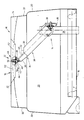
- the single figure shows a container 10 with a filling device 12, which is essentially composed of an entry conveyor 14 and a distribution device 16.
- the container 10 has a bottom 18 and is surrounded by walls 20 which form a common upper edge 22.
- the filling device 12 which is designed in accordance with the following explanations, serves to distribute material supplied by the entry conveyor 14 in the container 10 in such a way that its surface, when poured, approximately coincides with a plane running through the upper edge 22. In practice, filling up to a line labeled 24 will probably be achieved.
- the entry conveyor 14 is composed of a lower and an upper section 26 and 28.
- the entry conveyor 14 is provided with a tubular housing 30 and a conveyor element 32 rotating coaxially therein and designed as a screw.
- the conveying element 32 is driven via a drive wheel 33 designed as a belt or chain wheel and an angular gear 35.
- the drive wheel 33 simultaneously acts on a drive wheel of the paddle elevator, not shown, in the lower section 26.
- the housing 30 extends at an angle of approximately 45 ° to the horizontal and runs through an outlet 34 near the intersection of the horizontal diagonals of the container 10 out.
- the housing 30 can additionally, without being shown, be supported with struts in the container 10.
- the housing 30 contains a frame 36 which extends axially beyond the housing 30, is angled at the end and holds a bearing 38 for the rotatable reception of a shaft 40 of the conveying element 32.
- the shaft 40 is connected to a gearwheel 42 on its area projecting beyond the bearing 38.
- the gear 42 is part of an angular gear 44, which is housed in a gear housing 46 and screwed to the frame 36.
- the angular gears 35, 44 are drawn in vertical section for a better overview, but in reality are enclosed in sealed housings.
- the distribution device 16 essentially consists of a distribution element 48 designed as a rotor with a rotor shaft 50 and vanes 52 extending vertically downwards.
- the diameter of the distribution element 48 with the wings 52 is approximately one third of the width of the container 10.
- the distribution element 48 always remains in the same position and moves its wings 52 in a substantially horizontal plane.
- the rotor shaft 50 extends essentially vertically and is connected in a rotationally fixed manner at its lower end region to a gearwheel 54 of the angular gear 44 which meshes with the gearwheel 42. In its upper end region, the rotor shaft 50 is provided with the diametrically extending vanes 52.
- the distribution element 48 with the wings 52 is then driven by the chain or belt wheel 33, via the angular gear 35, the conveying element 32, the gearwheels 42, 54 in the angular gear 44 and the rotor shaft 50. Accordingly, the paddle elevator, the conveying element 32 and the distribution element 48 together, dependent on one another and driven in series from a single drive input, namely the chain or belt wheel 33.
- Other drive options are to separate each of these elements, e.g. B. by means of a hydraulic motor.
- the function of the filling device 12 according to the invention is as follows as described above.
- the container 10 is empty except for the bottom 18.
- the paddle elevator conveys conveyed goods to the conveying element 32 into the upper section 28.
- the conveyed goods are conveyed by means of the conveying element 32 fed to the outlet 34, where - depending on the throwing force of the conveying element 32 - it is thrown more or less into the movement circle of the wings 52.
- Portion is thrown into the remotest corners of the container 10 and against the walls 20; the portion not covered by the vanes 52 falls slightly scattered downward and fills the central region of the container 10.
- the distributing element 48 moves it away from the outlet 34 into the edge zones, thus eliminating the dynamic pressure in this area and relieving the weight of the upper section 28.
- a distribution of the material to be conveyed still takes place, and the build-up of a pouring cone is prevented even if the blades 52 are already rotating in the material to be conveyed; in this case, the container 10 has already almost reached its maximum capacity.
- the vanes 52 are either resilient in themselves or are attached to the rotor shaft 50 so that they can wrap around the rotor shaft 50 or can lag in the circumferential direction if the delivery torque is too high when the container 10 is full.
Landscapes
- Engineering & Computer Science (AREA)
- Mechanical Engineering (AREA)
- Life Sciences & Earth Sciences (AREA)
- Environmental Sciences (AREA)
- Filling Or Emptying Of Bunkers, Hoppers, And Tanks (AREA)
- Basic Packing Technique (AREA)
Applications Claiming Priority (2)
| Application Number | Priority Date | Filing Date | Title |
|---|---|---|---|
| DE19893911228 DE3911228C1 (enExample) | 1989-04-07 | 1989-04-07 | |
| DE3911228 | 1989-04-07 |
Publications (1)
| Publication Number | Publication Date |
|---|---|
| EP0391309A1 true EP0391309A1 (de) | 1990-10-10 |
Family
ID=6378038
Family Applications (1)
| Application Number | Title | Priority Date | Filing Date |
|---|---|---|---|
| EP90106283A Ceased EP0391309A1 (de) | 1989-04-07 | 1990-04-02 | Befüllvorrichtung für einen Behälter |
Country Status (2)
| Country | Link |
|---|---|
| EP (1) | EP0391309A1 (enExample) |
| DE (1) | DE3911228C1 (enExample) |
Cited By (3)
| Publication number | Priority date | Publication date | Assignee | Title |
|---|---|---|---|---|
| AT12775U1 (de) * | 2011-02-07 | 2012-11-15 | Bulcotech Gmbh | Vorrichtung für das befüllen eines lageraums mit granularem material |
| AT17042U1 (de) * | 2020-02-17 | 2021-03-15 | Hargassner Gmbh | Vorrichtung zum Befüllen eines Lagerraumes mit stückeligem Brennstoff |
| US11310962B2 (en) * | 2019-04-10 | 2022-04-26 | Claas Selbstfahrende Erntemaschinen Gmbh | Harvesting machine and swivel conveyor screw therefor |
Families Citing this family (1)
| Publication number | Priority date | Publication date | Assignee | Title |
|---|---|---|---|---|
| CN113245012A (zh) * | 2020-10-27 | 2021-08-13 | 赣州市倞华菲尔雪食品有限公司 | 一种脐橙酥加工用粉碎装置及作业方法 |
Citations (2)
| Publication number | Priority date | Publication date | Assignee | Title |
|---|---|---|---|---|
| US2770354A (en) * | 1954-01-27 | 1956-11-13 | Chicago Stock Yards Compost Co | Distributor fan composter |
| US3490619A (en) * | 1968-09-11 | 1970-01-20 | Int Salt Co | Load leveler |
Family Cites Families (3)
| Publication number | Priority date | Publication date | Assignee | Title |
|---|---|---|---|---|
| DE1101280B (de) * | 1959-07-01 | 1961-03-02 | Demag Ag | Vorrichtung zum Speichern von Schuettgut |
| NL6917700A (enExample) * | 1969-11-25 | 1971-05-27 | ||
| DE2703329C3 (de) * | 1977-01-27 | 1981-04-16 | Gebrüder Weiss KG, 6340 Dillenburg | Anordnung zum niveaugleichen Auffüllen von senkrechtstehenden Behältern |
-
1989
- 1989-04-07 DE DE19893911228 patent/DE3911228C1/de not_active Expired - Lifetime
-
1990
- 1990-04-02 EP EP90106283A patent/EP0391309A1/de not_active Ceased
Patent Citations (2)
| Publication number | Priority date | Publication date | Assignee | Title |
|---|---|---|---|---|
| US2770354A (en) * | 1954-01-27 | 1956-11-13 | Chicago Stock Yards Compost Co | Distributor fan composter |
| US3490619A (en) * | 1968-09-11 | 1970-01-20 | Int Salt Co | Load leveler |
Cited By (3)
| Publication number | Priority date | Publication date | Assignee | Title |
|---|---|---|---|---|
| AT12775U1 (de) * | 2011-02-07 | 2012-11-15 | Bulcotech Gmbh | Vorrichtung für das befüllen eines lageraums mit granularem material |
| US11310962B2 (en) * | 2019-04-10 | 2022-04-26 | Claas Selbstfahrende Erntemaschinen Gmbh | Harvesting machine and swivel conveyor screw therefor |
| AT17042U1 (de) * | 2020-02-17 | 2021-03-15 | Hargassner Gmbh | Vorrichtung zum Befüllen eines Lagerraumes mit stückeligem Brennstoff |
Also Published As
| Publication number | Publication date |
|---|---|
| DE3911228C1 (enExample) | 1990-10-04 |
Similar Documents
| Publication | Publication Date | Title |
|---|---|---|
| DE2709309C3 (de) | Vorrichtung zum Austragen von fließfähigem Gut | |
| DE2353025A1 (de) | Vorrichtung zum entleeren des kornsammelbehaelters eines maehdreschers oder dergl | |
| EP1951416B1 (de) | Vorrichtung zur herstellung einer mischung aus verschiedenen schüttgutkomponenten | |
| WO2013011065A2 (de) | Mobile brechanlage sowie mobile brechanlagenanordnung | |
| DE3390175C2 (enExample) | ||
| DE102010031648A1 (de) | Beschickungsvorrichtung für Schüttgut | |
| DE2147280B2 (de) | Vorrichtung zum Mischen von schüttbarem Erntegut | |
| EP0391309A1 (de) | Befüllvorrichtung für einen Behälter | |
| EP3488931B1 (de) | Vorrichtung zum trennen von materialgemischen | |
| DE1940714A1 (de) | Vorrichtung zum Austragen von Schuettguetern aus Silos | |
| DE2318560C2 (de) | Silo zum Speichern und Entnehmen von schüttfähigem, jedoch schwerfließendem Gut | |
| DE3207751C2 (de) | Schaufelrad-Rückladegerät für Schüttguthalden | |
| DE4230247A1 (de) | Füllvorrichtung für insbesondere Ventilsäcke | |
| DE1941831A1 (de) | Mischmaschine | |
| DE4300548C1 (de) | Gerät zur Herstellung und Aufrechterhaltung einer vollständigen Mischung eines aus festen und flüssigen Bestandteilen bestehenden plastischen Produkts | |
| AT393259B (de) | Verfahren und vorrichtung zum befuellen von schuettgutbehaeltern mit einer schurre | |
| DE29604743U1 (de) | Mischmaschine für Mörtel, Beton o.dgl. | |
| DE3429023C2 (enExample) | ||
| AT398443B (de) | Winterdienst-streugerät mit förderschnecke | |
| DE2808234A1 (de) | Einrichtung zum zufuehren von material und fuellen senkrecht angeordneter foerderschnecken | |
| DE2605313A1 (de) | Vorrichtung zum mechanischen auflockern und zufuehren von schwerfliessenden schuettguetern | |
| DE2449818A1 (de) | Austragevorrichtung fuer einen aufrechtstehenden silo | |
| AT380453B (de) | Vorrichtung fuer kreisrunde silos zum verteilen und gegebenenfalls entnehmen der silage | |
| DE949816C (de) | Maschine zum Einschaufeln, Befoerdern und Einsacken von Massenguetern, wie Kohle | |
| DE2734921C3 (de) | Silo für nicht rieselfähiges Gut |
Legal Events
| Date | Code | Title | Description |
|---|---|---|---|
| PUAI | Public reference made under article 153(3) epc to a published international application that has entered the european phase |
Free format text: ORIGINAL CODE: 0009012 |
|
| AK | Designated contracting states |
Kind code of ref document: A1 Designated state(s): BE DE FR GB IT |
|
| 17P | Request for examination filed |
Effective date: 19901208 |
|
| 17Q | First examination report despatched |
Effective date: 19911002 |
|
| STAA | Information on the status of an ep patent application or granted ep patent |
Free format text: STATUS: THE APPLICATION HAS BEEN REFUSED |
|
| 18R | Application refused |
Effective date: 19930423 |