EP0387505B1 - Chaussure, notamment chaussure de sport ou chaussure de rééducation - Google Patents
Chaussure, notamment chaussure de sport ou chaussure de rééducation Download PDFInfo
- Publication number
- EP0387505B1 EP0387505B1 EP90101536A EP90101536A EP0387505B1 EP 0387505 B1 EP0387505 B1 EP 0387505B1 EP 90101536 A EP90101536 A EP 90101536A EP 90101536 A EP90101536 A EP 90101536A EP 0387505 B1 EP0387505 B1 EP 0387505B1
- Authority
- EP
- European Patent Office
- Prior art keywords
- shoe
- honeycomb
- honeycomb body
- sole
- cells
- Prior art date
- Legal status (The legal status is an assumption and is not a legal conclusion. Google has not performed a legal analysis and makes no representation as to the accuracy of the status listed.)
- Expired - Lifetime
Links
Images

Classifications
-
- A—HUMAN NECESSITIES
- A43—FOOTWEAR
- A43B—CHARACTERISTIC FEATURES OF FOOTWEAR; PARTS OF FOOTWEAR
- A43B7/00—Footwear with health or hygienic arrangements
- A43B7/14—Footwear with health or hygienic arrangements with foot-supporting parts
- A43B7/1405—Footwear with health or hygienic arrangements with foot-supporting parts with pads or holes on one or more locations, or having an anatomical or curved form
- A43B7/1415—Footwear with health or hygienic arrangements with foot-supporting parts with pads or holes on one or more locations, or having an anatomical or curved form characterised by the location under the foot
- A43B7/1425—Footwear with health or hygienic arrangements with foot-supporting parts with pads or holes on one or more locations, or having an anatomical or curved form characterised by the location under the foot situated under the ball of the foot, i.e. the joint between the first metatarsal and first phalange
-
- A—HUMAN NECESSITIES
- A43—FOOTWEAR
- A43B—CHARACTERISTIC FEATURES OF FOOTWEAR; PARTS OF FOOTWEAR
- A43B1/00—Footwear characterised by the material
- A43B1/0009—Footwear characterised by the material made at least partially of alveolar or honeycomb material
-
- A—HUMAN NECESSITIES
- A43—FOOTWEAR
- A43B—CHARACTERISTIC FEATURES OF FOOTWEAR; PARTS OF FOOTWEAR
- A43B13/00—Soles; Sole-and-heel integral units
- A43B13/14—Soles; Sole-and-heel integral units characterised by the constructive form
- A43B13/18—Resilient soles
- A43B13/20—Pneumatic soles filled with a compressible fluid, e.g. air, gas
-
- A—HUMAN NECESSITIES
- A43—FOOTWEAR
- A43B—CHARACTERISTIC FEATURES OF FOOTWEAR; PARTS OF FOOTWEAR
- A43B13/00—Soles; Sole-and-heel integral units
- A43B13/28—Soles; Sole-and-heel integral units characterised by their attachment, also attachment of combined soles and heels
-
- A—HUMAN NECESSITIES
- A43—FOOTWEAR
- A43B—CHARACTERISTIC FEATURES OF FOOTWEAR; PARTS OF FOOTWEAR
- A43B17/00—Insoles for insertion, e.g. footbeds or inlays, for attachment to the shoe after the upper has been joined
- A43B17/02—Insoles for insertion, e.g. footbeds or inlays, for attachment to the shoe after the upper has been joined wedge-like or resilient
- A43B17/03—Insoles for insertion, e.g. footbeds or inlays, for attachment to the shoe after the upper has been joined wedge-like or resilient filled with a gas, e.g. air
-
- A—HUMAN NECESSITIES
- A43—FOOTWEAR
- A43B—CHARACTERISTIC FEATURES OF FOOTWEAR; PARTS OF FOOTWEAR
- A43B23/00—Uppers; Boot legs; Stiffeners; Other single parts of footwear
- A43B23/08—Heel stiffeners; Toe stiffeners
-
- A—HUMAN NECESSITIES
- A43—FOOTWEAR
- A43B—CHARACTERISTIC FEATURES OF FOOTWEAR; PARTS OF FOOTWEAR
- A43B7/00—Footwear with health or hygienic arrangements
- A43B7/14—Footwear with health or hygienic arrangements with foot-supporting parts
- A43B7/1405—Footwear with health or hygienic arrangements with foot-supporting parts with pads or holes on one or more locations, or having an anatomical or curved form
- A43B7/1415—Footwear with health or hygienic arrangements with foot-supporting parts with pads or holes on one or more locations, or having an anatomical or curved form characterised by the location under the foot
- A43B7/144—Footwear with health or hygienic arrangements with foot-supporting parts with pads or holes on one or more locations, or having an anatomical or curved form characterised by the location under the foot situated under the heel, i.e. the calcaneus bone
-
- A—HUMAN NECESSITIES
- A43—FOOTWEAR
- A43B—CHARACTERISTIC FEATURES OF FOOTWEAR; PARTS OF FOOTWEAR
- A43B7/00—Footwear with health or hygienic arrangements
- A43B7/14—Footwear with health or hygienic arrangements with foot-supporting parts
- A43B7/1405—Footwear with health or hygienic arrangements with foot-supporting parts with pads or holes on one or more locations, or having an anatomical or curved form
- A43B7/1415—Footwear with health or hygienic arrangements with foot-supporting parts with pads or holes on one or more locations, or having an anatomical or curved form characterised by the location under the foot
- A43B7/1445—Footwear with health or hygienic arrangements with foot-supporting parts with pads or holes on one or more locations, or having an anatomical or curved form characterised by the location under the foot situated under the midfoot, i.e. the second, third or fourth metatarsal
-
- A—HUMAN NECESSITIES
- A43—FOOTWEAR
- A43B—CHARACTERISTIC FEATURES OF FOOTWEAR; PARTS OF FOOTWEAR
- A43B7/00—Footwear with health or hygienic arrangements
- A43B7/14—Footwear with health or hygienic arrangements with foot-supporting parts
- A43B7/1405—Footwear with health or hygienic arrangements with foot-supporting parts with pads or holes on one or more locations, or having an anatomical or curved form
- A43B7/1415—Footwear with health or hygienic arrangements with foot-supporting parts with pads or holes on one or more locations, or having an anatomical or curved form characterised by the location under the foot
- A43B7/145—Footwear with health or hygienic arrangements with foot-supporting parts with pads or holes on one or more locations, or having an anatomical or curved form characterised by the location under the foot situated under the toes, i.e. the phalanges
-
- A—HUMAN NECESSITIES
- A43—FOOTWEAR
- A43B—CHARACTERISTIC FEATURES OF FOOTWEAR; PARTS OF FOOTWEAR
- A43B7/00—Footwear with health or hygienic arrangements
- A43B7/14—Footwear with health or hygienic arrangements with foot-supporting parts
- A43B7/1405—Footwear with health or hygienic arrangements with foot-supporting parts with pads or holes on one or more locations, or having an anatomical or curved form
- A43B7/1455—Footwear with health or hygienic arrangements with foot-supporting parts with pads or holes on one or more locations, or having an anatomical or curved form with special properties
- A43B7/1464—Footwear with health or hygienic arrangements with foot-supporting parts with pads or holes on one or more locations, or having an anatomical or curved form with special properties with adjustable pads to allow custom fit
-
- A—HUMAN NECESSITIES
- A43—FOOTWEAR
- A43B—CHARACTERISTIC FEATURES OF FOOTWEAR; PARTS OF FOOTWEAR
- A43B7/00—Footwear with health or hygienic arrangements
- A43B7/14—Footwear with health or hygienic arrangements with foot-supporting parts
- A43B7/1405—Footwear with health or hygienic arrangements with foot-supporting parts with pads or holes on one or more locations, or having an anatomical or curved form
- A43B7/1475—Footwear with health or hygienic arrangements with foot-supporting parts with pads or holes on one or more locations, or having an anatomical or curved form characterised by the type of support
- A43B7/148—Recesses or holes filled with supports or pads
-
- A—HUMAN NECESSITIES
- A43—FOOTWEAR
- A43B—CHARACTERISTIC FEATURES OF FOOTWEAR; PARTS OF FOOTWEAR
- A43B7/00—Footwear with health or hygienic arrangements
- A43B7/14—Footwear with health or hygienic arrangements with foot-supporting parts
- A43B7/22—Footwear with health or hygienic arrangements with foot-supporting parts with fixed flat-foot insertions, metatarsal supports, ankle flaps or the like
Definitions
- the present invention relates to a shoe, in particular a sports shoe or a rehabilitation shoe, according to the preamble of claim 1.
- an insole for a shoe which has a honeycomb structure.
- the top of this insole is made of air-permeable material and the bottom of a thin lamination.
- the honeycomb cells which are attached between the foamed upholstery (top side) and the thin lamination, are at least partially open, since the honeycomb body is made of corrugated or meandering bands glued together on the walls and then stretched, so that honeycomb cells of elongated rectangular shape. Because of the open edge honeycomb cells, such honeycomb bodies have a strongly decreasing damping towards the edge, so that the restoring force of such a honeycomb body in the edge regions also tends to almost zero.
- a shoe in particular a sports shoe or rehabilitation shoe, with a honeycomb body made of elastic, compressible material is to be improved in such a way that on the one hand the cushioning and on the other hand the restoring force of the shoe sole and thus the energy gain after the pressure relief of the shoe sole are significantly increased.
- honeycomb cells closed in the edge region of the finished molded body significantly increase the restoring force in this edge region of the honeycomb body, so that the inner region of the damping and restoring force-producing honeycomb body is even softer than this edge region. This ensures the desired high energy gain, especially in the edge area of the shoe sole, which also provides protection against the dreaded overpronation or oversupination.
- a very favorable spring characteristic with a higher restoring force is obtained in all honeycomb cells by the honeycomb cells which are sealed gas-tight or at least approximately gas-tight at the top and bottom. This is especially true in the event that the individual Honeycomb cells are filled with a gas pressure that is significantly higher than the atmospheric pressure.
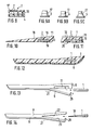
- Fig. 1, 1 denotes a honeycomb body made of an injection molded part, which consists of elastic, compressible material, in particular plastic, such as polyurethane, polyolefin, polyethylene, polypropylene, polybutane, polyamide, ethylene-vinyl acetate or the like.
- the aforementioned plastics are preferably compact, non-foamed plastics.
- the individual honeycomb cells 2, 2 ' preferably have a polygonal cross section, preferably a hexagonal cross section. However, honeycomb cells 2, 2 'with, for example, circular, elliptical or other rounded cross sections are also within the scope of the invention.
- the honeycomb body 1 has a peripheral edge 3, which seals the edge cells 2 'of the honeycomb cells 2 from the outside, in particular gas-tight.
- the honeycomb body 1 is made, for example, according to the representation of the left half of FIG. 2 so that first the two sides of the honeycomb cells 2 are open at the top and bottom and the top and bottom 2a, 2b, each with a cover element 4 gas-tight or in any case are largely sealed gas-tight.
- the cover elements 4 preferably consist of film or plate material and preferably have one Thickness from 0.1 to 1.5 mm. They are in particular connected to the wall surfaces of the honeycomb cells or edge cells 2, 2 'by an adhesive or welding process.
- the honeycomb body 1 can be produced, for example, by injection molding in such a way that one, for example the upper side or surface of the honeycomb cells 2 or 2 'is closed. It is then only necessary to close the underside of the honeycomb cells 2, 2 'with a cover element 4.
- the thickness or height of a honeycomb body 1 is preferably 0.3 cm to 1.5 cm, in particular 0.5 cm to 1.0 cm, and is preferably constant over the entire extent of the honeycomb body 1. However, it can also be tapered in the direction of the tip of the shoe sole, for example corresponding to a heel wedge.
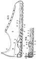
- the honeycomb body 1 is provided as an insert in a shoe sole 5, which is preferably designed as a shell sole, in the central region 6 of the heel bone 7.
- the honeycomb body 1 is therefore laterally everywhere at least 1 cm to 2 cm away from the circumferential outer edge 15 of the shoe sole 5.
- 5 fixing elements in the form of ribs or the like can be provided within the shoe sole.
- the attachment of the honeycomb body 1 shown in FIG. 3 in the area 6 of the heel bone 7 offers the advantage that the heel bone 7 directly or indirectly engages with the honeycomb body 1, which leads to a good damping effect and to the desired energy gain (springback) after Pressure relief of the shoe sole leads.
- the shoe sole 5 consists of an abrasion-resistant outsole 8, a cushioning midsole 9 and an upper or inner sole 10.
- the honeycomb body 1 is provided in a recess 11 in the midsole 9.
- a honeycomb body 1 according to the invention can also be located in the area 12 (dash-dotted line) of the big toe ball or in the area 13 (dashed line) of the toe ball or also in the area 14 (dotted line) of the forefoot Embodiment can be provided, as is illustrated in more detail with reference to FIG. 3.
- good damping and resilience properties are obtained in these sole areas, which is due both to the honeycomb structure and to the gas suspension of the gas-tight or largely gas-tight honeycomb cells 2, 2 '.
- the gas pressure in the honeycomb cells 2, 2 ' can be greater than the atmospheric pressure and therefore, for example, between 1000 hPa and 3000 hPa, in particular 2500 hPa.
- the damping and resetting properties of the honeycomb body 1 can be determined or co-determined by the thickness of the honeycomb walls 16.
- the cover element (s) 4 can be designed as a film, plate or cover. As can be seen from FIG. 9, when the cover elements 4 are designed as lids, they can be provided with projections 17 provided on the inside, the projections 17 being shaped in the same way as the honeycomb structure of the honeycomb body 1 and engaging in the honeycomb cells 2, 2 '. By pressing such a "cover” onto the open side (s) of the honeycomb body 1, it is closed in a gas-tight manner, at least in most cases gas-tight, by latching and / or jamming. In addition, the cover element 4 can be glued or welded to the honeycomb structure.
- the projections 17 are preferably inclined or tapered upwards, as can be seen in FIGS. 9 a to 9 c, or the projections 17 are slightly conical on the foot in order to enable a gas-tight seal in particular.
- the height of the projections 17 is preferably between approximately 1 mm to approximately 4 mm.
- the honeycomb body 1 can be accommodated within this heel wedge 18.
- the honeycomb body 1 is accommodated in a recess 11 in a heel wedge 18 and the recess 11 is additionally covered at the bottom, for example, by a cover plate 19 made of elastic material with a Shore hardness between 40 and 80 Shore-A.
- the cover plate 19 is preferably inserted, in particular clamped and / or glued.
- a honeycomb body 1 into a heel wedge 18 or into another sole part, for example into the midsole 9 can also be inserted from the side into a slot 20 or into a corresponding lateral opening, as shown in FIG. 11.
- the slot 20 or the lateral opening is again closed to the outside with a cover plate 19 or with a cover strip.
- the honeycomb body 1 can preferably be completely surrounded by the material of the heel wedge 18 or the midsole 9, as shown in FIG. This is preferably done by a reshaping process, for example by casting or injection molding, in which the honeycomb body 1 is placed in a hollow mold and surrounded by the material to be overmolded or overmolded.
- a shoe sole 5 can be used whose outsole 8 can be folded down, for example from the joint region 21 to the heel, and again with the rest of the sole part or directly with the shaft part or is firmly connected to the heel counter.
- the midsole 9 is provided with a recess 11 into which the honeycomb body 1 can be inserted. After inserting the honeycomb body 1, the outsole part folded down is again folded up and fastened to the rest of the shoe part or to the heel.
- FIG. 14 A similar embodiment with a divided midsole 9 can be seen in FIG. 14. There, a heel wedge 18 with a honeycomb body 1 or a honeycomb body 1 designed as a heel wedge is inserted between the parting planes 22 and 23 of the midsole 9.
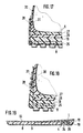
- Fig. 15 there is a shoe, in particular a sports shoe or a shoe for medical purposes, preferably for rehabilitation purposes. Although only a low shoe is shown, this shoe can of course also be designed as a boot or ankle boot.
- the shoe 24 has a sole which is composed of an outsole 8, optionally with a damping insert 25 firmly connected to it, and an intermediate sole 9 consisting of a layer 26 and a second layer 27.
- the midsole 9 can also be made in one part or more than two parts.
- Outsole 8, cushioning insert 25 and midsole 9 consist of the possible and customary, resilient materials, in particular of volume-compressible materials.
- the sole is designed such that the outsole 8 can be separated from the midsole 9 over a large part of its longitudinal extent, but at least approximately from the joint region 21 to the end of the shoe, that is to the heel.
- Midsole 9 and outsole 8 or their cushioning insert 25 are therefore not glued to one another in this area or otherwise permanently connected to one another.
- the outsole 8 is fastened in the separating area by means of fastening means 28 attached to it, which can be positively or positively connected to corresponding counterparts 31 attached to the midsole 9 and / or to the upper material or shaft 20 and / or also to a heel cap 30.
- the releasable connecting parts are each designed so that a releasable non-positive or positive, mechanically safe connection of the separable part of the outsole 8 with the rest of the shoe is ensured.
- the detachable connection takes place according to the 15 and 16 by as upwardly projecting, designed as elastically bendable tabs fasteners which are arranged distributed on the edge of the outsole 8.
- the entire edge of the outsole 8 can also protrude upward in the form of a shell.
- one or more rows of at least two holes 32 arranged one above the other are provided, into which counterparts 31 of the midsole 9 designed as pins, for example as plug-in and / or locking pins, can be inserted, buttoned in or locked in some other way be.
- the pins 31 can be designed in the manner of nails and inserted or molded into the midsole 9 or molded onto them, that is to say in the latter case they consist of a single component with the midsole 9. 15, the locking pins 31 are inserted into the lowermost holes 32.
- the outsole 8 lies here with its damping insert 25 directly on the midsole 9.
- FIG. 16 shows an embodiment in which the locking pins 31 are inserted in the central holes 32. This creates a wedge-shaped intermediate space 33 between the outsole 8 or its cushioning insert 25 and the midsole 9. In this intermediate space 33, a wedge-shaped honeycomb body 1 or heel wedge 18 with a honeycomb body 1 can be inserted or used interchangeably (FIGS. 16, 17 and 18).
- the intermediate space 33 widens and a correspondingly thicker heel wedge 18 and / or honeycomb body 1 can be used.
- the heel wedge 18 and / or the honeycomb body 1 and the midsole 9 advantageously consist of elastic, in particular foamed, preferably volume-compressible plastics, preferably based on ethylene vinyl acetate.
- connecting elements can be used as fastening means 28 and counterparts 31.
- fastening means 28 can be used as fastening means 28 and counterparts 31.
- aids such as, for example, pins or bolts can be inserted or screwed through the holes 32 into the midsole 9.
- toothings which can be locked into one another can also be provided on the tab 28 or on the edge of the outsole 8 and on a heel cap 30, as shown in FIG. 17. The catch is released by pulling the tab off to the side.
- a lever lock can also be provided as the fastening means 28 and counterpart 31.
- the type of connecting elements that can be used is not limited to the exemplary embodiments shown and described.
- a "wedge heel" of different heights and / or damping can be obtained in a variety of ways.
- the Honeycomb body 1 can in particular also be chosen so that the shoe 24 is adapted to the weight of the person wearing it.
- honeycomb body 1 It has proven expedient to choose a hardness of the honeycomb body 1 of approximately 25 Shore A, up to 70 kg of approximately 35 Shore A and up to 80 kg and more of approximately 45 Shore A for a person weight of up to 60 kg .
- a window 34 can be provided in the outsole 8 below the central heel area 6, in which a honeycomb body 1 is located in the midsole 9 or in a heel wedge 18.
- the honeycomb cover element 4 or a cover plate 19 is hereby accessible from the outside and can be brought into direct contact with the ground.
- the cover element 4 or the cover plate 19 consist of abrasion-resistant, elastic material, for example of non-foamed polyurethane, and preferably have a Shore A hardness between 20 and 70.
- the underside 35 of the cover element 4 or the cover plate 19 can be arranged slightly recessed inwards in the outsole 8, for example between 1 mm and 3 mm. This provides better damping.
- cover element 4 or the cover plate 19 visible through the window 34 can consist of transparent or at least translucent material, so that the honeycomb structure is recognizable or can still be recognized. This enables the person skilled in the art to determine the damping character and the restoring force of the honeycomb body used, for example on the basis of a table.
- honeycomb cells 2, 2 is not limited to the generally known hexagonal honeycomb shape shown. Rather, many possibilities of modifications, starting with triangular or more than hexagonal honeycombs, also round or oval honeycombs can be used and used accordingly.
- the honeycomb body 1 already receives its final shape as an injection, injection molding or casting part during the injection, injection molding or casting process, the honeycomb cells 2, 2 'on the circumference or edge 3 of the honeycomb body 1 preferably already through the injection, injection molding or casting process are sealed gas-tight.
- the large flat surfaces of the honeycomb body 1 are sealed or largely sealed against gas leakage on one or both sides by means of gas-tight foils, lids or other covering elements, in particular made of plastic, by means of material, positive or non-positive connections.
- the honeycomb body 1 is designed as a final shaped body in its dimensions also applies to a modified embodiment, according to which only a single, uniform shaped body is provided which corresponds at least approximately to the shape or contour of the outsole 8 and is preferably connected to the entire surface.
- the uniform, honeycomb shaped body practically forms the midsole or replaces a separate midsole between the actual outsole and the shoe insole.
- the honeycomb cells 2, 2 ' have a spacing of opposing walls in the range of 3 mm to 15 mm in the case of a polygonal configuration and a diameter or an extension of the large ellipse axis of 3 to 15 mm in the case of a round or elliptical configuration.
Landscapes
- Health & Medical Sciences (AREA)
- Epidemiology (AREA)
- General Health & Medical Sciences (AREA)
- Public Health (AREA)
- Footwear And Its Accessory, Manufacturing Method And Apparatuses (AREA)
Claims (27)
- Chaussure, notamment chaussure de sport ou de rééducation, comportant une semelle avec au moins un insert en une matière compressible élastique, en forme de corps alvéolaire, les axes centraux des cellules alvéolaires remplies de gaz étant au moins pratiquement perpendiculaires au plan de la semelle, chaussure caractérisée en ce que le corps alvéolaire (1) est une pièce moulée aux dimensions définitives, les cellules alvéolaires (2, 2') à la périphérie ou au bord (3) du corps alvéolaire (1) étant fermées de manière étanche au gaz, les ouvertures supérieure et inférieure des cellules alvéolaires (2a, 2b) étant fermées de manière étanche au gaz ou, dans le cas d'éventuelles fentes aux bords entre les cellules alvéolaires (2, 2') et les surfaces (4) recouvrant la face supérieure et la face inférieure, celles-ci sont fermées pour être au moins sensiblement étanches au gaz et en ce que le ou les corps alvéolaires (1) sont prévus dans la semelle enveloppante (5) et y sont fixés ou reliés à celle-ci sous forme de corps en une seule pièce, correspondant au moins approximativement à la forme ou au contour de la semelle d'usure (8).
- Chaussure selon la revendication 1, caractérisée en ce que le corps alvéolaire (1) est prévu dans la zone centrale (6) en-dessous de l'os (7) du talon.
- Chaussure selon la revendication 1, caractérisée par un autre corps alvéolaire (1) dans la zone (12) de la paume du gros orteil ou dans la zone (13) de la paume des doigts de pied ou dans la zone (14) de l'avant du pied.
- Chaussure selon l'une des revendications 1 à 3, caractérisée en ce que l'épaisseur ou la hauteur du corps alvéolaire (1) est constante ou pratiquement constante.
- Chaussure selon l'une des revendications 1 à 4, caractérisée en ce que l'épaisseur des parois d'alvéoles (16) est différente dans différentes parties du corps alvéolaire (1).
- Chaussure selon l'une des revendications 1 à 5, caractérisée en ce que les parois (16) des cellules alvéolaires (2, 2') sont en forme de tronc de cône.
- Chaussure selon l'une des revendications 1 à 6, caractérisée en ce que le corps alvéolaire (1) se compose d'une pièce injectée ouverte sur les deux extrémités des cellules alvéolaires (2, 2'), la fermeture par le dessus et par le dessous se faisant de manière étanche ou pratiquement étanche au gaz par chaque fois un élément de recouvrement (4).
- Chaussure selon l'une des revendications 1 à 6, caractérisée en ce que le corps alvéolaire (1) se compose d'une pièce injectée dont seulement une extrémité des cellules alvéolaires (2, 2') est ouverte, et en ce que l'extrémité ouverte des cellules (2, 2') est fermée de manière étanche au gaz ou au moins pratiquement étanche au gaz par un élément de recouvrement (4).
- Chaussure selon la revendication 7 ou 8, caractérisée en ce que l'élément de recouvrement (4) est en forme de couvercle avec des saillies (17) correspondant aux surfaces intérieures du corps alvéolaire (1), ces saillies pouvant s'accrocher et/ou se coincer aux surfaces d'alvéoles du corps alvéolaire (1) sous l'effet de la pression, d'une manière étanche ou pratiquement étanche au gaz.
- Chaussure selon la revendication 9, caractérisée en ce que la hauteur des saillies (17) est de l'ordre de 1 mm à 4 mm.
- Chaussure selon la revendication 9, caractérisée en ce que les saillies (17) sont au moins partiellement légèrement coniques.
- Chaussure selon l'une des revendications 1 à 11, caractérisée en ce que la semelle (5) se compose d'une semelle d'usure (8), d'une semelle intermédiaire (9) et d'une première de montage (10) et en ce que le corps alvéolaire (1) est logé dans la semelle intermédiaire (9).
- Chaussure selon l'une des revendications 1 à 12, caractérisée en ce que la semelle (5) comporte un coin de semelle (18) et le corps alvéolaire (1) est prévu dans le coin de semelle (18).
- Chaussure selon l'une des revendications 1 à 13, caractérisée en ce que le corps alvéolaire (1) est logé dans une cavité (11) de la semelle intermédiaire (9) ou du coin de talon (18).
- Chaussure selon la revendication 14, caractérisée en ce que la cavité (11) est ouverte vers le bas.
- Chaussure selon la revendication 14, caractérisée en ce que la cavité (11) est au moins ouverture latéralement, d'un côté, ou comporte une fente (20) et le corps alvéolaire (1) est le cas échéant placé dans l'ouverture latérale et/ou dans la fente (20).
- Chaussure selon la revendication 15 ou 16, caractérisée en ce que la cavité (11) est fermée par une plaque de recouvrement (19).
- Chaussure selon la revendication 15 ou 16, caractérisée en ce que le corps alvéolaire (1) est entouré de tous côtés par la matière de la semelle intermédiaire (9) ou du coin de semelle (18).
- Chaussure selon la revendication 18, caractérisée en ce que le corps alvéolaire (1) est injecté ou entouré de la matière de la semelle intermédiaire (9) ou du coin de semelle (18).
- Chaussure selon l'une des revendications 1 à 19, caractérisée en ce que la semelle d'usure (8) est fixée sensiblement à partir de la zone d'articulation (21), vers l'arrière vers le talon et le cas échéant avec la ou une partie de la semelle intermédiaire (9) en pouvant s'écarter vers le bas, à la matière de la partie restante de la semelle ou de la tige et avec le renfort de talon (30) d'une chaussure (24) et en ce que le corps alvéolaire (1) se place uniquement dans une cavité (11) de la semelle intermédiaire (9) et/ou du coin de talon (18) ou avec une pièce intermédiaire (par exemple un coin de talon 18) entre les plans de séparation (22, 23).
- Chaussure selon la revendication 20, caractérisée en ce que l'épaisseur du corps alvéolaire (1) va en diminuant vers l'avant en forme de coin, au moins dans la zone d'articulation (21).
- Chaussure selon l'une des revendications 1 à 21, caractérisée en ce que la semelle d'usure (8) comporte une fenêtre (34), au moins en-dessous du corps alvéolaire (1), prévue dans la zone de talon (6) et un élément de recouvrement (4) ou une plaque de recouvrement (19) supplémentaire en une matière élastique résistant à l'usure sont prévus par-dessous sur le corps alvéolaire (1).
- Chaussure selon la revendication 22, caractérisée en ce que la face inférieure (35) de l'élément de recouvrement (4) ou de la plaque de recouvrement (19) est en retrait dans la semelle d'usure (8).
- Chaussure selon la revendication 22 ou 23, caractérisée en ce que l'élément de recouvrement (4) inférieur ou la plaque de recouvrement (19) sont en une matière translucide ou transparente.
- Chaussure selon l'une des revendications 1 à 24, caractérisée en ce que le corps alvéolaire (1) est en une matière plastique choisie dans le groupe formé par polyéthylène, polypropylène, polybutane, polyamide, polyuréthane ou des mélanges d'au moins deux de telles matières plastiques.
- Chaussure selon la revendication 25, caractérisée en ce que la matière plastique est une matière expansée à pores fermés et possède une densité plus élevée et une dureté Shore A plus grande que la semelle intermédiaire (9) et/ou le coin de talon (18).
- Chaussure selon l'une des revendications 1 à 26, caractérisée en ce qu'à l'intérieur des cellules alvéolaires (2, 2') du corps alvéolaire (1) on a une pression de gaz comprise entre 1000 hPa - 3000 hPa.
Applications Claiming Priority (2)
| Application Number | Priority Date | Filing Date | Title |
|---|---|---|---|
| DE8901236U DE8901236U1 (fr) | 1989-02-03 | 1989-02-03 | |
| DE8901236U | 1989-02-03 |
Publications (2)
| Publication Number | Publication Date |
|---|---|
| EP0387505A1 EP0387505A1 (fr) | 1990-09-19 |
| EP0387505B1 true EP0387505B1 (fr) | 1993-07-07 |
Family
ID=6835671
Family Applications (1)
| Application Number | Title | Priority Date | Filing Date |
|---|---|---|---|
| EP90101536A Expired - Lifetime EP0387505B1 (fr) | 1989-02-03 | 1990-01-26 | Chaussure, notamment chaussure de sport ou chaussure de rééducation |
Country Status (6)
| Country | Link |
|---|---|
| EP (1) | EP0387505B1 (fr) |
| JP (1) | JPH0327603U (fr) |
| AT (1) | ATE91220T1 (fr) |
| DE (2) | DE8901236U1 (fr) |
| DK (1) | DK0387505T3 (fr) |
| ES (1) | ES2024360A6 (fr) |
Cited By (2)
| Publication number | Priority date | Publication date | Assignee | Title |
|---|---|---|---|---|
| DE20206927U1 (de) * | 2002-05-01 | 2003-09-04 | Dassler Puma Sportschuh | Dämpfungselement für einen Schuh |
| WO2005060781A1 (fr) | 2003-12-23 | 2005-07-07 | Puma Aktiengesellschaft Rudolf Dassler Sport | Chaussure |
Families Citing this family (19)
| Publication number | Priority date | Publication date | Assignee | Title |
|---|---|---|---|---|
| FR2666967A1 (fr) * | 1990-09-21 | 1992-03-27 | M2000 Comercio Representacoes | Semelle pour chaussures. |
| DE4200362C2 (de) * | 1992-01-09 | 1994-06-09 | Bauerfeind Gmbh | Einlegesohle |
| DE4202170A1 (de) * | 1992-01-27 | 1993-07-29 | Wilhelm Kaechele Gmbh Kautschu | Schuhsohle |
| WO1993023190A1 (fr) * | 1992-05-20 | 1993-11-25 | Sunkyong Industries Co., Ltd. | Panneau alveolaire ayant une elasticite amelioree |
| DE4226254A1 (de) * | 1992-08-08 | 1994-02-17 | Helmut Fritzsche | Schuhsohle mit Luftkammern im Fersenbereich |
| US5329705A (en) * | 1993-02-16 | 1994-07-19 | Royce Medical Company | Footgear with pressure relief zones |
| DE4336395A1 (de) * | 1993-10-26 | 1995-04-27 | Wilhelm Kaechele Gmbh Kautschu | Schuheinheit mit Dämpfungskörper |
| DE4339103C2 (de) * | 1993-11-16 | 1998-07-02 | Engros Schuhhaus Ag | Schuhsohle |
| DE29907844U1 (de) * | 1999-05-03 | 2000-09-14 | Dassler Puma Sportschuh | Dämpfungseinsatz für einen Schuh und Schuh mit einem derartigen Dämpfungseinsatz |
| DE29907839U1 (de) * | 1999-05-03 | 2000-09-14 | Dassler Puma Sportschuh | Schuh-Innensohle |
| JP2002191404A (ja) * | 2000-12-26 | 2002-07-09 | Daiwa Seiko Inc | 釣用履物 |
| DE202005001005U1 (de) * | 2005-01-22 | 2006-06-08 | Puma Aktiengesellschaft Rudolf Dassler Sport | Schuh, insbesondere Sportschuh |
| DE202005001006U1 (de) * | 2005-01-22 | 2006-06-01 | Puma Aktiengesellschaft Rudolf Dassler Sport | Schuh, insbesondere Sportschuh |
| DE202005012062U1 (de) * | 2005-08-01 | 2006-12-14 | Puma Aktiengesellschaft Rudolf Dassler Sport | Schuh, insbesondere Sportschuh |
| DE202005017306U1 (de) | 2005-11-05 | 2007-03-15 | Puma Aktiengesellschaft Rudolf Dassler Sport | Schuh, insbesondere Sportschuh |
| TW200810725A (en) * | 2006-08-16 | 2008-03-01 | Ya-Jing Yang | Tight-rotating device of cleaning utensil |
| JP5248823B2 (ja) * | 2007-08-30 | 2013-07-31 | 株式会社アシックス | 靴底用の緩衝パーツ並びにこのものを具えた靴 |
| DE102008016362A1 (de) * | 2008-03-29 | 2009-10-01 | Müller, Hans | Schuh-Luft-Polster-Einlage |
| US10806214B2 (en) * | 2013-03-08 | 2020-10-20 | Nike, Inc. | Footwear fluid-filled chamber having central tensile feature |
Family Cites Families (5)
| Publication number | Priority date | Publication date | Assignee | Title |
|---|---|---|---|---|
| DE2542760C3 (de) * | 1975-09-25 | 1980-08-14 | Armin A. 8522 Herzogenaurach Dassler | Sportschuh, insbesondere Tennisschuh |
| GB2122872B (en) * | 1982-06-09 | 1985-10-09 | Griplite S L | Sports shoes |
| US4485568A (en) * | 1983-03-25 | 1984-12-04 | Landi Curtis L | Insole |
| US4594799A (en) * | 1984-12-10 | 1986-06-17 | Autry Industries, Inc. | Tennis shoe construction |
| US4663865A (en) * | 1985-01-14 | 1987-05-12 | Iwo Cilicia S.A.C.I.F.I.A. | Sport shoes |
-
1989
- 1989-02-03 DE DE8901236U patent/DE8901236U1/de not_active Expired - Lifetime
-
1990
- 1990-01-26 DK DK90101536.2T patent/DK0387505T3/da active
- 1990-01-26 DE DE9090101536T patent/DE59001896D1/de not_active Expired - Fee Related
- 1990-01-26 AT AT90101536T patent/ATE91220T1/de not_active IP Right Cessation
- 1990-01-26 EP EP90101536A patent/EP0387505B1/fr not_active Expired - Lifetime
- 1990-02-02 ES ES9003182A patent/ES2024360A6/es not_active Expired - Fee Related
- 1990-02-02 JP JP1990009034U patent/JPH0327603U/ja active Pending
Cited By (3)
| Publication number | Priority date | Publication date | Assignee | Title |
|---|---|---|---|---|
| DE20206927U1 (de) * | 2002-05-01 | 2003-09-04 | Dassler Puma Sportschuh | Dämpfungselement für einen Schuh |
| EP1563751A1 (fr) | 2002-05-01 | 2005-08-17 | PUMA Aktiengesellschaft Rudolf Dassler Sport | Elément amortisseur pour une chaussure |
| WO2005060781A1 (fr) | 2003-12-23 | 2005-07-07 | Puma Aktiengesellschaft Rudolf Dassler Sport | Chaussure |
Also Published As
| Publication number | Publication date |
|---|---|
| DE59001896D1 (de) | 1993-08-12 |
| EP0387505A1 (fr) | 1990-09-19 |
| JPH0327603U (fr) | 1991-03-20 |
| DK0387505T3 (da) | 1993-08-23 |
| ES2024360A6 (es) | 1992-02-16 |
| DE8901236U1 (fr) | 1990-06-07 |
| ATE91220T1 (de) | 1993-07-15 |
Similar Documents
| Publication | Publication Date | Title |
|---|---|---|
| EP0387505B1 (fr) | Chaussure, notamment chaussure de sport ou chaussure de rééducation | |
| DE102006011222B4 (de) | Stoß dämpfender elastischer Flachkörper für Schuhe, Dämpfungspolster aus dem elastischen Flachkörper und Schuh mit einem solchen Dämpfungspolster | |
| DE3734205A1 (de) | Schuh, insbesondere sportschuh oder schuh fuer medizinische zwecke | |
| DE60216729T2 (de) | Unterschenkelprothese | |
| EP3386334B1 (fr) | Chaussure, notamment chaussure de sport | |
| DD294627B5 (de) | Sportschuh mit elastischer Einlage im Absatz | |
| DE69831184T2 (de) | Selbstreinigende,stossfeste Sohle für Schuhe mit Belüftung | |
| DE102005006267B3 (de) | Schuhsohle und Schuh | |
| DE60030188T2 (de) | Schuhwerk | |
| EP0971605A1 (fr) | Chaussure, notamment chaussure de sport ou de danse | |
| DE112005003570T5 (de) | Stoßabsorptionsvorrichtung für Schuhsohle | |
| CH539404A (de) | Sportschuh | |
| DE112005002327T5 (de) | Stoßabsorbierende Vorrichtung für eine Schuhsohle in einem Rückfußteil | |
| DE102020129692A1 (de) | Sohlenkonstruktion für einen Schuh und Verfahren zur Herstellung derselben | |
| EP1094729B1 (fr) | Premiere de proprete | |
| DE202004000307U1 (de) | Schuh mit atmungsaktiver Sohle, atmungsaktive Einheit hierfür sowie Vorrichtung zum Herstellen einer atmungsaktiven Sohle | |
| EP1175161A1 (fr) | Insert d'amortissement pour une chaussure, et chaussure equipee d'un tel insert | |
| EP3815562B1 (fr) | Semelle adaptée pour être utilisée dans une chaussure de sécurité | |
| DE102021107751A1 (de) | Sohlenkonstruktion für einen schuh, schuh mit derselben und verfahren zur herstellung derselben | |
| EP3320796B1 (fr) | Chaussure interne, chaussure et procédé de fabrication d'une chaussure de ski | |
| AT398157B (de) | Schuh mit einer mehrschichtigen brandsohle, brandsohle für einen solchen schuh und verfahren zur herstellung einer brandsohle | |
| EP0387268B1 (fr) | Semelle interieure moulee a support incline, notamment structure composite comprenant ladite semelle et une semelle exterieure | |
| DE60038681T2 (de) | Einlegesohle | |
| DE2847417A1 (de) | Schuh mit einlage | |
| DE102022100194A1 (de) | Sohlenstruktur und Schuhe mit einer solchen Sohlenstruktur |
Legal Events
| Date | Code | Title | Description |
|---|---|---|---|
| PUAI | Public reference made under article 153(3) epc to a published international application that has entered the european phase |
Free format text: ORIGINAL CODE: 0009012 |
|
| AK | Designated contracting states |
Kind code of ref document: A1 Designated state(s): AT BE CH DE DK FR GB IT LI NL SE |
|
| 17P | Request for examination filed |
Effective date: 19900811 |
|
| 17Q | First examination report despatched |
Effective date: 19920401 |
|
| GRAA | (expected) grant |
Free format text: ORIGINAL CODE: 0009210 |
|
| AK | Designated contracting states |
Kind code of ref document: B1 Designated state(s): AT BE CH DE DK FR GB IT LI NL SE |
|
| REF | Corresponds to: |
Ref document number: 91220 Country of ref document: AT Date of ref document: 19930715 Kind code of ref document: T |
|
| ET | Fr: translation filed | ||
| REF | Corresponds to: |
Ref document number: 59001896 Country of ref document: DE Date of ref document: 19930812 |
|
| REG | Reference to a national code |
Ref country code: DK Ref legal event code: T3 |
|
| GBT | Gb: translation of ep patent filed (gb section 77(6)(a)/1977) |
Effective date: 19930809 |
|
| ITF | It: translation for a ep patent filed |
Owner name: STUDIO JAUMANN |
|
| PLBE | No opposition filed within time limit |
Free format text: ORIGINAL CODE: 0009261 |
|
| STAA | Information on the status of an ep patent application or granted ep patent |
Free format text: STATUS: NO OPPOSITION FILED WITHIN TIME LIMIT |
|
| 26N | No opposition filed | ||
| EAL | Se: european patent in force in sweden |
Ref document number: 90101536.2 |
|
| REG | Reference to a national code |
Ref country code: GB Ref legal event code: IF02 |
|
| PGFP | Annual fee paid to national office [announced via postgrant information from national office to epo] |
Ref country code: DE Payment date: 20060103 Year of fee payment: 17 |
|
| PGFP | Annual fee paid to national office [announced via postgrant information from national office to epo] |
Ref country code: GB Payment date: 20060109 Year of fee payment: 17 |
|
| PGFP | Annual fee paid to national office [announced via postgrant information from national office to epo] |
Ref country code: SE Payment date: 20060110 Year of fee payment: 17 |
|
| PGFP | Annual fee paid to national office [announced via postgrant information from national office to epo] |
Ref country code: NL Payment date: 20060116 Year of fee payment: 17 |
|
| PGFP | Annual fee paid to national office [announced via postgrant information from national office to epo] |
Ref country code: DK Payment date: 20060118 Year of fee payment: 17 Ref country code: AT Payment date: 20060118 Year of fee payment: 17 |
|
| PGFP | Annual fee paid to national office [announced via postgrant information from national office to epo] |
Ref country code: BE Payment date: 20060123 Year of fee payment: 17 |
|
| PGFP | Annual fee paid to national office [announced via postgrant information from national office to epo] |
Ref country code: FR Payment date: 20060130 Year of fee payment: 17 |
|
| PGFP | Annual fee paid to national office [announced via postgrant information from national office to epo] |
Ref country code: IT Payment date: 20060131 Year of fee payment: 17 |
|
| PGFP | Annual fee paid to national office [announced via postgrant information from national office to epo] |
Ref country code: CH Payment date: 20060216 Year of fee payment: 17 |
|
| PG25 | Lapsed in a contracting state [announced via postgrant information from national office to epo] |
Ref country code: SE Free format text: LAPSE BECAUSE OF NON-PAYMENT OF DUE FEES Effective date: 20070127 |
|
| PG25 | Lapsed in a contracting state [announced via postgrant information from national office to epo] |
Ref country code: LI Free format text: LAPSE BECAUSE OF NON-PAYMENT OF DUE FEES Effective date: 20070131 Ref country code: CH Free format text: LAPSE BECAUSE OF NON-PAYMENT OF DUE FEES Effective date: 20070131 |
|
| PG25 | Lapsed in a contracting state [announced via postgrant information from national office to epo] |
Ref country code: DE Free format text: LAPSE BECAUSE OF NON-PAYMENT OF DUE FEES Effective date: 20070801 |
|
| REG | Reference to a national code |
Ref country code: CH Ref legal event code: PL |
|
| EUG | Se: european patent has lapsed | ||
| GBPC | Gb: european patent ceased through non-payment of renewal fee |
Effective date: 20070126 |
|
| NLV4 | Nl: lapsed or anulled due to non-payment of the annual fee |
Effective date: 20070801 |
|
| REG | Reference to a national code |
Ref country code: DK Ref legal event code: EBP |
|
| REG | Reference to a national code |
Ref country code: FR Ref legal event code: ST Effective date: 20070930 |
|
| PG25 | Lapsed in a contracting state [announced via postgrant information from national office to epo] |
Ref country code: AT Free format text: LAPSE BECAUSE OF NON-PAYMENT OF DUE FEES Effective date: 20070126 Ref country code: GB Free format text: LAPSE BECAUSE OF NON-PAYMENT OF DUE FEES Effective date: 20070126 |
|
| BERE | Be: lapsed |
Owner name: PUMA A.G. RUDOLF *DASSLER SPORT Effective date: 20070131 |
|
| PG25 | Lapsed in a contracting state [announced via postgrant information from national office to epo] |
Ref country code: BE Free format text: LAPSE BECAUSE OF NON-PAYMENT OF DUE FEES Effective date: 20070131 |
|
| PG25 | Lapsed in a contracting state [announced via postgrant information from national office to epo] |
Ref country code: DK Free format text: LAPSE BECAUSE OF NON-PAYMENT OF DUE FEES Effective date: 20070131 Ref country code: NL Free format text: LAPSE BECAUSE OF NON-PAYMENT OF DUE FEES Effective date: 20070801 |
|
| PG25 | Lapsed in a contracting state [announced via postgrant information from national office to epo] |
Ref country code: FR Free format text: LAPSE BECAUSE OF NON-PAYMENT OF DUE FEES Effective date: 20070131 |
|
| PG25 | Lapsed in a contracting state [announced via postgrant information from national office to epo] |
Ref country code: IT Free format text: LAPSE BECAUSE OF NON-PAYMENT OF DUE FEES Effective date: 20070126 |