EP0384120A2 - Clavier pour un orgue électronique ayant l'effet d'un piano - Google Patents
Clavier pour un orgue électronique ayant l'effet d'un piano Download PDFInfo
- Publication number
- EP0384120A2 EP0384120A2 EP90100977A EP90100977A EP0384120A2 EP 0384120 A2 EP0384120 A2 EP 0384120A2 EP 90100977 A EP90100977 A EP 90100977A EP 90100977 A EP90100977 A EP 90100977A EP 0384120 A2 EP0384120 A2 EP 0384120A2
- Authority
- EP
- European Patent Office
- Prior art keywords
- plunger
- rotation
- axis
- curve piece
- reaction lever
- Prior art date
- Legal status (The legal status is an assumption and is not a legal conclusion. Google has not performed a legal analysis and makes no representation as to the accuracy of the status listed.)
- Granted
Links
Images


Classifications
-
- G—PHYSICS
- G10—MUSICAL INSTRUMENTS; ACOUSTICS
- G10H—ELECTROPHONIC MUSICAL INSTRUMENTS; INSTRUMENTS IN WHICH THE TONES ARE GENERATED BY ELECTROMECHANICAL MEANS OR ELECTRONIC GENERATORS, OR IN WHICH THE TONES ARE SYNTHESISED FROM A DATA STORE
- G10H1/00—Details of electrophonic musical instruments
- G10H1/32—Constructional details
- G10H1/34—Switch arrangements, e.g. keyboards or mechanical switches specially adapted for electrophonic musical instruments
- G10H1/344—Structural association with individual keys
- G10H1/346—Keys with an arrangement for simulating the feeling of a piano key, e.g. using counterweights, springs, cams
-
- G—PHYSICS
- G10—MUSICAL INSTRUMENTS; ACOUSTICS
- G10C—PIANOS, HARPSICHORDS, SPINETS OR SIMILAR STRINGED MUSICAL INSTRUMENTS WITH ONE OR MORE KEYBOARDS
- G10C3/00—Details or accessories
- G10C3/12—Keyboards; Keys
Definitions
- the invention relates to a keyboard for an electronic organ with piano effect, in which each key is pivotally mounted against spring force about a first horizontal axis of rotation and via a plunger attached to the key when the key is pressed against a curve piece on a second horizontal axis of rotation pivots the reaction lever and swivels it while moving the curve piece first against a large and then against a smaller reaction force from a first end position to a second end position, the large reaction force due to the acceleration of an additional mass attached to the reaction lever and the smaller reaction force due to an increase in the distance the contact point of the tappet on the curve piece is caused by the axis of rotation when the curve piece is moved away.
- the known key keyboard of the generic type (EP 270 966 A2) is used to actuate the key on the plunger when the key is pressed practiced transferring the stop force practically completely to an arm of the reaction lever, which has the curve piece and is provided with the additional mass at the end, as is the case with classic piano mechanics.
- the plunger can therefore be designed simply as a straight rod without an additional lever arm as in the conventional jack of classical piano mechanics and without its release man with which the lever arm of the jack comes into contact, since the second reaction lever arm takes over the release function.
- the reaction lever arm pivoting the plunger about a multi-part joint between the plunger and the reaction lever is provided with a cushion in order to avoid impact noises, in particular when the plunger is reset.
- such a cushion is not only complex, but also results from its flexibility also no precisely defined trigger point at which the plunger begins to slip on the curve section in order to simulate the sudden decrease in the reaction force.
- the cushion loses its flexibility after a long time, so that the damping of the impact noises is reduced.
- the invention has for its object to provide a keyboard of the generic type that causes less impact noise with less effort and maintains a defined trigger point.
- this object is achieved in that in the rest position of the unactuated key the distance of the contact point of the tappet on the curve piece from the button is greater than the distance of the button from the axis of rotation of the reaction lever and that the tappet only comes into contact with the curve piece and with the button is rigidly connected.
- the plunger only interacts with the cam piece to rotate the reaction lever against the weight and inertia of the additional mass, not only increasing the distance of the plunger from the axis of rotation of the reaction lever, but also the cam piece from the beginning with one (with the plunger initially in the vertical position) is constantly moved in the opposite direction to the horizontal movement component of the plunger, so that a deflection angle of the plunger corresponding solely to the pivoting angle of the key is sufficient for the curve piece to exceed the trigger point at which the slip occurs effect starts to leave.
- the plunger is therefore not carried by an arm of the reaction lever. Accordingly, there is no cushion on the lever arm of the reaction lever that interacts with the tappet, and the trigger point remains unaffected. Furthermore, there is no multi-part swivel joint between the plunger and the button.
- the cam piece in the rest position of the unactuated key is supported only by the plunger resting on the cam piece against the force caused by the weight of the additional mass and the plunger abuts the curve piece in every phase of its rotational movement.
- the surface of the curve piece to be moved away from the tappet has a kink parallel to the axis of rotation of the reaction lever, the sections of the surface adjoining the kink being flat or upward and forming an obtuse angle and one section closer than the other is at the axis of rotation of the reaction lever.
- the curve piece is continuously curved over its entire length. In this way it is possible, if desired, to have a particularly soft slipping effect, i.e. Achieve transition from a high to a low key resistance.
- the tappet In the inoperative position of the unactuated key, the tappet can rest with its free end surface only on the portion of the surface of the curve piece which is closest to the axis of rotation of the reaction lever. This prevents the slipping effect from being felt too early and too clearly if the contact point of the ram is initially too close to the transition point, such as the kink, e.g. if the initial key resistance is adjustable so that the distance of the longitudinal axis of the plunger from the axis of rotation of the reaction lever is adjustable.
- each plunger can be elastically flexible, in particular have spring steel sheet. It then bends slightly when the slip effect occurs and thus contributes to a rapid reduction in the key resistance during the slip.
- the distance of the longitudinal axis of the plunger from the axis of rotation of the reaction lever is adjustable by a laterally acting on the plunger and laterally bending away eccentric or slide, in order to set the initial key resistance when actuated in a simple manner.
- the setting of the key resistance can be achieved in that the bearings of the reaction lever axis of rotation can be moved transversely to the plane of the unactuated plunger.
- a further development may consist in that the curve piece is an elastically flexible strip, one end section of which is fastened to a support surface of the reaction lever and the other end section of which protrudes from the reaction lever in the plane of rotation, and the plunger in the rest position of the actuated key on the preceding one End section of the curve piece sits.
- the tappet reaches the unsupported end section of the elastic curve section, a sudden decrease in the key resistance is achieved due to the elastic yielding of the curve section in the region of the unsupported end section. If the curve piece also has a kink, the exceeding of the kink causes an additional, sudden decrease in the key resistance as a result of the elastic deflection of the slide piece.
- the tappet is also elastically flexible, its deflection overlaps the deflection of the curve section, with the result that the key resistance yields particularly strongly.
- the reaction lever with the additional mass moves to the upper end position and then falls back a little bit, in order to finally rest on the plunger with the elastic end section of the curve piece while the button is still depressed. In this simple manner, an unpleasant reaction of the reaction lever to the button is cushioned.
- the reaction lever is held in a position which enables rapid repetition, similar to a piano hammer in a position close to its associated string.
- the curve piece can be supported by the reaction lever essentially over its entire length.
- the reaction lever can interact with a vibration damper which dampens free vibrations of the reaction lever about its axis of rotation.
- a simple embodiment of the vibration damper can be that it is in frictional contact with the reaction lever. This results in friction damping.
- the vibration damper can be a leaf spring that bears against the reaction lever under pretension. This results in a particularly simple design of the vibration damper.
- One of the two abutting surfaces of the curve piece and tappet can be smooth and the other can be formed by a cushion, which preferably protrudes from a depression.
- the cushion contributes to noise reduction and can be moved with little friction on the smooth surface when the key is pressed, so that the key resistance is only marginally influenced by the friction.
- the low frictional resistance between the upholstery and the curve piece also contributes to increasing the service life of the upholstery.
- the upholstery of the upholstery ensures that the upholstery is held securely.
- each key 1 for actuating an electrical switching element is pivotally mounted about a horizontal axis of rotation 2 against the force of a return spring 3.
- a plunger 4 projects approximately vertically from the key 1 in the pivoting plane of the key 1.
- the plunger 4 is rigid and in one piece with the button 1, but can also be rigid, i.e. without swivel, to be attached to button 1.
- the plunger 4 is provided with an axial recess 5 (FIG. 1b), in which a cushion 6 made of felt is embedded and protrudes axially.
- a reaction lever 9 is mounted in the same plane as the key 1 so as to be pivotable about an axis of rotation 10 parallel to the axis of rotation 2 of the key 1.
- the reaction lever 9 has a longer lever arm 11 and a shorter lever arm 12, which are directed approximately in opposite directions and are arranged on both sides of the axis of rotation 10.
- the longer lever arm 11 is provided at its free end with an additional mass 13 (or a weight) made of a specifically much heavier material, preferably lead, than the material of the reaction lever 9, which is preferably made of plastic.
- a kinked curve piece 14 (see in particular Fig. 1a) in the form of a strip of spring steel sheet is attached with its one end section 15, so that the short lever arm 12 supports this end section 15, during which the free end of the lever arm 12 projecting free end portion 16 of the curve piece 14 is freely flexible.
- the tops of the two end sections 15 and 16, which lie on both sides of the bend 17 of the curve piece 14, form an obtuse angle and face the underside of the key 1.
- the top of the curve piece 14 is polished smooth and the position of the curve piece 14 is selected so that the plunger 4 in the rest position of the unactuated button 1 shown in FIG.
- a vibration damper 19 in the form of an upwardly arched leaf spring is attached at one end to a frame 18 of the keyboard.
- the leaf spring 19 is under prestress in frictional contact with a surface 20 of the reaction lever 9 which is concentric with the axis of rotation 10 of the reaction lever 9 in order to dampen vibrations of the reaction lever 9 primarily in the end position according to FIG. 1, but also in the end position according to FIG. 2.
- the distance of the contact point of the tappet 4 on the curve piece 14 from the button 1 is greater than the distance of the button 1 from the axis of rotation 10 already in the rest position of the unactuated button 1 according to FIG. 1 of the reaction lever 9.
- the tappet 4 only comes into contact with the cam piece 14 in each phase of its rotational movement. This has the consequence that the horizontal distance of the curve piece 14 from the axis of rotation 10 decreases relatively rapidly in the course of the rotary movement of the reaction lever 9 when the button 1 is depressed, the relative speeds of the cushion 6 and the curve piece 14 adding up, which also contributes to to make the transition from high to low key resistance in the manner of a slipping effect more noticeable for the player.
- the vibration damper 19 dampens any torsional vibrations of the reaction lever 9 about the axis of rotation 10 in the rest position of the key 1 according to FIG. 2 if it is still held down, or also in the rest position according to FIG. 1 after the key 1 in this Rest position has returned.
- the transmission ratio of the reaction lever 9 and thus the key resistance can also be set to the desired value when playing (while the keyboard is being operated).
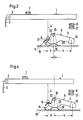
- FIGS. 3 and 4 differs from that of FIGS. 3 and 4 essentially only in that an eccentric 23 is provided instead of the movable bearing 22, by the rotation of the plunger 4 'laterally from the axis of rotation 10 of the Reaction lever 9 is pushed away by the amount f, so that here too the effective length d of the short lever arm 12 can be increased by the amount f to d '.
- the keyboard of Fig. 7 differs from that of FIGS. 5 and 6 only in that instead of the eccentric 23, a slide 24 is provided, which engages on a plunger 4 'connected angle piece 25 or directly on the plunger 4' and the plunger 4 'can bend away from the axis of rotation 10 by the horizontal displacement of the slide 24 by the amount f.
- the displaceable bearings 22 according to FIGS. 3 and 4, the eccentric 23 according to FIGS. 5 and 6 and the slide 24 according to FIG. 7 are infinitely adjustable and can be locked in the respectively set position.
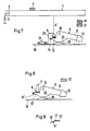
- the keyboard of Fig. 8 differs from the previous embodiments in that here the cam piece 14 'practically the entire length of the lever arm 12' of the reaction lever 9 supports and is only continuously bent over the entire length, without kinking. With such a shape, a particularly soft slip-through effect can be achieved, with an elastic section of the curve piece 14 'being unnecessary. With this keyboard, too, one of the mentioned setting options according to FIGS. 3 to 7 can be provided for the effective lever arm length d.
- Fig. 9 shows a modified curve piece 14 ⁇ , in which the end portions 15 'and 16' are slightly curved upwards and the bend 17 is also provided. If desired, this curve piece 14 ⁇ can be provided instead of the curve pieces 14 and 14 '.
- Another modification, not shown, of the keyboards shown can be that the short lever arm of the key 1, on which the return spring 3 engages, extends and both the plunger 4 or 4 'and the reaction lever 9 in kinematic reversal on the top of this extended lever arm be arranged, the short lever arm 12 or 12 'of the reaction lever 9 and the long lever arm 11 are on the same side of the axis of rotation of the reaction lever and should be directed towards the actuation end of the button 1.
Applications Claiming Priority (2)
| Application Number | Priority Date | Filing Date | Title |
|---|---|---|---|
| DE3905646 | 1989-02-24 | ||
| DE3905646A DE3905646C1 (fr) | 1989-02-24 | 1989-02-24 |
Publications (3)
| Publication Number | Publication Date |
|---|---|
| EP0384120A2 true EP0384120A2 (fr) | 1990-08-29 |
| EP0384120A3 EP0384120A3 (fr) | 1992-05-20 |
| EP0384120B1 EP0384120B1 (fr) | 1998-03-25 |
Family
ID=6374773
Family Applications (1)
| Application Number | Title | Priority Date | Filing Date |
|---|---|---|---|
| EP90100977A Expired - Lifetime EP0384120B1 (fr) | 1989-02-24 | 1990-01-18 | Clavier pour un orgue électronique ayant l'effet d'un piano |
Country Status (7)
| Country | Link |
|---|---|
| US (1) | US4993305A (fr) |
| EP (1) | EP0384120B1 (fr) |
| KR (1) | KR940003152B1 (fr) |
| AT (1) | ATE164467T1 (fr) |
| DE (2) | DE3905646C1 (fr) |
| DK (1) | DK0384120T3 (fr) |
| ES (1) | ES2116968T3 (fr) |
Cited By (3)
| Publication number | Priority date | Publication date | Assignee | Title |
|---|---|---|---|---|
| FR2731292A1 (fr) * | 1995-03-03 | 1996-09-06 | Perrin Claude | Capteur de deplacement dans un systeme d'analyse du mouvement des touches d'un piano |
| WO1996027868A1 (fr) * | 1995-03-03 | 1996-09-12 | Claude Perin | Capteur de deplacement dans un systeme d'analyse du mouvement des touches d'un piano |
| EP2169661A1 (fr) * | 2008-09-25 | 2010-03-31 | Yamaha Corporation | Instrument à clavier |
Families Citing this family (13)
| Publication number | Priority date | Publication date | Assignee | Title |
|---|---|---|---|---|
| US5243125A (en) * | 1991-03-22 | 1993-09-07 | Kabushiki Kaisha Kawai Gakki Seisakusho | Keyboard apparatus for electronic musical instrument having cooperating jacks and hammers |
| JP2528588Y2 (ja) * | 1991-04-24 | 1997-03-12 | 株式会社河合楽器製作所 | 電子楽器の鍵盤装置 |
| US5661082A (en) * | 1995-01-20 | 1997-08-26 | Motorola, Inc. | Process for forming a semiconductor device having a bond pad |
| US6060653A (en) * | 1999-05-28 | 2000-05-09 | Willis; Raymon A. | Method and apparatus for adjusting keys of a musical keyboard instrument from a weighted action to synthesizer feel |
| US6930234B2 (en) | 2002-06-19 | 2005-08-16 | Lanny Davis | Adjustable keyboard apparatus and method |
| JP5228742B2 (ja) * | 2008-09-25 | 2013-07-03 | ヤマハ株式会社 | 鍵盤装置 |
| JP5169680B2 (ja) * | 2008-09-25 | 2013-03-27 | ヤマハ株式会社 | 鍵盤装置 |
| JP5169681B2 (ja) * | 2008-09-25 | 2013-03-27 | ヤマハ株式会社 | 鍵盤装置 |
| JP5552260B2 (ja) * | 2009-05-07 | 2014-07-16 | 株式会社河合楽器製作所 | 電子鍵盤楽器の鍵盤装置 |
| JP5966685B2 (ja) * | 2012-07-02 | 2016-08-10 | ヤマハ株式会社 | 電子楽器の鍵盤装置 |
| JP6340184B2 (ja) * | 2013-10-31 | 2018-06-06 | 株式会社河合楽器製作所 | 鍵盤楽器のハンマー装置 |
| WO2017164296A1 (fr) * | 2016-03-25 | 2017-09-28 | ヤマハ株式会社 | Dispositif de clavier |
| JP6930258B2 (ja) * | 2017-07-12 | 2021-09-01 | カシオ計算機株式会社 | 鍵盤装置 |
Citations (5)
| Publication number | Priority date | Publication date | Assignee | Title |
|---|---|---|---|---|
| DE44061C (de) * | J. REISER in Berlin, Simeonstr. 24 | Mechanik für Flügel und tafelförmige Klaviere | ||
| DE51412C (de) * | G. LYON in Paris, Rue de Bondy 48 | Pianoforte-Mechanik mit Schnellauslösung | ||
| US4667563A (en) * | 1985-01-22 | 1987-05-26 | Kabushiki Kaisha Kawai Gakki Seisakusho | Key apparatus for electronic musical instrument |
| DE3601892A1 (de) * | 1986-01-23 | 1987-07-30 | Reinhard Franz | Tastatur fuer ein tasteninstrument mit klavieranschlag-dynamik |
| EP0270966A2 (fr) * | 1986-12-06 | 1988-06-15 | Reinhard Franz | Clavier pour un orgue électronique |
Family Cites Families (4)
| Publication number | Priority date | Publication date | Assignee | Title |
|---|---|---|---|---|
| DE252696C (fr) * | ||||
| US4217803A (en) * | 1979-01-02 | 1980-08-19 | Arp Instruments, Inc. | Piano-action keyboard |
| DD252696A1 (de) * | 1986-09-08 | 1987-12-23 | Ulrich Hermann | Einrichtung zur anschlagsabhaengigen ansteuerung elektronischer klangerzeuger |
| US4901614A (en) * | 1986-10-06 | 1990-02-20 | Yamaha Corporation | Keyboard apparatus of electronic musical instrument |
-
1989
- 1989-02-24 DE DE3905646A patent/DE3905646C1/de not_active Expired - Fee Related
-
1990
- 1990-01-18 EP EP90100977A patent/EP0384120B1/fr not_active Expired - Lifetime
- 1990-01-18 ES ES90100977T patent/ES2116968T3/es not_active Expired - Lifetime
- 1990-01-18 DK DK90100977T patent/DK0384120T3/da active
- 1990-01-18 AT AT90100977T patent/ATE164467T1/de not_active IP Right Cessation
- 1990-01-18 DE DE59010816T patent/DE59010816D1/de not_active Expired - Fee Related
- 1990-02-23 US US07/484,866 patent/US4993305A/en not_active Expired - Fee Related
- 1990-02-24 KR KR1019900002387A patent/KR940003152B1/ko not_active IP Right Cessation
Patent Citations (5)
| Publication number | Priority date | Publication date | Assignee | Title |
|---|---|---|---|---|
| DE44061C (de) * | J. REISER in Berlin, Simeonstr. 24 | Mechanik für Flügel und tafelförmige Klaviere | ||
| DE51412C (de) * | G. LYON in Paris, Rue de Bondy 48 | Pianoforte-Mechanik mit Schnellauslösung | ||
| US4667563A (en) * | 1985-01-22 | 1987-05-26 | Kabushiki Kaisha Kawai Gakki Seisakusho | Key apparatus for electronic musical instrument |
| DE3601892A1 (de) * | 1986-01-23 | 1987-07-30 | Reinhard Franz | Tastatur fuer ein tasteninstrument mit klavieranschlag-dynamik |
| EP0270966A2 (fr) * | 1986-12-06 | 1988-06-15 | Reinhard Franz | Clavier pour un orgue électronique |
Cited By (4)
| Publication number | Priority date | Publication date | Assignee | Title |
|---|---|---|---|---|
| FR2731292A1 (fr) * | 1995-03-03 | 1996-09-06 | Perrin Claude | Capteur de deplacement dans un systeme d'analyse du mouvement des touches d'un piano |
| WO1996027868A1 (fr) * | 1995-03-03 | 1996-09-12 | Claude Perin | Capteur de deplacement dans un systeme d'analyse du mouvement des touches d'un piano |
| EP2169661A1 (fr) * | 2008-09-25 | 2010-03-31 | Yamaha Corporation | Instrument à clavier |
| US8158876B2 (en) | 2008-09-25 | 2012-04-17 | Yamaha Corporation | Keyboard apparatus |
Also Published As
| Publication number | Publication date |
|---|---|
| ES2116968T3 (es) | 1998-08-01 |
| EP0384120A3 (fr) | 1992-05-20 |
| US4993305A (en) | 1991-02-19 |
| DK0384120T3 (da) | 1998-12-21 |
| DE3905646C1 (fr) | 1990-08-02 |
| EP0384120B1 (fr) | 1998-03-25 |
| DE59010816D1 (de) | 1998-04-30 |
| KR940003152B1 (ko) | 1994-04-15 |
| ATE164467T1 (de) | 1998-04-15 |
| KR900013450A (ko) | 1990-09-05 |
Similar Documents
| Publication | Publication Date | Title |
|---|---|---|
| EP0384120B1 (fr) | Clavier pour un orgue électronique ayant l'effet d'un piano | |
| EP0270966B1 (fr) | Clavier pour un orgue électronique | |
| DE3516585A1 (de) | Daempfungsmechanismus fuer ein klavier | |
| DE602006000246T2 (de) | Aktionsmechanismus für ein Klavier | |
| DE3833317C2 (de) | Anschlagvorrichtung für Konzertpiano | |
| DE10392654B4 (de) | Saitenschlagvorrichtung eines Klaviers | |
| DE19510150A1 (de) | Dämpfereinheit für einen Flügel | |
| DE3730100A1 (de) | Betaetigungsmechanismus fuer ein wandklavier | |
| DE4117453A1 (de) | Daempfungsvorrichtung fuer einen fluegel | |
| DE102004002713B4 (de) | Mechanik | |
| AT514688B1 (de) | Piano-Mechanik mit mehreren Tasten | |
| DE4422817A1 (de) | Klavier mit einem Mechanismus zur Regulierung der Saitenanschlagbewegung | |
| DE102004029267A1 (de) | Rückhemmung für ein Klavier | |
| DE112004001392T5 (de) | Saitenanschlagvorrichtung für ein Klavier | |
| DE19538267C2 (de) | Tastaturanordnung für Tastenmusikinstrumente | |
| DE4040729C2 (fr) | ||
| DE19703422A1 (de) | Repetitionseinrichtung für Klaviere | |
| DE10016122B4 (de) | Tastenmusikinstrument, das zwischen einer Akustikklangbetriebsart und einer stummen Betriebsart wechseln kann, sowie darin umfaßtes Stummschaltungssystem | |
| DE60103642T2 (de) | Dämpfereinstellvorrichtung | |
| DE2426016C2 (de) | Tastatur mit Trägheitseffekt für Musikinstrumente | |
| AT523227B1 (de) | Klavier | |
| DE19703450A1 (de) | Verbesserte Repetitionsschenkel für Flügel | |
| DE3730099A1 (de) | Anordnung des wipperendstueckes fuer ein wandklavier | |
| DE4213469A1 (de) | Tastatur für ein klavierartiges Musikinstrument | |
| DE3543064C2 (fr) |
Legal Events
| Date | Code | Title | Description |
|---|---|---|---|
| PUAI | Public reference made under article 153(3) epc to a published international application that has entered the european phase |
Free format text: ORIGINAL CODE: 0009012 |
|
| AK | Designated contracting states |
Kind code of ref document: A2 Designated state(s): AT BE CH DE DK ES FR GB GR IT LI LU NL SE |
|
| PUAL | Search report despatched |
Free format text: ORIGINAL CODE: 0009013 |
|
| AK | Designated contracting states |
Kind code of ref document: A3 Designated state(s): AT BE CH DE DK ES FR GB GR IT LI LU NL SE |
|
| 17P | Request for examination filed |
Effective date: 19920619 |
|
| 17Q | First examination report despatched |
Effective date: 19940721 |
|
| RAP1 | Party data changed (applicant data changed or rights of an application transferred) |
Owner name: FRANZ, REINHARD |
|
| 18R | Application refused |
Effective date: 19941202 |
|
| 18RA | Request filed for re-establishment of rights before grant |
Effective date: 19960319 |
|
| 18RR | Decision to grant the request for re-establishment of rights before grant |
Free format text: 960422 ANGENOMMEN |
|
| GRAH | Despatch of communication of intention to grant a patent |
Free format text: ORIGINAL CODE: EPIDOS IGRA |
|
| REG | Reference to a national code |
Ref country code: DE Ref legal event code: 8570 |
|
| GRAH | Despatch of communication of intention to grant a patent |
Free format text: ORIGINAL CODE: EPIDOS IGRA |
|
| RAP1 | Party data changed (applicant data changed or rights of an application transferred) |
Owner name: FATAR S.R.L. |
|
| GRAA | (expected) grant |
Free format text: ORIGINAL CODE: 0009210 |
|
| AK | Designated contracting states |
Kind code of ref document: B1 Designated state(s): AT BE CH DE DK ES FR GB GR IT LI LU NL SE |
|
| REF | Corresponds to: |
Ref document number: 164467 Country of ref document: AT Date of ref document: 19980415 Kind code of ref document: T |
|
| GBT | Gb: translation of ep patent filed (gb section 77(6)(a)/1977) |
Effective date: 19980326 |
|
| REF | Corresponds to: |
Ref document number: 59010816 Country of ref document: DE Date of ref document: 19980430 |
|
| ITF | It: translation for a ep patent filed |
Owner name: LENZI & C. |
|
| ET | Fr: translation filed | ||
| REG | Reference to a national code |
Ref country code: ES Ref legal event code: FG2A Ref document number: 2116968 Country of ref document: ES Kind code of ref document: T3 |
|
| REG | Reference to a national code |
Ref country code: DK Ref legal event code: T3 |
|
| PLBE | No opposition filed within time limit |
Free format text: ORIGINAL CODE: 0009261 |
|
| STAA | Information on the status of an ep patent application or granted ep patent |
Free format text: STATUS: NO OPPOSITION FILED WITHIN TIME LIMIT |
|
| 26N | No opposition filed | ||
| REG | Reference to a national code |
Ref country code: GB Ref legal event code: IF02 |
|
| REG | Reference to a national code |
Ref country code: CH Ref legal event code: AEN Free format text: BERICHTIGUNG. Ref country code: CH Ref legal event code: NV Representative=s name: HEPP, WENGER & RYFFEL AG Ref country code: CH Ref legal event code: PUE Owner name: REINHARD FRANZ Free format text: WERSI GMBH & CO.#AM EICHELGAERTCHEN#HALSENBACH (DE) -TRANSFER TO- REINHARD FRANZ#TULPENSTRASSE 15#EMMELSHAUSEN (DE) |
|
| PGFP | Annual fee paid to national office [announced via postgrant information from national office to epo] |
Ref country code: ES Payment date: 20080215 Year of fee payment: 19 Ref country code: DK Payment date: 20080122 Year of fee payment: 19 |
|
| PGFP | Annual fee paid to national office [announced via postgrant information from national office to epo] |
Ref country code: SE Payment date: 20080128 Year of fee payment: 19 Ref country code: NL Payment date: 20080130 Year of fee payment: 19 Ref country code: IT Payment date: 20080130 Year of fee payment: 19 Ref country code: GB Payment date: 20080116 Year of fee payment: 19 Ref country code: LU Payment date: 20080123 Year of fee payment: 19 |
|
| PGFP | Annual fee paid to national office [announced via postgrant information from national office to epo] |
Ref country code: AT Payment date: 20080122 Year of fee payment: 19 |
|
| PGFP | Annual fee paid to national office [announced via postgrant information from national office to epo] |
Ref country code: CH Payment date: 20080401 Year of fee payment: 19 Ref country code: FR Payment date: 20080129 Year of fee payment: 19 Ref country code: DE Payment date: 20080331 Year of fee payment: 19 |
|
| PGFP | Annual fee paid to national office [announced via postgrant information from national office to epo] |
Ref country code: BE Payment date: 20080131 Year of fee payment: 19 |
|
| PGFP | Annual fee paid to national office [announced via postgrant information from national office to epo] |
Ref country code: GR Payment date: 20080129 Year of fee payment: 19 |
|
| REG | Reference to a national code |
Ref country code: CH Ref legal event code: PL |
|
| EUG | Se: european patent has lapsed | ||
| GBPC | Gb: european patent ceased through non-payment of renewal fee |
Effective date: 20090118 |
|
| NLV4 | Nl: lapsed or anulled due to non-payment of the annual fee |
Effective date: 20090801 |
|
| REG | Reference to a national code |
Ref country code: DK Ref legal event code: EBP |
|
| PG25 | Lapsed in a contracting state [announced via postgrant information from national office to epo] |
Ref country code: AT Free format text: LAPSE BECAUSE OF NON-PAYMENT OF DUE FEES Effective date: 20090118 Ref country code: DE Free format text: LAPSE BECAUSE OF NON-PAYMENT OF DUE FEES Effective date: 20090801 Ref country code: CH Free format text: LAPSE BECAUSE OF NON-PAYMENT OF DUE FEES Effective date: 20090131 Ref country code: LI Free format text: LAPSE BECAUSE OF NON-PAYMENT OF DUE FEES Effective date: 20090131 |
|
| REG | Reference to a national code |
Ref country code: FR Ref legal event code: ST Effective date: 20091030 |
|
| PG25 | Lapsed in a contracting state [announced via postgrant information from national office to epo] |
Ref country code: GB Free format text: LAPSE BECAUSE OF NON-PAYMENT OF DUE FEES Effective date: 20090118 Ref country code: NL Free format text: LAPSE BECAUSE OF NON-PAYMENT OF DUE FEES Effective date: 20090801 |
|
| PG25 | Lapsed in a contracting state [announced via postgrant information from national office to epo] |
Ref country code: GR Free format text: LAPSE BECAUSE OF NON-PAYMENT OF DUE FEES Effective date: 20090804 Ref country code: BE Free format text: LAPSE BECAUSE OF NON-PAYMENT OF DUE FEES Effective date: 20090131 |
|
| REG | Reference to a national code |
Ref country code: ES Ref legal event code: FD2A Effective date: 20090119 |
|
| PG25 | Lapsed in a contracting state [announced via postgrant information from national office to epo] |
Ref country code: FR Free format text: LAPSE BECAUSE OF NON-PAYMENT OF DUE FEES Effective date: 20090202 Ref country code: ES Free format text: LAPSE BECAUSE OF NON-PAYMENT OF DUE FEES Effective date: 20090119 |
|
| PG25 | Lapsed in a contracting state [announced via postgrant information from national office to epo] |
Ref country code: DK Free format text: LAPSE BECAUSE OF NON-PAYMENT OF DUE FEES Effective date: 20090731 |
|
| PG25 | Lapsed in a contracting state [announced via postgrant information from national office to epo] |
Ref country code: IT Free format text: LAPSE BECAUSE OF NON-PAYMENT OF DUE FEES Effective date: 20090118 |
|
| PG25 | Lapsed in a contracting state [announced via postgrant information from national office to epo] |
Ref country code: LU Free format text: LAPSE BECAUSE OF NON-PAYMENT OF DUE FEES Effective date: 20090118 |
|
| PG25 | Lapsed in a contracting state [announced via postgrant information from national office to epo] |
Ref country code: SE Free format text: LAPSE BECAUSE OF NON-PAYMENT OF DUE FEES Effective date: 20090119 |