EP0384120A2 - Electronic organ keyboard with piano effect - Google Patents
Electronic organ keyboard with piano effect Download PDFInfo
- Publication number
- EP0384120A2 EP0384120A2 EP90100977A EP90100977A EP0384120A2 EP 0384120 A2 EP0384120 A2 EP 0384120A2 EP 90100977 A EP90100977 A EP 90100977A EP 90100977 A EP90100977 A EP 90100977A EP 0384120 A2 EP0384120 A2 EP 0384120A2
- Authority
- EP
- European Patent Office
- Prior art keywords
- plunger
- rotation
- axis
- curve piece
- reaction lever
- Prior art date
- Legal status (The legal status is an assumption and is not a legal conclusion. Google has not performed a legal analysis and makes no representation as to the accuracy of the status listed.)
- Granted
Links
Images


Classifications
-
- G—PHYSICS
- G10—MUSICAL INSTRUMENTS; ACOUSTICS
- G10H—ELECTROPHONIC MUSICAL INSTRUMENTS; INSTRUMENTS IN WHICH THE TONES ARE GENERATED BY ELECTROMECHANICAL MEANS OR ELECTRONIC GENERATORS, OR IN WHICH THE TONES ARE SYNTHESISED FROM A DATA STORE
- G10H1/00—Details of electrophonic musical instruments
- G10H1/32—Constructional details
- G10H1/34—Switch arrangements, e.g. keyboards or mechanical switches specially adapted for electrophonic musical instruments
- G10H1/344—Structural association with individual keys
- G10H1/346—Keys with an arrangement for simulating the feeling of a piano key, e.g. using counterweights, springs, cams
-
- G—PHYSICS
- G10—MUSICAL INSTRUMENTS; ACOUSTICS
- G10C—PIANOS, HARPSICHORDS, SPINETS OR SIMILAR STRINGED MUSICAL INSTRUMENTS WITH ONE OR MORE KEYBOARDS
- G10C3/00—Details or accessories
- G10C3/12—Keyboards; Keys
Definitions
- the invention relates to a keyboard for an electronic organ with piano effect, in which each key is pivotally mounted against spring force about a first horizontal axis of rotation and via a plunger attached to the key when the key is pressed against a curve piece on a second horizontal axis of rotation pivots the reaction lever and swivels it while moving the curve piece first against a large and then against a smaller reaction force from a first end position to a second end position, the large reaction force due to the acceleration of an additional mass attached to the reaction lever and the smaller reaction force due to an increase in the distance the contact point of the tappet on the curve piece is caused by the axis of rotation when the curve piece is moved away.
- the known key keyboard of the generic type (EP 270 966 A2) is used to actuate the key on the plunger when the key is pressed practiced transferring the stop force practically completely to an arm of the reaction lever, which has the curve piece and is provided with the additional mass at the end, as is the case with classic piano mechanics.
- the plunger can therefore be designed simply as a straight rod without an additional lever arm as in the conventional jack of classical piano mechanics and without its release man with which the lever arm of the jack comes into contact, since the second reaction lever arm takes over the release function.
- the reaction lever arm pivoting the plunger about a multi-part joint between the plunger and the reaction lever is provided with a cushion in order to avoid impact noises, in particular when the plunger is reset.
- such a cushion is not only complex, but also results from its flexibility also no precisely defined trigger point at which the plunger begins to slip on the curve section in order to simulate the sudden decrease in the reaction force.
- the cushion loses its flexibility after a long time, so that the damping of the impact noises is reduced.
- the invention has for its object to provide a keyboard of the generic type that causes less impact noise with less effort and maintains a defined trigger point.
- this object is achieved in that in the rest position of the unactuated key the distance of the contact point of the tappet on the curve piece from the button is greater than the distance of the button from the axis of rotation of the reaction lever and that the tappet only comes into contact with the curve piece and with the button is rigidly connected.
- the plunger only interacts with the cam piece to rotate the reaction lever against the weight and inertia of the additional mass, not only increasing the distance of the plunger from the axis of rotation of the reaction lever, but also the cam piece from the beginning with one (with the plunger initially in the vertical position) is constantly moved in the opposite direction to the horizontal movement component of the plunger, so that a deflection angle of the plunger corresponding solely to the pivoting angle of the key is sufficient for the curve piece to exceed the trigger point at which the slip occurs effect starts to leave.
- the plunger is therefore not carried by an arm of the reaction lever. Accordingly, there is no cushion on the lever arm of the reaction lever that interacts with the tappet, and the trigger point remains unaffected. Furthermore, there is no multi-part swivel joint between the plunger and the button.
- the cam piece in the rest position of the unactuated key is supported only by the plunger resting on the cam piece against the force caused by the weight of the additional mass and the plunger abuts the curve piece in every phase of its rotational movement.
- the surface of the curve piece to be moved away from the tappet has a kink parallel to the axis of rotation of the reaction lever, the sections of the surface adjoining the kink being flat or upward and forming an obtuse angle and one section closer than the other is at the axis of rotation of the reaction lever.
- the curve piece is continuously curved over its entire length. In this way it is possible, if desired, to have a particularly soft slipping effect, i.e. Achieve transition from a high to a low key resistance.
- the tappet In the inoperative position of the unactuated key, the tappet can rest with its free end surface only on the portion of the surface of the curve piece which is closest to the axis of rotation of the reaction lever. This prevents the slipping effect from being felt too early and too clearly if the contact point of the ram is initially too close to the transition point, such as the kink, e.g. if the initial key resistance is adjustable so that the distance of the longitudinal axis of the plunger from the axis of rotation of the reaction lever is adjustable.
- each plunger can be elastically flexible, in particular have spring steel sheet. It then bends slightly when the slip effect occurs and thus contributes to a rapid reduction in the key resistance during the slip.
- the distance of the longitudinal axis of the plunger from the axis of rotation of the reaction lever is adjustable by a laterally acting on the plunger and laterally bending away eccentric or slide, in order to set the initial key resistance when actuated in a simple manner.
- the setting of the key resistance can be achieved in that the bearings of the reaction lever axis of rotation can be moved transversely to the plane of the unactuated plunger.
- a further development may consist in that the curve piece is an elastically flexible strip, one end section of which is fastened to a support surface of the reaction lever and the other end section of which protrudes from the reaction lever in the plane of rotation, and the plunger in the rest position of the actuated key on the preceding one End section of the curve piece sits.
- the tappet reaches the unsupported end section of the elastic curve section, a sudden decrease in the key resistance is achieved due to the elastic yielding of the curve section in the region of the unsupported end section. If the curve piece also has a kink, the exceeding of the kink causes an additional, sudden decrease in the key resistance as a result of the elastic deflection of the slide piece.
- the tappet is also elastically flexible, its deflection overlaps the deflection of the curve section, with the result that the key resistance yields particularly strongly.
- the reaction lever with the additional mass moves to the upper end position and then falls back a little bit, in order to finally rest on the plunger with the elastic end section of the curve piece while the button is still depressed. In this simple manner, an unpleasant reaction of the reaction lever to the button is cushioned.
- the reaction lever is held in a position which enables rapid repetition, similar to a piano hammer in a position close to its associated string.
- the curve piece can be supported by the reaction lever essentially over its entire length.
- the reaction lever can interact with a vibration damper which dampens free vibrations of the reaction lever about its axis of rotation.
- a simple embodiment of the vibration damper can be that it is in frictional contact with the reaction lever. This results in friction damping.
- the vibration damper can be a leaf spring that bears against the reaction lever under pretension. This results in a particularly simple design of the vibration damper.
- One of the two abutting surfaces of the curve piece and tappet can be smooth and the other can be formed by a cushion, which preferably protrudes from a depression.
- the cushion contributes to noise reduction and can be moved with little friction on the smooth surface when the key is pressed, so that the key resistance is only marginally influenced by the friction.
- the low frictional resistance between the upholstery and the curve piece also contributes to increasing the service life of the upholstery.
- the upholstery of the upholstery ensures that the upholstery is held securely.
- each key 1 for actuating an electrical switching element is pivotally mounted about a horizontal axis of rotation 2 against the force of a return spring 3.
- a plunger 4 projects approximately vertically from the key 1 in the pivoting plane of the key 1.
- the plunger 4 is rigid and in one piece with the button 1, but can also be rigid, i.e. without swivel, to be attached to button 1.
- the plunger 4 is provided with an axial recess 5 (FIG. 1b), in which a cushion 6 made of felt is embedded and protrudes axially.
- a reaction lever 9 is mounted in the same plane as the key 1 so as to be pivotable about an axis of rotation 10 parallel to the axis of rotation 2 of the key 1.
- the reaction lever 9 has a longer lever arm 11 and a shorter lever arm 12, which are directed approximately in opposite directions and are arranged on both sides of the axis of rotation 10.
- the longer lever arm 11 is provided at its free end with an additional mass 13 (or a weight) made of a specifically much heavier material, preferably lead, than the material of the reaction lever 9, which is preferably made of plastic.
- a kinked curve piece 14 (see in particular Fig. 1a) in the form of a strip of spring steel sheet is attached with its one end section 15, so that the short lever arm 12 supports this end section 15, during which the free end of the lever arm 12 projecting free end portion 16 of the curve piece 14 is freely flexible.
- the tops of the two end sections 15 and 16, which lie on both sides of the bend 17 of the curve piece 14, form an obtuse angle and face the underside of the key 1.
- the top of the curve piece 14 is polished smooth and the position of the curve piece 14 is selected so that the plunger 4 in the rest position of the unactuated button 1 shown in FIG.
- a vibration damper 19 in the form of an upwardly arched leaf spring is attached at one end to a frame 18 of the keyboard.
- the leaf spring 19 is under prestress in frictional contact with a surface 20 of the reaction lever 9 which is concentric with the axis of rotation 10 of the reaction lever 9 in order to dampen vibrations of the reaction lever 9 primarily in the end position according to FIG. 1, but also in the end position according to FIG. 2.
- the distance of the contact point of the tappet 4 on the curve piece 14 from the button 1 is greater than the distance of the button 1 from the axis of rotation 10 already in the rest position of the unactuated button 1 according to FIG. 1 of the reaction lever 9.
- the tappet 4 only comes into contact with the cam piece 14 in each phase of its rotational movement. This has the consequence that the horizontal distance of the curve piece 14 from the axis of rotation 10 decreases relatively rapidly in the course of the rotary movement of the reaction lever 9 when the button 1 is depressed, the relative speeds of the cushion 6 and the curve piece 14 adding up, which also contributes to to make the transition from high to low key resistance in the manner of a slipping effect more noticeable for the player.
- the vibration damper 19 dampens any torsional vibrations of the reaction lever 9 about the axis of rotation 10 in the rest position of the key 1 according to FIG. 2 if it is still held down, or also in the rest position according to FIG. 1 after the key 1 in this Rest position has returned.
- the transmission ratio of the reaction lever 9 and thus the key resistance can also be set to the desired value when playing (while the keyboard is being operated).
- FIGS. 3 and 4 differs from that of FIGS. 3 and 4 essentially only in that an eccentric 23 is provided instead of the movable bearing 22, by the rotation of the plunger 4 'laterally from the axis of rotation 10 of the Reaction lever 9 is pushed away by the amount f, so that here too the effective length d of the short lever arm 12 can be increased by the amount f to d '.
- the keyboard of Fig. 7 differs from that of FIGS. 5 and 6 only in that instead of the eccentric 23, a slide 24 is provided, which engages on a plunger 4 'connected angle piece 25 or directly on the plunger 4' and the plunger 4 'can bend away from the axis of rotation 10 by the horizontal displacement of the slide 24 by the amount f.
- the displaceable bearings 22 according to FIGS. 3 and 4, the eccentric 23 according to FIGS. 5 and 6 and the slide 24 according to FIG. 7 are infinitely adjustable and can be locked in the respectively set position.
- the keyboard of Fig. 8 differs from the previous embodiments in that here the cam piece 14 'practically the entire length of the lever arm 12' of the reaction lever 9 supports and is only continuously bent over the entire length, without kinking. With such a shape, a particularly soft slip-through effect can be achieved, with an elastic section of the curve piece 14 'being unnecessary. With this keyboard, too, one of the mentioned setting options according to FIGS. 3 to 7 can be provided for the effective lever arm length d.
- Fig. 9 shows a modified curve piece 14 ⁇ , in which the end portions 15 'and 16' are slightly curved upwards and the bend 17 is also provided. If desired, this curve piece 14 ⁇ can be provided instead of the curve pieces 14 and 14 '.
- Another modification, not shown, of the keyboards shown can be that the short lever arm of the key 1, on which the return spring 3 engages, extends and both the plunger 4 or 4 'and the reaction lever 9 in kinematic reversal on the top of this extended lever arm be arranged, the short lever arm 12 or 12 'of the reaction lever 9 and the long lever arm 11 are on the same side of the axis of rotation of the reaction lever and should be directed towards the actuation end of the button 1.
Abstract
Description
Die Erfindung bezieht sich auf eine Tastatur für eine elektronische Orgel mit Klaviereffekt, bei der jede Taste gegen Federkraft um eine erste horizontale Drehachse schwenkbar gelagert ist und über einen an der Taste angebrachten Stößel bei Betätigung der Taste gegen ein Kurvenstück an einem um eine zweite horizontale Drehachse schwenkbaren Reaktionshebel drückt und diesen unter Abfahren des Kurvenstücks zunächst gegen eine große und dann gegen eine kleinere Reaktionskraft aus einer ersten Endlage in eine zweite Endlage schwenkt, wobei die große Reaktionskraft durch die Beschleunigung einer am Reaktionshebel angebrachten Zusatzmasse und die kleinere Reaktionskraft durch eine Zunahme des Abstands der Anlagestelle des Stößels an dem Kurvenstück von der Drehachse beim Abfahren des Kurvenstücks bewirkt wird.The invention relates to a keyboard for an electronic organ with piano effect, in which each key is pivotally mounted against spring force about a first horizontal axis of rotation and via a plunger attached to the key when the key is pressed against a curve piece on a second horizontal axis of rotation pivots the reaction lever and swivels it while moving the curve piece first against a large and then against a smaller reaction force from a first end position to a second end position, the large reaction force due to the acceleration of an additional mass attached to the reaction lever and the smaller reaction force due to an increase in the distance the contact point of the tappet on the curve piece is caused by the axis of rotation when the curve piece is moved away.
Unter "elektronische Orgel" sollen hier auch elektronische Klaviere oder sogenannte "Keybords" fallen.Electronic pianos or so-called "keyboards" should also be included here under "electronic organ".
Um für den Spieler einer elektronischen Orgel bei Wahl des Klaviereffekts das Anschlagverhalten einer Klaviertastatur zu simulieren, wird bei einer bekannten Tastatur der gattungsgemäßen Art (EP 270 966 A2) die bei der Betätigung der Taste über diese auf den Stößel ausge übte Anschlagskraft zunächst praktisch vollständig auf einen das Kurvenstück aufweisenden, mit der Zusatzmasse am Ende versehenen Arm des Reaktionshebels übertragen, wie dies bei einer klassischen Klaviermechanik der Fall ist. Aufgrund eines sehr gering gewählten Verhältnisses der Abstände von Stößel-Anlagestelle und Zusatzmassenschwerpunkt von der Drehachse des Reaktionshebels und vollständiger Übertragung der Stößelkraft auf den die Zusatzmasse tragenden Reaktionshebelarm ergibt sich von Anfang an eine verhältnismäßig hohe Beschleunigung der Zusatzmasse und damit eine entsprechend hohe Reaktionskraft (entsprechend dem Produkt aus Masse und Beschleunigung), wie bei einem klassischen Klavier. Kurz nach der Betätigung der Taste bewirkt ein zweiter Reaktionshebelarm eine Verschwenkung des Stößels, so daß dessen Kraft nicht mehr senkrecht auf das Kurvenstück (d.h. auf eine Tangente in der Stößel-Anlagestelle des Kurvenstücks) gerichtet ist, sondern der Stößel das Kurvenstück abzufahren beginnt, mit der Folge, daß nur noch eine Komponente der Stößelkraft auf das Kurvenstück bzw. den dieses tragenden Reaktionshebelarm wirksam ist. Dabei vergrößert sich gleichzeitig der Abstand des Stößels von der Drehachse des Reaktionshebels, und die Reaktionskraft des Reaktionshebels nimmt plötzlich entsprechend ab. Anschließend ist die Taste - entsprechend der klassischen Klaviermechanik - sehr leicht zu betätigen. Der Stößel kann daher einfach als geradlinige Stange ohne zusätzlichen Hebelarm wie bei der herkömmlichen Stoßzunge der klassischen Klaviermechanik und ohne deren Auslösepuppe, mit der der Hebelarm der Stoßzunge in Berührung kommt, ausgebildet sein, da der zweite Reaktionshebelarm die Auslösefunktion übernimmt. Der hierbei den Stößel um ein mehrteiliges Gelenk zwischen Stößel und Reaktionshebel verschwenkende Reaktionshebelarm ist mit einem Polster versehen, um Anschlaggeräusche, insbesondere bei der Rückstellung des Stößels, zu vermeiden. Ein solches Polster ist jedoch nicht nur aufwendig, sondern ergibt aufgrund seiner Nachgiebigkeit auch keinen genau definierten Auslösepunkt, bei dem der Stößel auf dem Kurvenstück durchzurutschen beginnt, um das plötzliche Nachlassen der Reaktionskraft zu simulieren. Darüber hinaus verliert das Polster nach längerer Zeit seine Nachgiebigkeit, so daß die Dämpfung der Anschlaggeräusche vermindert wird.In order to simulate the touch behavior of a piano keyboard for the player of an electronic organ when selecting the piano effect, the known key keyboard of the generic type (EP 270 966 A2) is used to actuate the key on the plunger when the key is pressed practiced transferring the stop force practically completely to an arm of the reaction lever, which has the curve piece and is provided with the additional mass at the end, as is the case with classic piano mechanics. Due to a very small ratio of the distances between the tappet contact point and the additional center of gravity from the axis of rotation of the reaction lever and the complete transfer of the tappet force to the reaction lever arm carrying the additional mass, there is a relatively high acceleration of the additional mass from the beginning and thus a correspondingly high reaction force (corresponding to the Product of mass and acceleration), like a classic piano. Shortly after pressing the button, a second reaction lever arm causes the plunger to pivot, so that its force is no longer directed perpendicularly to the curve piece (ie to a tangent in the plunger contact point of the curve piece), but rather the plunger begins to move along the curve piece with the consequence that only one component of the tappet force on the cam piece or the reaction lever arm carrying this is effective. At the same time, the distance of the plunger from the axis of rotation of the reaction lever increases, and the reaction force of the reaction lever suddenly decreases accordingly. Then the key is very easy to press - in accordance with classical piano mechanics. The plunger can therefore be designed simply as a straight rod without an additional lever arm as in the conventional jack of classical piano mechanics and without its release man with which the lever arm of the jack comes into contact, since the second reaction lever arm takes over the release function. The reaction lever arm pivoting the plunger about a multi-part joint between the plunger and the reaction lever is provided with a cushion in order to avoid impact noises, in particular when the plunger is reset. However, such a cushion is not only complex, but also results from its flexibility also no precisely defined trigger point at which the plunger begins to slip on the curve section in order to simulate the sudden decrease in the reaction force. In addition, the cushion loses its flexibility after a long time, so that the damping of the impact noises is reduced.
Es ist auch bekannt, z.B. aus der US-A-42 17 803, DE-B1-24 26 016 oder der DE-C2-36 01 892, den Stößel starr mit der Taste zu verbinden und ihn entweder insgesamt starr oder elastisch auszubilden.It is also known, e.g. from US-A-42 17 803, DE-B1-24 26 016 or DE-C2-36 01 892 to connect the plunger rigidly with the button and to design it either as a whole rigid or elastic.
Der Erfindung liegt die Aufgabe zugrunde, eine Tastatur der gattungsgemäßen Art anzugeben, die bei geringerem Aufwand geringere Anschlaggeräusche bewirkt und einen definierten Auslösepunkt beibehält.The invention has for its object to provide a keyboard of the generic type that causes less impact noise with less effort and maintains a defined trigger point.
Erfindungsgemäß ist diese Aufgabe dadurch gelöst, daß in der Ruhelage der unbetätigten Taste der Abstand der Anlagestelle des Stößels am Kurvenstück von der Taste größer als der Abstand der Taste von der Drehachse des Reaktionshebels ist und daß der Stößel nur mit dem Kurvenstück zur Anlage kommt und mit der Taste starr verbunden ist.According to the invention this object is achieved in that in the rest position of the unactuated key the distance of the contact point of the tappet on the curve piece from the button is greater than the distance of the button from the axis of rotation of the reaction lever and that the tappet only comes into contact with the curve piece and with the button is rigidly connected.
Bei dieser Ausbildung wirkt der Stößel nur mit dem Kurvenstück zusammen, um den Reaktionshebel gegen das Gewicht und die Trägheitskraft der Zusatzmasse zu drehen, wobei sich nicht nur der Abstand des Stößels von der Drehachse des Reaktionshebels vergrößert, sondern auch das Kurvenstück von Anfang an mit einer (bei anfänglich vertikaler Lage des Stößels) ständig zur Horizontalbewegungskomponente des Stößels entgegengesetzt gerichteten Bewegungskomponente bewegt wird, so daß ein allein dem Schwenkwinkel der Taste entsprechender Auslenkwinkel des Stößels ausreicht, um das Kurvenstück unter Überschreitung des Auslösepunktes, bei dem der Durchrutsch effekt beginnt, abzufahren. Der Stößel wird daher nicht durch einen Arm des Reaktionshebels mitgenommen. Entsprechend entfällt ein mit dem Stößel zusammenwirkendes Polster an einem Hebelarm des Reaktionshebels, und der Auslösepunkt bleibt unbeeinflußt. Ferner entfällt ein mehrteiliges Drehgelenk zwischen Stößel und Taste.In this embodiment, the plunger only interacts with the cam piece to rotate the reaction lever against the weight and inertia of the additional mass, not only increasing the distance of the plunger from the axis of rotation of the reaction lever, but also the cam piece from the beginning with one (with the plunger initially in the vertical position) is constantly moved in the opposite direction to the horizontal movement component of the plunger, so that a deflection angle of the plunger corresponding solely to the pivoting angle of the key is sufficient for the curve piece to exceed the trigger point at which the slip occurs effect starts to leave. The plunger is therefore not carried by an arm of the reaction lever. Accordingly, there is no cushion on the lever arm of the reaction lever that interacts with the tappet, and the trigger point remains unaffected. Furthermore, there is no multi-part swivel joint between the plunger and the button.
Vorzugsweise ist dafür gesorgt, daß das Kurvenstück in der Ruhelage der unbetätigten Taste nur durch den am Kurvenstück anliegenden Stößel gegen die durch das Gewicht der Zusatzmasse bewirkte Kraft abgestützt ist und der Stößel in jeder Phase seiner Drehbewegung am Kurvenstück anliegt. Hierbei entfällt auch ein gepolsterter Anschlag für den Reaktionshebel in seiner ersten Endlage. Die durch den Wegfall des Anschlags für den Reaktionshebel in seiner ersten Ruhelage bestehende Gefahr, daß der Stößel von dem Gleitstück abrutscht und sich der Reaktionshebel unter dem Gewicht der Zusatzmasse zurückdreht, so daß sich bei der Rückbewegung der Taste Stößel und Reaktionshebel blockieren, wird durch die ständige Anlage des Stößels am Kurvenstück in jeder Phase seiner Drehbewegung vermieden. Sodann kommt man ohne Einstelleinreichtung für den Ausgleich eines Spiels zwischen den beiden Berührungsflächen von Stößel und Kurvenstück in der ersten Endlage des Reaktionshebels aus, weil ein solches Spiel wegen des für diese Endlage fehlenden Anschlags durch das Gewicht der Zusatzmasse selbsttätig ausgeglichen wird.Preferably, it is ensured that the cam piece in the rest position of the unactuated key is supported only by the plunger resting on the cam piece against the force caused by the weight of the additional mass and the plunger abuts the curve piece in every phase of its rotational movement. There is also no padded stop for the reaction lever in its first end position. The danger of the plunger slipping off the slide and the reaction lever rotating under the weight of the additional mass, so that the plunger and reaction lever block when the key moves back, is eliminated by the removal of the stop for the reaction lever in its first rest position Constant contact of the tappet on the curve piece avoided in every phase of its rotary movement. Then there is no adjustment for the compensation of a game between the two contact surfaces of the plunger and curve piece in the first end position of the reaction lever, because such a game is automatically compensated for by the weight of the additional mass because of the lack of a stop for this end position.
Sodann ist es günstig, wenn die vom Stößel abzufahrende Oberfläche des Kurvenstücks einen zur Drehachse des Reaktionshebels parallelen Knick aufweist, wobei die an den Knick angrenzenden Abschnitte der Oberfläche eben oder nach oben gewölbt sind und einen überstumpfen Winkel bilden und der eine Abschnitt näher als der andere bei der Drehachse des Reaktionshebels liegt. Durch diesen Knick spürt der Spieler deutlich den Übergang bzw. Auslösepunkt von einem hohen zu einem niedrigen Tastenwiderstand.It is then expedient if the surface of the curve piece to be moved away from the tappet has a kink parallel to the axis of rotation of the reaction lever, the sections of the surface adjoining the kink being flat or upward and forming an obtuse angle and one section closer than the other is at the axis of rotation of the reaction lever. Through this kink, the player clearly feels the transition or trigger point from a high to a low key resistance.
Stattdessen ist es auch möglich, daß das Kurvenstück in seiner ganzen Länge stetig gebogen ist. Auf diese Weise ist es gewünschtenfalls möglich, einen besonders weichen Durchrutscheffekt, d.h. Übergang von einem hohen zu einem niedrigen Tastenwiderstand zu erzielen.Instead, it is also possible that the curve piece is continuously curved over its entire length. In this way it is possible, if desired, to have a particularly soft slipping effect, i.e. Achieve transition from a high to a low key resistance.
Der Stößel kann in der Ruhelage der unbetätigten Taste mit seiner freien Endfläche nur an dem der Drehachse des Reaktionshebels zunächstliegenden Abschnitt der Oberfläche des Kurvenstücks anliegt. Dadurch wird vermieden, daß der Durchrutscheffekt zu früh und zu deutlich spürbar wird, wenn die Anlagestelle des Stößels anfänglich zu dicht bei der Übergangsstelle, wie dem Knick, liegt, z.B. wenn der anfängliche Tastenwiderstand dadurch einstellbar ausgebildet ist, daß der Abstand der Längsachse des Stößels von der Drehachse des Reaktionshebels einstellbar ist.In the inoperative position of the unactuated key, the tappet can rest with its free end surface only on the portion of the surface of the curve piece which is closest to the axis of rotation of the reaction lever. This prevents the slipping effect from being felt too early and too clearly if the contact point of the ram is initially too close to the transition point, such as the kink, e.g. if the initial key resistance is adjustable so that the distance of the longitudinal axis of the plunger from the axis of rotation of the reaction lever is adjustable.
Wenn hierbei die Abstände der Längsachsen aller Stößel von einer gemeinsamen Drehachse aller Reaktionshebel gemeinsam verstellbar sind, ermöglicht dies eine besonders einfache gemeinsame und gleiche Einstellung des anfänglich bei der Tastenbetätigung auftretenden Tastenwiderstands.If the distances of the longitudinal axes of all plungers from a common axis of rotation of all reaction levers can be adjusted jointly, this enables a particularly simple, common and identical setting of the key resistance initially occurring when the key is pressed.
Ferner kann jeder Stößel elastisch biegsam sein, insbesondere Federstahlblech aufweisen. Er biegt sich dann beim Einsetzen des Durchrutscheffekts geringfügung durch und trägt damit zu einer raschen Verminderung des Tastenwiderstands während des Durchrutschens bei.Furthermore, each plunger can be elastically flexible, in particular have spring steel sheet. It then bends slightly when the slip effect occurs and thus contributes to a rapid reduction in the key resistance during the slip.
Sodann kann dafür gesorgt sein, daß der Abstand der Längsachse des Stößels von der Drehachse des Reaktionshebels durch einen seitlich auf den Stößel einwirkenden und diesen seitlich wegbiegenden Exzenter oder Schieber einstellbar ist, um den bei der Betätigung anfänglichen Tastenwiderstand auf einfache Weise einzustellen.Then it can be ensured that the distance of the longitudinal axis of the plunger from the axis of rotation of the reaction lever is adjustable by a laterally acting on the plunger and laterally bending away eccentric or slide, in order to set the initial key resistance when actuated in a simple manner.
Alternativ kann die Einstellung des Tastenwiderstands dadurch erreicht werden, daß die Lager der Reaktionshebel-Drehachse quer zur Ebene der unbetätigten Stößel verschiebbar sind.Alternatively, the setting of the key resistance can be achieved in that the bearings of the reaction lever axis of rotation can be moved transversely to the plane of the unactuated plunger.
Eine Weiterbildung kann darin bestehen, daß das Kurvenstück ein elastisch biegsamer Streifen ist, dessen einer Endabschnitt auf einer Stützfläche des Reaktionshebels befestigt ist und dessen anderer Endabschnitt in der Drehebene des Reaktionshebels von diesem absteht, und der Stößel in der Ruhelage der betätigten Taste auf dem vorstehenden Endabschnitt des Kurvenstücks aufsitzt. Wenn der Stößel bei dieser Ausbildung den nicht abgestützten Endabschnitt des elastischen Kurvenstücks erreicht, wird auf diese Weise ein plötzliches Nachlassen des Tastenwiderstandes infolge des elastischen Nachgebens des Kurvenstücks im Bereich des nicht abgestützten Endabschnitts erreicht. Wenn das Kurvenstück außerdem einen Knick aufweist, bewirkt das Überschreiten des Knicks ein zusätzliches, plötzliches Nachlassen des Tastenwiderstandes infolge der elastischen Durchbiegung des Gleitstücks. Wenn auch der Stößel elastisch biegsam ist, überlagert sich dessen Durchbiegung der Durchbiegung des Kurvenstücks mit der Folge, daß der Tastenwiderstand besonders stark nachgibt. Wenn die Taste bis zu einem unteren Anschlag niedergedrückt wird, bewegt sich der Reaktionshebel mit der Zusatzmasse bis zur oberen Endlage und fällt anschließend wieder etwas zurück, um sich schließlich mit dem elastischen Endabschnitt des Kurvenstücks bei immer noch niedergedrückter Taste am Stößel anzulegen. Auf diese einfache Weise wird ein unangenehmer Rückschlag des Reaktionshebels auf die Taste abgefedert. Außerdem wird dadurch der Reaktionshebel in einer Lage gehalten, die ein rasches Repetieren ermöglicht, ähnlich wie ein Hammer eines Klaviers in einer seiner ihm zugeordneten Saite nahen Stellung.A further development may consist in that the curve piece is an elastically flexible strip, one end section of which is fastened to a support surface of the reaction lever and the other end section of which protrudes from the reaction lever in the plane of rotation, and the plunger in the rest position of the actuated key on the preceding one End section of the curve piece sits. In this embodiment, when the tappet reaches the unsupported end section of the elastic curve section, a sudden decrease in the key resistance is achieved due to the elastic yielding of the curve section in the region of the unsupported end section. If the curve piece also has a kink, the exceeding of the kink causes an additional, sudden decrease in the key resistance as a result of the elastic deflection of the slide piece. If the tappet is also elastically flexible, its deflection overlaps the deflection of the curve section, with the result that the key resistance yields particularly strongly. When the button is pressed down to a lower stop, the reaction lever with the additional mass moves to the upper end position and then falls back a little bit, in order to finally rest on the plunger with the elastic end section of the curve piece while the button is still depressed. In this simple manner, an unpleasant reaction of the reaction lever to the button is cushioned. In addition, the reaction lever is held in a position which enables rapid repetition, similar to a piano hammer in a position close to its associated string.
Alternativ kann das Kurvenstück im wesentlichen über seine ganze Länge durch den Reaktionshebel unterstützt sein.Alternatively, the curve piece can be supported by the reaction lever essentially over its entire length.
Um ein gegebenenfalls störendes Nachschwingen des Reaktionshebels beim Erreichen seiner Endlage nach der Freigabe der Taste zu vermeiden, kann der Reaktionshebel mit einem Schwingungsdämpfer zusammenwirken, der freie Schwingungen des Reaktionshebels um seine Drehachse dämpft.In order to avoid any annoying reverberation of the reaction lever when it reaches its end position after the button is released, the reaction lever can interact with a vibration damper which dampens free vibrations of the reaction lever about its axis of rotation.
Eine einfache Ausgestaltung des Schwingungsdämpfers kann darin bestehen, daß er mit dem Reaktionshebel in reibender Berührung steht. Dies ergibt eine Dämpfung durch Reibung.A simple embodiment of the vibration damper can be that it is in frictional contact with the reaction lever. This results in friction damping.
Hierbei kann der Schwingungsdämpfer eine am Reaktionshebel unter Vorspannung anliegende Blattfeder sein. Dies ergibt eine besonders einfache Ausbildung des Schwingungsdämpfers.In this case, the vibration damper can be a leaf spring that bears against the reaction lever under pretension. This results in a particularly simple design of the vibration damper.
Wenn der Schwingungsdämpfer an einer zur Drehachse des Reaktionshebels konzentrischen Oberfläche des Reaktionshebels anliegt, ist der Reibungswiderstand und damit die Dämpfung in jeder Drehwinkellage des Reaktionshebels gleich.If the vibration damper rests on a surface of the reaction lever which is concentric with the axis of rotation of the reaction lever, the frictional resistance and thus the damping is the same in every rotational angle position of the reaction lever.
Die eine der beiden aneinander anliegenden Oberflächen von Kurvenstück und Stößel kann glatt und die andere durch ein Polster gebildet sein, das vorzugsweise aus einer Vertiefung vorsteht. Das Polster trägt zur Geräuschdämpfung bei und läßt sich bei der Tastenbetätigung mit geringer Reibung auf der glatten Oberfläche verschieben, so daß der Tastenwiderstand nur unmaßgeblich durch die Reibung beeinflußt wird. Der geringe Reibungswiderstand zwischen Polster und Kurvenstück trägt ferner zur Erhöhung der Lebensdauer des Polsters bei. Die Aufnahme des Polsters in eine Vertiefung sorgt für einen sicheren Halt des Polsters.One of the two abutting surfaces of the curve piece and tappet can be smooth and the other can be formed by a cushion, which preferably protrudes from a depression. The cushion contributes to noise reduction and can be moved with little friction on the smooth surface when the key is pressed, so that the key resistance is only marginally influenced by the friction. The low frictional resistance between the upholstery and the curve piece also contributes to increasing the service life of the upholstery. The upholstery of the upholstery ensures that the upholstery is held securely.
Die Erfindung und ihre Weiterbildungen werden nachstehend anhand schematischer Zeichnungen bevorzugter Ausführungsbeispiele näher beschrieben. Es zeigen:
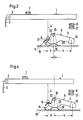
- Fig. 1 und 2 eine Seitenansicht eines Teils eines ersten Ausführungsbeispiels einer erfindungsgemäßen Tastatur in verschiedenen Betriebsstellungen, teilweise im Schnitt,
- Fig. 1a ein Kurvenstück eines Reaktionshebels der Tastatur nach den Fig. 1 und 2 in etwas größerem Maßstab,
- Fig. 1b einen Teil eines Stößels der Tastatur nach den Fig. 1 und 2 in etwas größerem Maßstab,
- Fig. 3 und 4 eine Seitenansicht eines Teils eines zweiten Ausführungsbeispiels einer erfindungsgemäßen Tastatur bei verschiedenen Lageeinstellungen des Reaktionshebels, teilweise im Schnitt,
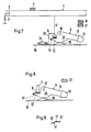
- Fig. 5 und 6 eine Seitenansicht eines Teils eines dritten Ausführungsbeispiels einer erfindungsgemäßen Tastatur bei verschiedenen Lageeinestellungen des Stößels, teilweise im Schnitt,
- Fig. 7 eine Seitenansicht eines Teils eines vierten Ausführungsbeispiels einer erfindungsgemäßen Tastatur, teilweise im Schnitt,
- Fig. 8 eine Seitenansicht eines Teils eines fünften Ausführungsbeispiels einer erfindungsgemäßen Tastatur, teilweise im Schnitt, und
- Fig. 9 ein weiteres abgewandeltes Kurvenstück des Reaktionshebels.
- 1 and 2 is a side view of part of a first embodiment of a keyboard according to the invention in different operating positions, partly in section,
- 1a shows a curve piece of a reaction lever of the keyboard according to FIGS. 1 and 2 on a somewhat larger scale,
- 1b shows a part of a plunger of the keyboard according to FIGS. 1 and 2 on a somewhat larger scale,
- 3 and 4 is a side view of part of a second embodiment of a keyboard according to the invention with different position settings of the reaction lever, partly in section,
- 5 and 6 is a side view of part of a third embodiment of a keyboard according to the invention with different positions of the plunger, partly in section,
- 7 is a side view of part of a fourth embodiment of a keyboard according to the invention, partly in section,
- Fig. 8 is a side view of part of a fifth embodiment of a keyboard according to the invention, partly in section, and
- Fig. 9 shows another modified curve piece of the reaction lever.
Bei der Tastatur nach den Fig. 1 und 2 ist jede Taste 1 zur Betätigung eines nicht dargestellten elektrischen Schaltelements um eine horizontale Drehachse 2 gegen die Kraft einer Rückholfeder 3 schwenkbar gelagert.1 and 2, each key 1 for actuating an electrical switching element, not shown, is pivotally mounted about a horizontal axis of
An der Unterseite des Betätigungshebelarms der Taste 1 steht ein Stößel 4 in der Schwenkebene der Taste 1 etwa senkrecht von der Taste 1 ab. Der Stößel 4 ist starr und einteilig mit der Taste 1 ausgebildet, kann jedoch auch starr, d.h. ohne Drehgelenk, an der Taste 1 befestigt sein. An seinem freien Ende ist der Stößel 4 mit einer axialen Vertiefung 5 (Fig. 1b) versehen, in der ein aus Filz bestehendes Polster 6 eingebettet ist und axial vorsteht.On the underside of the actuating lever arm of the key 1, a
In der in Fig. 1 dargestellten Ruhelage der unbetätigten Taste 1 wird die Taste 1 durch die Kraft der Rückholfeder 3 gegen einen gepolsterten Anschlag 7 und in der in Fig. 2 dargestellten Ruhelage bei betätigter Taste durch die Betätigungskraft gegen einen gepolsterten Anschlag 8 gedrückt.In the rest position of the unactuated key 1 shown in FIG. 1, the key 1 is pressed by the force of the return spring 3 against a
Unterhalb der Taste 1 ist ein Reaktionshebel 9 in der gleichen Ebene wie die Taste 1 um eine zur Drehachse 2 der Taste 1 parallele Drehachse 10 schwenkbar gelagert. Der Reaktionshebel 9 hat einen längeren Hebelarm 11 und einen kürzeren Hebelarm 12, die etwa entgegengesetzt gerichtet und beiderseits der Drehachse 10 angeordnet sind. Der längere Hebelarm 11 ist an seinem freien Ende mit einer Zusatzmasse 13 (bzw. einem Gewichtsstück) aus einem spezifisch sehr viel schwereren Material, vorzugsweise Blei, als das Material des Reaktionshebels 9, das vorzugsweise aus Kunststoff besteht, versehen. Während die Drehachse 10 des Reaktionshebels 9 auf der der Drehachse 2 der Taste 1 abgewandten Seite des Stößels 4 liegt, ragt der längere Hebelarm 11 des Reaktionshebels 9 von der dem Stößel 4 abgekehrten Seite der Drehachse 10 weg.Below the key 1, a
Auf der Oberseite des kurzen Hebelarms 12 des Reaktionshebels 9 ist ein abgeknicktes Kurvenstück 14 (siehe insbesondere Fig. 1a) in Form eines Streifens aus Federstahlblech mit seinem einen Endabschnitt 15 befestigt, so daß der kurze Hebelarm 12 diesen Endabschnitt 15 abstützt, während der über das freie Ende des Hebelarms 12 hinausragende freie Endabschnitt 16 des Kurvenstücks 14 frei biegsam ist. Die Oberseiten der beiden Endabschnitte 15 und 16, die beiderseits des Knicks 17 des Kurvenstücks 14 liegen, bilden einen überstumpfen Winkel und sind der Unterseite der Taste 1 zugekehrt. Die Oberseite des Kurvenstücks 14 ist glatt poliert und die Lage des Kurvenstücks 14 so gewählt, daß der Stößel 4 in der in Fig. 1 dargestellten Ruhelage der unbetätigten Taste 1 mit seiner freien, durch das Polster 6 gebildeten Endfläche nur an dem Endabschnitt 15 anliegt und der Abstand der Anlagestelle des Stößels 4 am Kurvenstück 14 von der (Unterseite der) Taste 1 größer als der Abstand der Drehachse 10 von der Taste 1 ist. Der auf dem kurzen Hebelarm 12 des Reaktionshebels 9 befestigte Endabschnitt 15 des Kurvenstücks 14 verläuft in der Ruhelage der unbetätigten Taste 1 nach Fig. 1 etwa horizontal.On the top of the
An einem Gestell 18 der Tastatur ist ein Schwingungsdämpfer 19 in Form einer nach oben gewölbten Blattfeder mit ihrem einen Ende befestigt. Die Blattfeder 19 steht unter Vorspannung in reibender Berührung mit einer zur Drehachse 10 des Reaktionshebels 9 konzentrischen Oberfläche 20 des Reaktionshebels 9, um Schwingungen des Reaktionshebels 9 vornehmlich in der Endlage nach Fig. 1, aber auch in der Endlage nach Fig. 2 zu dämpfen.A
Wenn die Taste 1 betätigt, d.h. niedergedrückt wird, so daß sie sich im Uhrzeigersinn um die Drehachse 2 dreht, drückt die untere Endfläche des Stößels 4 bzw. des Polsters 6 gegen den Endabschnitt 15 des Kurvenstücks 14. Dadurch wird der Reaktionshebel 9 entgegen dem Uhrzeigersinn um seine Drehachse 10 im wesentlichen gegen das Gewicht und die Massenträgheit der Zusatzmasse 13, übersetzt im Verhältnis der effektiven Hebelarmlängen, d.h. der horizontalen Abstände der Anlagestelle des Stößels 4 am Kurvenstück 14 und des Massenschwerpunkts von Hebelarm 11 und Zusatzmasse 13 von der Drehachse 10, geschwenkt. Diese Schwenk- oder Drehbewegung des Reaktionshebels 9 wird durch einen gepolsterten Anschlag 21 begrenzt, an dem der Reaktionshebel 9 mit seinem Hebelarm 11 in der unteren, durch den Anschlag 8 bestimmten Endlage der Taste 1 anschlägt.When the button 1 is operated, that is, depressed so that it rotates clockwise about the axis of
Während dieser Drehbewegung der Taste 1 und des Reaktionshebels 9 bewirken in einer ersten Phase im wesentlichen das Gewicht und die Massenträgheit der Zusatzmasse 13 einen hohen Tastenwiderstand, bis sich einerseits die Taste und damit auch der Stößel 4 und andererseits der Reaktionshebel 9 so weit gegensinnig gedreht haben, daß der Stößel 4 mit seiner Endfläche plötzlich über den Knick 17 hinwegrutscht und auf der Oberseite des Endabschnitts 16 entlanggleitet. Dies empfindet der Spieler als eine plötzliche Abnahme des Tastenwiderstands, wie er auch bei der Tastatur eines herkömmlichen Klaviers auftritt. Diese Abnahme des Tastenwiderstands wird noch dadurch gesteigert, daß sich der Endabschnitt 16 des elastischen Kurvenstücks 14 unter dem Tastendruck etwas durchbiegt. Außerdem vergrößert sich der horizontale Abstand der Anlagestelle des Stößels 4 am Kurvenstück 14 von der Drehachse 10 entsprechend dem Drehwinkel der Taste 1, was ebenfalls zur Verminderung des Tastenwiderstands führt, da sich das Übersetzungsverhältnis der effektiven Hebelarmlängen verringert, wobei die effektive Hebelarmlänge, mit der die Zusatzmasse 13 bestrebt ist, den Reaktionshebel 9 im Uhrzeigersinn zu drehen, weitgehend konstant bleibt.During this rotary movement of the key 1 and the
Wie schon erwähnt, ist bereits in der Ruhelage der unbetätigten Taste 1 nach Fig. 1 der Abstand der Anlagestelle des Stößels 4 am Kurvenstück 14 von der Taste 1 größer als der Abstand der Taste 1 von der Drehachse 10 des Reaktionshebels 9. Außerdem kommt der Stößel 4 in jeder Phase seiner Drehbewegung nur mit dem Kurvenstück 14 zur Anlage. Dies hat zur Folge, daß sich der horizontale Abstand des Kurvenstücks 14 von der Drehachse 10 im Verlaufe der Drehbewegung des Reaktionshebels 9 beim Niederdrücken der Taste 1 relativ rasch verringert, wobei sich die Relativgeschwindigkeiten von Polster 6 und Kurvenstück 14 addieren, was ebenfalls dazu beiträgt, den Übergang von hohem zu niedrigem Tastenwiderstand nach Art eines Durchrutscheffekts für den Spieler deutlicher spürbar zu machen. Da der Stößel 4 nur das Kurvenstück 14 berührt, treten keine störenden Anschlaggeräusche auf, insbesondere bei der Rückbewegung der Taste 1 in die Ruhelage nach Fig. 1, wie im Falle eines Anschlags des Stößels 4 an der ihm benachbarten Seite des Reaktionshebels 9. In der Ruhelage nach Fig. 1 liegt der Reaktionshebel 9 mit dem Kurvenstück 14 aufgrund des durch die Zusatzmasse 13 bewirkten Drehmoments, da die Drehbewegung des Reaktionshebels 9 in dieser Lage durch keinen zusätzlichen Anschlag begrenzt ist, an der Endfläche des Stößels 4 ohne Spiel an, so daß auch keine Einrichtung zum Ausgleichen eines derartigen Spiels erforderlich ist.As already mentioned, the distance of the contact point of the
Der Schwingungsdämpfer 19 sorgt für eine Dämpfung etwaiger Drehschwingungen des Reaktionshebels 9 um die Drehachse 10 in der Ruhelage der Taste 1 nach Fig. 2, wenn sie weiterhin niedergedrückt gehalten wird, oder auch in der Ruhelage nach Fig. 1, nachdem die Taste 1 in diese Ruhelage zurückgekehrt ist.The
Die Tastatur nach den Fig. 3 und 4 unterscheidet sich von der nach den Fig. 1 und 2 im wesentlichen nur dadurch, daß der Stößel 4′ über den größten Teil seiner Länge als Blattfeder aus Federstahlblech ausgebildet ist und die Lager 22 der Drehachse 10, von denen nur ein Lager 22 dargestellt ist, gemeinsam um den Betrag f relativ zu dem Gestell 18 horizontal verschiebbar sind, so daß die kleinste effektive Länge d des kurzen Hebelarms 12 durch eine Verschiebung der Lager 22 und damit der Drehachse 10 des Reaktionshebels 9 nach rechts auf den Maximalbetrag d′ = d + f vergrößert werden kann, während die effektive Länge des längeren Hebelarms 11 konstant bleibt. Auf diese Weise läßt sich das Übersetzungsverhältnis des Reäktionshebels 9 und damit der Tastenwiderstand auch beim Spielen (während der Betätigung der Tastatur) auf den gewünschten Wert einstellen. So ist der Tastenwiderstand bei der Lageeinstellung nach Fig. 3 größer als bei der Lageeinstellung nach Fig. 4. Aufgrund der elastischen Biegsamkeit des Stößels 4′ biegt sich dieser beim Niederdrücken, sobald der Durchrutscheffekt eintritt, insbesondere nach Überschreitung des Knicks 17, seitlich von der Drehachse 10 weg, so daß sich die Elastizität des Stößels 4′ mit der des Kurvenstücks 14 überlagert und dadurch ein besonders ausgeprägter Durchrutscheffekt nach Überschreitung des Knicks 17 erreicht wird.3 and 4 differs from that of FIGS. 1 and 2 essentially only in that the plunger 4 'is formed over most of its length as a leaf spring made of spring steel sheet and the
Die Tastatur nach den Fig. 5 und 6 unterscheidet sich von der nach den Fig. 3 und 4 im wesentlichen nur dadurch, daß anstelle der verschiebbaren Lager 22 ein Exzenter 23 vorgesehen ist, durch dessen Drehung der Stößel 4′ seitlich von der Drehachse 10 des Reaktionshebels 9 um den Betrag f weggedrückt wird, so daß sich auch hier die effektive Länge d des kurzen Hebelsarms 12 um den Betrag f auf d′ vergrößern läßt.5 and 6 differs from that of FIGS. 3 and 4 essentially only in that an eccentric 23 is provided instead of the
Die Tastatur nach Fig. 7 unterscheidet sich von der nach den Fig. 5 und 6 lediglich dadurch, daß anstelle des Exzenters 23 ein Schieber 24 vorgesehen ist, der an einem mit dem Stößel 4′ verbundenen Winkelstück 25 oder unmittelbar am Stößel 4′ angreift und den Stößel 4′ durch Horizontalverschiebung des Schiebers 24 um den Betrag f von der Drehachse 10 wegbiegen kann.The keyboard of Fig. 7 differs from that of FIGS. 5 and 6 only in that instead of the eccentric 23, a
Die verschiebbaren Lager 22 nach den Fig. 3 und 4, der Exzenter 23 nach den Fig. 5 und 6 und der Schieber 24 nach Fig. 7 sind stufenlos einstellbar und in der jeweils eingestellten Lage feststellbar.The
Die Tastatur nach Fig. 8 weicht insofern von den bisherigen Ausführungsbeispielen ab, als hier das Kurvenstück 14′ praktisch in ganzer Länge vom Hebelarm 12′ des Reaktionshebels 9 unterstützt und in ganzer Länge, ohne Knick, nur stetig gebogen ist. Mit einer solchen Formgebung läßt sich ein besonders weicher Durchrutscheffekt erzielen, wobei auf einen elastischen Abschnitt des Kurvenstücks 14′ verzichtet werden kann. Auch bei dieser Tastatur kann eine der erwähnten Einstellmöglichkeiten nach den Fig. 3 bis 7 für die effektive Hebelarmlänge d vorgesehen sein.The keyboard of Fig. 8 differs from the previous embodiments in that here the cam piece 14 'practically the entire length of the lever arm 12' of the
Fig. 9 stellt ein abgewandeltes Kurvenstück 14˝ dar, bei dem die Endabschnitte 15′ und 16′ nach oben leicht gewölbt sind und ebenfalls der Knick 17 vorgesehen ist. Gewühschtenfalls kann dieses Kurvenstück 14˝ anstelle der Kurvenstücke 14 und 14′ vorgesehen sein.Fig. 9 shows a modified
Sodann kann eine Abwandlung darin bestehen, daß ein flacheres Polster als das Polster 6 an der Unterseite des Stößels 4 oder 4′ angeklebt wird, wobei die Vertiefung 5 nach Fig. 1b entfällt. Es ist aber auch möglich, die Unterseite des Stößels 4 oder 4′ als glatte Oberfläche auszubilden und auf der gesamten Oberseite des Kurvenstücks 14, 14′ oder 14˝ ein flaches Polster aufzukleben oder in einer flachen Vertiefung dieser Oberfläche einzusetzen, so daß es über diese Oberseite hinausragt, wobei das Polster zusätzlich in der Vertiefung verklebt sein kann.Then there may be a modification that a flatter pad than the
Eine andere nichtdargestellte Abwandlung der dargestellten Tastaturen kann darin bestehen, daß der kurze Hebelarm der Taste 1, an dem die Rückholfeder 3 angreift, verlängert und sowohl der Stößel 4 bzw. 4′ als auch der Reaktionshebel 9 in kinematischer Umkehrung auf der Oberseite dieses verlängerten Hebelarms angeordnet werden, wobei der kurze Hebelarm 12 bzw. 12′ des Reaktionshebels 9 und der lange Hebelarm 11 auf der gleichen Seite der Drehachse des Reaktionshebels liegen und zum Betätigungsende der Taste 1 hin gerichtet sein müßten.Another modification, not shown, of the keyboards shown can be that the short lever arm of the key 1, on which the return spring 3 engages, extends and both the
Claims (18)
Applications Claiming Priority (2)
| Application Number | Priority Date | Filing Date | Title |
|---|---|---|---|
| DE3905646A DE3905646C1 (en) | 1989-02-24 | 1989-02-24 | |
| DE3905646 | 1989-02-24 |
Publications (3)
| Publication Number | Publication Date |
|---|---|
| EP0384120A2 true EP0384120A2 (en) | 1990-08-29 |
| EP0384120A3 EP0384120A3 (en) | 1992-05-20 |
| EP0384120B1 EP0384120B1 (en) | 1998-03-25 |
Family
ID=6374773
Family Applications (1)
| Application Number | Title | Priority Date | Filing Date |
|---|---|---|---|
| EP90100977A Expired - Lifetime EP0384120B1 (en) | 1989-02-24 | 1990-01-18 | Electronic organ keyboard with piano effect |
Country Status (7)
| Country | Link |
|---|---|
| US (1) | US4993305A (en) |
| EP (1) | EP0384120B1 (en) |
| KR (1) | KR940003152B1 (en) |
| AT (1) | ATE164467T1 (en) |
| DE (2) | DE3905646C1 (en) |
| DK (1) | DK0384120T3 (en) |
| ES (1) | ES2116968T3 (en) |
Cited By (3)
| Publication number | Priority date | Publication date | Assignee | Title |
|---|---|---|---|---|
| FR2731292A1 (en) * | 1995-03-03 | 1996-09-06 | Perrin Claude | Motion sensor for use with piano keys on opto-electronic keyboard |
| WO1996027868A1 (en) * | 1995-03-03 | 1996-09-12 | Claude Perin | Motion sensor for a piano key motion analysis system |
| EP2169661A1 (en) * | 2008-09-25 | 2010-03-31 | Yamaha Corporation | Keyboard instrument |
Families Citing this family (13)
| Publication number | Priority date | Publication date | Assignee | Title |
|---|---|---|---|---|
| US5243125A (en) * | 1991-03-22 | 1993-09-07 | Kabushiki Kaisha Kawai Gakki Seisakusho | Keyboard apparatus for electronic musical instrument having cooperating jacks and hammers |
| JP2528588Y2 (en) * | 1991-04-24 | 1997-03-12 | 株式会社河合楽器製作所 | Electronic musical instrument keyboard device |
| US5661082A (en) * | 1995-01-20 | 1997-08-26 | Motorola, Inc. | Process for forming a semiconductor device having a bond pad |
| US6060653A (en) * | 1999-05-28 | 2000-05-09 | Willis; Raymon A. | Method and apparatus for adjusting keys of a musical keyboard instrument from a weighted action to synthesizer feel |
| US6930234B2 (en) | 2002-06-19 | 2005-08-16 | Lanny Davis | Adjustable keyboard apparatus and method |
| JP5169681B2 (en) * | 2008-09-25 | 2013-03-27 | ヤマハ株式会社 | Keyboard device |
| JP5228742B2 (en) * | 2008-09-25 | 2013-07-03 | ヤマハ株式会社 | Keyboard device |
| JP5169680B2 (en) * | 2008-09-25 | 2013-03-27 | ヤマハ株式会社 | Keyboard device |
| JP5552260B2 (en) * | 2009-05-07 | 2014-07-16 | 株式会社河合楽器製作所 | Electronic keyboard instrument keyboard device |
| JP5966685B2 (en) * | 2012-07-02 | 2016-08-10 | ヤマハ株式会社 | Electronic musical instrument keyboard device |
| JP6340184B2 (en) * | 2013-10-31 | 2018-06-06 | 株式会社河合楽器製作所 | Keyboard instrument hammer device |
| JP6642697B2 (en) * | 2016-03-25 | 2020-02-12 | ヤマハ株式会社 | Keyboard device |
| JP6930258B2 (en) * | 2017-07-12 | 2021-09-01 | カシオ計算機株式会社 | Keyboard device |
Citations (5)
| Publication number | Priority date | Publication date | Assignee | Title |
|---|---|---|---|---|
| DE51412C (en) * | G. LYON in Paris, Rue de Bondy 48 | Pianoforte mechanism with quick release | ||
| DE44061C (en) * | J. REISER in Berlin, Simeonstr. 24 | Mechanics for grand pianos and table-shaped pianos | ||
| US4667563A (en) * | 1985-01-22 | 1987-05-26 | Kabushiki Kaisha Kawai Gakki Seisakusho | Key apparatus for electronic musical instrument |
| DE3601892A1 (en) * | 1986-01-23 | 1987-07-30 | Reinhard Franz | Keyboard for a keyboard instrument with piano-action dynamics |
| EP0270966A2 (en) * | 1986-12-06 | 1988-06-15 | Reinhard Franz | Electronic organ keyboard |
Family Cites Families (4)
| Publication number | Priority date | Publication date | Assignee | Title |
|---|---|---|---|---|
| DE252696C (en) * | ||||
| US4217803A (en) * | 1979-01-02 | 1980-08-19 | Arp Instruments, Inc. | Piano-action keyboard |
| DD252696A1 (en) * | 1986-09-08 | 1987-12-23 | Ulrich Hermann | DEVICE FOR STROKE-RELATED CONTROL OF ELECTRONIC SOUND GENERATORS |
| US4901614A (en) * | 1986-10-06 | 1990-02-20 | Yamaha Corporation | Keyboard apparatus of electronic musical instrument |
-
1989
- 1989-02-24 DE DE3905646A patent/DE3905646C1/de not_active Expired - Fee Related
-
1990
- 1990-01-18 DK DK90100977T patent/DK0384120T3/en active
- 1990-01-18 ES ES90100977T patent/ES2116968T3/en not_active Expired - Lifetime
- 1990-01-18 DE DE59010816T patent/DE59010816D1/en not_active Expired - Fee Related
- 1990-01-18 AT AT90100977T patent/ATE164467T1/en not_active IP Right Cessation
- 1990-01-18 EP EP90100977A patent/EP0384120B1/en not_active Expired - Lifetime
- 1990-02-23 US US07/484,866 patent/US4993305A/en not_active Expired - Fee Related
- 1990-02-24 KR KR1019900002387A patent/KR940003152B1/en not_active IP Right Cessation
Patent Citations (5)
| Publication number | Priority date | Publication date | Assignee | Title |
|---|---|---|---|---|
| DE51412C (en) * | G. LYON in Paris, Rue de Bondy 48 | Pianoforte mechanism with quick release | ||
| DE44061C (en) * | J. REISER in Berlin, Simeonstr. 24 | Mechanics for grand pianos and table-shaped pianos | ||
| US4667563A (en) * | 1985-01-22 | 1987-05-26 | Kabushiki Kaisha Kawai Gakki Seisakusho | Key apparatus for electronic musical instrument |
| DE3601892A1 (en) * | 1986-01-23 | 1987-07-30 | Reinhard Franz | Keyboard for a keyboard instrument with piano-action dynamics |
| EP0270966A2 (en) * | 1986-12-06 | 1988-06-15 | Reinhard Franz | Electronic organ keyboard |
Cited By (4)
| Publication number | Priority date | Publication date | Assignee | Title |
|---|---|---|---|---|
| FR2731292A1 (en) * | 1995-03-03 | 1996-09-06 | Perrin Claude | Motion sensor for use with piano keys on opto-electronic keyboard |
| WO1996027868A1 (en) * | 1995-03-03 | 1996-09-12 | Claude Perin | Motion sensor for a piano key motion analysis system |
| EP2169661A1 (en) * | 2008-09-25 | 2010-03-31 | Yamaha Corporation | Keyboard instrument |
| US8158876B2 (en) | 2008-09-25 | 2012-04-17 | Yamaha Corporation | Keyboard apparatus |
Also Published As
| Publication number | Publication date |
|---|---|
| DE59010816D1 (en) | 1998-04-30 |
| ATE164467T1 (en) | 1998-04-15 |
| KR940003152B1 (en) | 1994-04-15 |
| KR900013450A (en) | 1990-09-05 |
| EP0384120A3 (en) | 1992-05-20 |
| DE3905646C1 (en) | 1990-08-02 |
| DK0384120T3 (en) | 1998-12-21 |
| EP0384120B1 (en) | 1998-03-25 |
| US4993305A (en) | 1991-02-19 |
| ES2116968T3 (en) | 1998-08-01 |
Similar Documents
| Publication | Publication Date | Title |
|---|---|---|
| EP0384120B1 (en) | Electronic organ keyboard with piano effect | |
| EP0270966B1 (en) | Electronic organ keyboard | |
| DE3516585A1 (en) | DAMPING MECHANISM FOR A PIANO | |
| DE602006000246T2 (en) | Action mechanism for a piano | |
| DE3833317C2 (en) | Stop device for concert piano | |
| DE10392654B4 (en) | Saitenschlagvorrichtung of a piano | |
| DE19510150A1 (en) | Damper unit for grand piano used for playing in electronic sound mode | |
| DE4117453A1 (en) | DAMPING DEVICE FOR A WING | |
| DE102004002713B4 (en) | mechanics | |
| AT514688B1 (en) | Piano mechanics with multiple keys | |
| DE4422817A1 (en) | Piano with a mechanism for regulating the string striking movement | |
| DE102004029267A1 (en) | Escapement for a piano | |
| DE112004001392T5 (en) | String stop device for a piano | |
| DE19538267C2 (en) | Keyboard arrangement for keyboard musical instruments | |
| DE4040729C2 (en) | ||
| DE19703422A1 (en) | Hammer mechanism for piano | |
| DE10016122B4 (en) | A keyboard musical instrument capable of switching between an acoustic sound mode and a silent mode, and a silent system included therein | |
| DE60103642T2 (en) | FUMES SETTINGS DEVICE | |
| DE2426016C2 (en) | Inertia keyboard for musical instruments | |
| AT523227B1 (en) | PIANO | |
| DE19703450A1 (en) | Improved repetition mechanism for a concert grand piano | |
| DE3730099A1 (en) | Arrangement of the tipper end piece for an upright piano | |
| DE4213469A1 (en) | Keyboard for piano-type instrument | |
| DE202018000477U1 (en) | Wing mechanism and keyboard instrument | |
| DE3342140A1 (en) | Grand piano action |
Legal Events
| Date | Code | Title | Description |
|---|---|---|---|
| PUAI | Public reference made under article 153(3) epc to a published international application that has entered the european phase |
Free format text: ORIGINAL CODE: 0009012 |
|
| AK | Designated contracting states |
Kind code of ref document: A2 Designated state(s): AT BE CH DE DK ES FR GB GR IT LI LU NL SE |
|
| PUAL | Search report despatched |
Free format text: ORIGINAL CODE: 0009013 |
|
| AK | Designated contracting states |
Kind code of ref document: A3 Designated state(s): AT BE CH DE DK ES FR GB GR IT LI LU NL SE |
|
| 17P | Request for examination filed |
Effective date: 19920619 |
|
| 17Q | First examination report despatched |
Effective date: 19940721 |
|
| RAP1 | Party data changed (applicant data changed or rights of an application transferred) |
Owner name: FRANZ, REINHARD |
|
| 18R | Application refused |
Effective date: 19941202 |
|
| 18RA | Request filed for re-establishment of rights before grant |
Effective date: 19960319 |
|
| 18RR | Decision to grant the request for re-establishment of rights before grant |
Free format text: 960422 ANGENOMMEN |
|
| GRAH | Despatch of communication of intention to grant a patent |
Free format text: ORIGINAL CODE: EPIDOS IGRA |
|
| REG | Reference to a national code |
Ref country code: DE Ref legal event code: 8570 |
|
| GRAH | Despatch of communication of intention to grant a patent |
Free format text: ORIGINAL CODE: EPIDOS IGRA |
|
| RAP1 | Party data changed (applicant data changed or rights of an application transferred) |
Owner name: FATAR S.R.L. |
|
| GRAA | (expected) grant |
Free format text: ORIGINAL CODE: 0009210 |
|
| AK | Designated contracting states |
Kind code of ref document: B1 Designated state(s): AT BE CH DE DK ES FR GB GR IT LI LU NL SE |
|
| REF | Corresponds to: |
Ref document number: 164467 Country of ref document: AT Date of ref document: 19980415 Kind code of ref document: T |
|
| GBT | Gb: translation of ep patent filed (gb section 77(6)(a)/1977) |
Effective date: 19980326 |
|
| REF | Corresponds to: |
Ref document number: 59010816 Country of ref document: DE Date of ref document: 19980430 |
|
| ITF | It: translation for a ep patent filed |
Owner name: LENZI & C. |
|
| ET | Fr: translation filed | ||
| REG | Reference to a national code |
Ref country code: ES Ref legal event code: FG2A Ref document number: 2116968 Country of ref document: ES Kind code of ref document: T3 |
|
| REG | Reference to a national code |
Ref country code: DK Ref legal event code: T3 |
|
| PLBE | No opposition filed within time limit |
Free format text: ORIGINAL CODE: 0009261 |
|
| STAA | Information on the status of an ep patent application or granted ep patent |
Free format text: STATUS: NO OPPOSITION FILED WITHIN TIME LIMIT |
|
| 26N | No opposition filed | ||
| REG | Reference to a national code |
Ref country code: GB Ref legal event code: IF02 |
|
| REG | Reference to a national code |
Ref country code: CH Ref legal event code: AEN Free format text: BERICHTIGUNG. Ref country code: CH Ref legal event code: NV Representative=s name: HEPP, WENGER & RYFFEL AG Ref country code: CH Ref legal event code: PUE Owner name: REINHARD FRANZ Free format text: WERSI GMBH & CO.#AM EICHELGAERTCHEN#HALSENBACH (DE) -TRANSFER TO- REINHARD FRANZ#TULPENSTRASSE 15#EMMELSHAUSEN (DE) |
|
| PGFP | Annual fee paid to national office [announced via postgrant information from national office to epo] |
Ref country code: ES Payment date: 20080215 Year of fee payment: 19 Ref country code: DK Payment date: 20080122 Year of fee payment: 19 |
|
| PGFP | Annual fee paid to national office [announced via postgrant information from national office to epo] |
Ref country code: SE Payment date: 20080128 Year of fee payment: 19 Ref country code: NL Payment date: 20080130 Year of fee payment: 19 Ref country code: IT Payment date: 20080130 Year of fee payment: 19 Ref country code: GB Payment date: 20080116 Year of fee payment: 19 Ref country code: LU Payment date: 20080123 Year of fee payment: 19 |
|
| PGFP | Annual fee paid to national office [announced via postgrant information from national office to epo] |
Ref country code: AT Payment date: 20080122 Year of fee payment: 19 |
|
| PGFP | Annual fee paid to national office [announced via postgrant information from national office to epo] |
Ref country code: CH Payment date: 20080401 Year of fee payment: 19 Ref country code: FR Payment date: 20080129 Year of fee payment: 19 Ref country code: DE Payment date: 20080331 Year of fee payment: 19 |
|
| PGFP | Annual fee paid to national office [announced via postgrant information from national office to epo] |
Ref country code: BE Payment date: 20080131 Year of fee payment: 19 |
|
| PGFP | Annual fee paid to national office [announced via postgrant information from national office to epo] |
Ref country code: GR Payment date: 20080129 Year of fee payment: 19 |
|
| REG | Reference to a national code |
Ref country code: CH Ref legal event code: PL |
|
| EUG | Se: european patent has lapsed | ||
| GBPC | Gb: european patent ceased through non-payment of renewal fee |
Effective date: 20090118 |
|
| NLV4 | Nl: lapsed or anulled due to non-payment of the annual fee |
Effective date: 20090801 |
|
| REG | Reference to a national code |
Ref country code: DK Ref legal event code: EBP |
|
| PG25 | Lapsed in a contracting state [announced via postgrant information from national office to epo] |
Ref country code: AT Free format text: LAPSE BECAUSE OF NON-PAYMENT OF DUE FEES Effective date: 20090118 Ref country code: DE Free format text: LAPSE BECAUSE OF NON-PAYMENT OF DUE FEES Effective date: 20090801 Ref country code: CH Free format text: LAPSE BECAUSE OF NON-PAYMENT OF DUE FEES Effective date: 20090131 Ref country code: LI Free format text: LAPSE BECAUSE OF NON-PAYMENT OF DUE FEES Effective date: 20090131 |
|
| REG | Reference to a national code |
Ref country code: FR Ref legal event code: ST Effective date: 20091030 |
|
| PG25 | Lapsed in a contracting state [announced via postgrant information from national office to epo] |
Ref country code: GB Free format text: LAPSE BECAUSE OF NON-PAYMENT OF DUE FEES Effective date: 20090118 Ref country code: NL Free format text: LAPSE BECAUSE OF NON-PAYMENT OF DUE FEES Effective date: 20090801 |
|
| PG25 | Lapsed in a contracting state [announced via postgrant information from national office to epo] |
Ref country code: GR Free format text: LAPSE BECAUSE OF NON-PAYMENT OF DUE FEES Effective date: 20090804 Ref country code: BE Free format text: LAPSE BECAUSE OF NON-PAYMENT OF DUE FEES Effective date: 20090131 |
|
| REG | Reference to a national code |
Ref country code: ES Ref legal event code: FD2A Effective date: 20090119 |
|
| PG25 | Lapsed in a contracting state [announced via postgrant information from national office to epo] |
Ref country code: FR Free format text: LAPSE BECAUSE OF NON-PAYMENT OF DUE FEES Effective date: 20090202 Ref country code: ES Free format text: LAPSE BECAUSE OF NON-PAYMENT OF DUE FEES Effective date: 20090119 |
|
| PG25 | Lapsed in a contracting state [announced via postgrant information from national office to epo] |
Ref country code: DK Free format text: LAPSE BECAUSE OF NON-PAYMENT OF DUE FEES Effective date: 20090731 |
|
| PG25 | Lapsed in a contracting state [announced via postgrant information from national office to epo] |
Ref country code: IT Free format text: LAPSE BECAUSE OF NON-PAYMENT OF DUE FEES Effective date: 20090118 |
|
| PG25 | Lapsed in a contracting state [announced via postgrant information from national office to epo] |
Ref country code: LU Free format text: LAPSE BECAUSE OF NON-PAYMENT OF DUE FEES Effective date: 20090118 |
|
| PG25 | Lapsed in a contracting state [announced via postgrant information from national office to epo] |
Ref country code: SE Free format text: LAPSE BECAUSE OF NON-PAYMENT OF DUE FEES Effective date: 20090119 |