EP0373567A1 - Quecksilberdampf-Niederdruckentladungslampe - Google Patents
Quecksilberdampf-Niederdruckentladungslampe Download PDFInfo
- Publication number
- EP0373567A1 EP0373567A1 EP89122851A EP89122851A EP0373567A1 EP 0373567 A1 EP0373567 A1 EP 0373567A1 EP 89122851 A EP89122851 A EP 89122851A EP 89122851 A EP89122851 A EP 89122851A EP 0373567 A1 EP0373567 A1 EP 0373567A1
- Authority
- EP
- European Patent Office
- Prior art keywords
- tube
- mercury vapor
- folded portion
- portions
- low
- Prior art date
- Legal status (The legal status is an assumption and is not a legal conclusion. Google has not performed a legal analysis and makes no representation as to the accuracy of the status listed.)
- Granted
Links
Images

Classifications
-
- H—ELECTRICITY
- H01—ELECTRIC ELEMENTS
- H01J—ELECTRIC DISCHARGE TUBES OR DISCHARGE LAMPS
- H01J61/00—Gas-discharge or vapour-discharge lamps
- H01J61/02—Details
- H01J61/30—Vessels; Containers
-
- H—ELECTRICITY
- H01—ELECTRIC ELEMENTS
- H01J—ELECTRIC DISCHARGE TUBES OR DISCHARGE LAMPS
- H01J61/00—Gas-discharge or vapour-discharge lamps
- H01J61/02—Details
- H01J61/30—Vessels; Containers
- H01J61/33—Special shape of cross-section, e.g. for producing cool spot
-
- H—ELECTRICITY
- H01—ELECTRIC ELEMENTS
- H01J—ELECTRIC DISCHARGE TUBES OR DISCHARGE LAMPS
- H01J61/00—Gas-discharge or vapour-discharge lamps
- H01J61/70—Lamps with low-pressure unconstricted discharge having a cold pressure < 400 Torr
- H01J61/72—Lamps with low-pressure unconstricted discharge having a cold pressure < 400 Torr having a main light-emitting filling of easily vaporisable metal vapour, e.g. mercury
Definitions
- the present invention relates to a low-pressure mercury vapor discharge lamp which is arranged as having a folded portion in the middle of a discharge passage and two end portions thereof oriented in the same direction, and is turned on such that the portions are oriented in a direction where it is affected by gravity or not, and more particularly to a low-pressure mercury vapor discharge lamp which preferably starts and maintains a high luminous efficacy even if the direction of the portions, ambient temperature, etc. are changed when the lamp is turned on.
- a conventional compact fluorescent lamp is arranged such that two end portions of a discharge passage are oriented in the same direction and at least one folded portion is oriented in the opposite direction.
- This lamp has a drawback that mercury vapor pressure in a tube rises too high at a high temperature.
- a H-shaped type fluorescent lamp such as disclosed in Japanese Patent Laid-Open No. 55-133744 is arranged such that middle portions of two straight tubes are joined to each other through a connecting tube section to form a H-shaped folded portion in which a low temperature region is formed in the end portion of the H-shaped tube to condense excessive mercury so as to control the vapor pressure in the tube.
- a fluorescent lamp such as disclosed in Japanese Patent Laid-Open No. 57-174846 is arranged such that a middle portion of a straight tube is bent to form a U-shaped folded portion and inside diameters of the straight tube, the summit portion of a bent section and a portion on the way of the bent section having dimensions in D1, D2 and D3 respectively, satisfies D1 ⁇ D2 ⁇ D3 and a low temperature region is formed in an inner surface of an outer angle section of the portion along the bent section to condense excessive mercury so as to control the vapor pressure in the tube.
- a low-pressure mercury vapor discharge lamp which employs amalgam for controlling the mercury vapor pressure so that droplets of condensed mercury are not dropped even if the lamp is turned on in the base down state.
- amalgam in which mercury is more tightly condensed than that (amalgam capable of strongly absorbing mercury vapor) must be employed. Owing to that, on the contrary, drawbacks such mercury not being discharged sufficiently, the lamp not preferably starting or not turning on, and so-called black shade (i.e., a film of mercury compound forming on a glass wall of a tube), etc. are yielded.
- amalgam in which mercury is not tightly condensed is employed, mercury is condensed in the above mentioned low temperature region in the case of the base down state. This cannot solve the problem that droplets of condensed mercury drop.
- An object of the present invention is to provide a low-pressure mercury vapor discharge lamp in which droplets of condensed mercury do not drop and which preferably controls the mercury vapor pressure irrespective of the direction of a base member which permits the lamp to be used in a suitable fixture, preferably starts even if an ambient temperature fluctuates too much, and which also maintains a high luminous efficacy.
- a low-pressure mercury vapor discharge lamp according to the present invention is provided with a low temperature region formed in an inner surface of a tube adjacent to a folded portion of a discharge passage and amalgam arranged in an inner surface of an end portion of the tube in which mercury is adequately and weakly condensed in the low temperature region and also in the amalgam.
- the first embodiment of the low-pressure mercury vapor discharge lamp of the present invention is provided with a H-shaped type folded portion in which a low temperature region is formed and whose dimension is specified to equalize the capability of the low temperature region to condense mercury, to that of amalgam to do so.
- the second embodiment of the low-pressure mercury vapor discharge lamp of the present invention is provided with a U-shaped folded portion in which a low temperature region is formed and whose dimension is specified to equalize the capability of the low temperature region to condense mercury, to that of amalgam to do so.
- the low-pressure mercury vapor discharge lamp of the present invention provided with a folded portion shows mercury vapor pressure characteristic similar to that of pure mercury at a low temperature and shows the mercury vapor pressure characteristic belonging only to amalgam at a high temperature. For that reason, the low-pressure mercury vapor discharge lamp of the present invention employs amalgam in which mercury is weakly condensed. This results in that, if mercury is tightly condensed in the folded portion, mercury is also condensed when the lamp is turned on in the case of the base down state.
- the cooling capability of the low temperature region adjacent to the folded portion is adequately weakened. This results in that the temperature at the folded portion rises in the base down state to cause mercury not to be condensed.
- the mercury vapor pressure is controlled by another low temperature region or amalgam.
- the low temperature region is formed adjacent to the folded portion in the base up state. This causes the mercury vapor pressure to be determined by the temperature of the low temperature region or the amalgam. (In other words, the mercury vapor pressure is controlled by the low temperature region or the amalgam whose vapor pressure is lower than the other.)
- FIG. 1 shows an embodiment of a H-shaped type fluorescent lamp according to the present invention.
- the H-shaped type fluorescent lamp comprises a H-shaped type tube 1, discharge passages 2 and 2 formed in the tube 1, a phosphor layer 3 formed on the inner face of the tube 1, stems 4 and 4 for caulking both end portions of the tube 1, main amalgams 5 stored in the end portion of the tube 1 and auxiliary amalgam 6 stored in the stem 4.
- the tube 1 is composed such that two longitudinal glass tube sections 11 and 11 are arranged parallel to each other, the other end portions 12 and 12 are caulked which will be folded, and a transverse connecting tube seciton 13 is provided between the side faces adjacent to the end portions 12 and 12 to join the glass tube sections 11 and 11 to each other and also join the discharge passages 2a and 2b to each other in a H-shape so as to form a folded portion 14.
- a pair of lead wires 41 and 41 is embedded in the stem 4 to support a filament 42.
- Main amalgam 5 is stored in an exhaust tube 43 and auxiliary amalgam 6 is attached to one of the lead wires 41 and 41.
- the filament 42 is electrically connected to a terminal pin 38.
- FIG. 2 shows the folded portion 14. (The fluorescent film 3 is not shown here.)
- the distance between a center line 15 of the transverse connecting tube section 13 and the inner wall of the end portion 12 in l and the inside diameter of the longitudinal portion of the glass tube 11 in D1 provides the following relationship. l ⁇ 0.8 D1
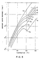
- amalgams For the main amalgam 5, various amalgams are employed whose mercury vapor pressures at the solid and liquid phase coexisting critical temperatures are in the range of 0.01 to 0.2 Torr. Usual critical temperatures of these amalgams are about 80 to 130°C.
- Fig. 5 shows some examples of those amalgams and mercury vapor pressure characteristics thereof.
- the curves I, II, III, IV and V show the vapor pressure curves of the amalgams expressed as Bi(54.2 weight %) ⁇ Pb(41.8 weight %) ⁇ Hg(4.0 weight %), Bi(53.2 weight %) ⁇ Pb(40.9 weight %) ⁇ In(1.9 weight %) ⁇ Hg(4.0 weight %), Bi(51.6 weight %) ⁇ Pb(39.6 weight %) ⁇ In(4.8 weight %) ⁇ Hg(4.0 weight %), Bi(48.9 weight %) ⁇ Pb)37.5 weight %) ⁇ In(9.6 weight %) ⁇ Hg(4.0 weight %) and Bi(64.3 weight %) ⁇ In(31.7 weight %) ⁇ Hg(4.0 weight %) for comparison, respectively and the points C I , C II , C III , C IV and C V indicate the solid and liquid phase coexisting critical temperatures of the amalgams, respectively.
- the curve Hg shows the vapor pressure curve of pure mercury.
- all the solid and liquid phase coexisting critical temperatures C I to C IV of the embodied amalgams I to IV are in the range of 0.01 to 0.2 Torr, while the solid and liquid phase coexisting critical temperatures C V of the amalgam V, the example to be compared with those amalgams is 0.003 (3 x 10 ⁇ 3) Torr.
- the folded portion 14 of the H-shaped type fluorescent lamp embodied in the present invention is specified as above so as to have low cooling capability.
- the folded portion 14 is oriented in a direction where it is affected by gravity and is not affected by convection. This results in that the folded portion 14 is adequately cooled by natural cooling so that a low temperature region is formed on the inner face of the end portion 12.
- the mercury vapor pressure in the tube 1 is controlled by either one of the mercury vapor pressures of the low temperature region or main amalgams whose mercury vapor pressure is close to that of the tube 1.
- the temperature of the main amalgam 5 will be usually higher than that of the folded portion 14, since the main amalgam 5 is located in upper position. This results in the mercury vapor pressure of the main amalgam 5 rising too high to control the mercury vapor pressure in the tube 11. On the contrary, when the ambient temperature rises, the mercury vapor pressure of the main amalgam 5 tends to drop lower than that of pure mercury. This results in the main amalgam 5 controlling the mercury vapor pressure in the tube 11.
- the folded portion 14 When the H-shaped type fluorescent lamp embodied in the present invention is turned on in the base down state, the folded portion 14 is oriented in a direction where it is not affected by gravity and heated by convection. This results in the folded portion 14 not being sufficiently cooled by natural cooling, and the low temperature region is thus formed in the portion such as a tube end portion other than the folded portion 14 and mercury vapor pressure rises too much at the temperature of the low temperature region.
- the solid and liquid phase coexisting critical temperature of the main amalgam 5 is in the range of 0.01 to 0.2 Torr and the main amalgam 5 is oriented in a direction where it is affected by gravity so that the temperature of the main amalgam 5 is comparatively low to have adequate mercury vapor pressure as is understood by Fig. 5. This results in that the mercury vapor pressure in the tube 11 is adequately maintained and mercury does not drop, since the mercury does not condense in the folded portion 14. Furthermore, the mercury vapor pressure in the tube 11 is not to rise too much even if the ambient temperature is too high.
- the fluorescent lamp embodied in the present invention adequately maintains the mercury vapor pressure in the tube 11 even if the ambient temperature fluctuates so that the lamp preferably starts, and maintains a high luminous efficacy without respect to that the lamp is turned on in the base up state or bse down state.
- FIGS. 3 and 4 show an alternative embodiment which is a U-shaped type fluorescent lamp according to the present invention.
- the lamp is characterized in a folded portion 114 of a discharge passage 12, while the other configuration is same as the H-shaped type fluorescent lamp shown in FIG. 1.
- the difference from the H-shaped type fluorescent lamp is only described in detail.
- a bent portion 17 of a tube 10 is formed by bending the intermediate portion of a long longitudinal tube 111 in a U-shape.
- reference numerals each having a same lowest figure or two figures and like letters are used to designate like or equivalent elements for the sake of simplicity of explanation. As is shown in FIG.
- the cooling capability of a folded portion 114 is adequately low.
- the folded portion 14 is positioned in the downward direction so that it is cooled by natural cooling to form a low temperature region in a bent corner portion 18.
- the mercury vapor pressure in the tube 10 is controlled by either the pure mercury in the low temperature region of the main amalgam 15 whose mercury vapor pressure is lower than the other.
- the ambient temperature is a room temperature
- the low temperature region is formed in other than the folded portion 114 so that the temperature does not reach the mercury condensation temperature in the folded portion 114. Owing to the low temperature region being formed in other than the folded portion 114 and the main amalgam 15, the mercury vapor pressure in the tube 10 is adequately maintained by the low temperature region or the main amalgam 15.
- the U-shaped type fluorescent lamp can maintain the mercury vapor pressure in wide range of ambient temperatures, irrespective of it being in the base up state or base down state. Furthermore, the mercury vapor pressure in a tube 10 rarely fluctuates even if the ambient temperature does, so that the lamp has desirable starting characteristic and also a high luminous efficacy.
- each of the folded portions 14 and 114 is geometrically defined in the above two embodiments.
- the condition for the each of the folded portion 14 and 114 is that the low temperature region be formed in the portion adjacent to the each of the folded portion 14 and 114 in the case of the base up state and is not formed in the folded portion 14 in the case of the base down state. If the configuration of the folded portion 14 varies, then the size also varies according to the configuration.
- the reason why the solid and liquid phase coexisting melting point of the main amalgam 5 as the mercury vapor pressure is in the range of 0.01 to 0.2 Torr is as follows. If the amalgam in which mercury tightly condenses is also employed in the base up state, the mercury vapor pressure in a tube is controlled by the main amalgam only to drop too much, so that the low temperature region formed in the folded portion does not function. On the contrary, if the amalgam in which mercury loosely condenses is also employed in the base down state, the amalgam does not adequately control the mercury vapor pressure, so that the mercury vapor pressure in a tube rises too high.
- the discharge passage may be formed in any shape such as a M-shape or a double U-shape if a discharge passage has the configuration such that the two end portions thereof are arranged in the same direction and at least one folded portion is arranged in the opposite direction. Furthermore, this invention may be applied to an ultraviolet discharge lamp.
- the low-pressure mercury vapor discharge lamp according to the present invention is provided such that amalgam is arranged in the end portion of a discharge passage whose two end portions are arranged in the same direction and which has at least one folded portion in the opposite direction and in which a low temperature region is formed in an inner face of a tube adjacent to the folded portion when the lamp is turned on in the state where the folded portion is oriented in a direction where it is affected by gravity, whereas the low temperature region is formed in an inner face of the tube other than the folded portion when the lamp is turned on in the state where the folded portion is oriented in a direction where it is not affected by gravity.
- the amalgam whose mercury vapor pressure is in the range of 0.01 to 0.2 Torr at a solid and liquid coexisting critical temperature is employed.
- the mercury vapor pressure in the tube is controlled by the mercury vapor pressure of either one of the low temperature regions formed in the portion adjacent to the folded portion or the amalgam which is lower than the other when the lamp is turned on in the base up state.
- the mercury vapor pressure in the tube is controlled in such a way that a low temperature region formed in other than the folded portion of amalgam controls the density of mercury. Owing to that, the mercury vapor pressure is adequately maintained over a wide temperature range for both cases, and in addition, a preferable starting characteristic and luminous efficacy are obtained. Furthermore, mercury does not drop even if the lamp is turned on in the base down state.
- Claims 2 an 3 disclose the structure of the folded portion defined numerically so as to obtain the above mentioned effect in a H-shaped and U-shaped low pressure mercury vapor discharge lamps, respectively.
Applications Claiming Priority (2)
| Application Number | Priority Date | Filing Date | Title |
|---|---|---|---|
| JP313157/88 | 1988-12-12 | ||
| JP63313157A JPH083997B2 (ja) | 1988-12-12 | 1988-12-12 | 低圧水銀蒸気放電灯 |
Publications (2)
| Publication Number | Publication Date |
|---|---|
| EP0373567A1 true EP0373567A1 (de) | 1990-06-20 |
| EP0373567B1 EP0373567B1 (de) | 1994-06-15 |
Family
ID=18037797
Family Applications (1)
| Application Number | Title | Priority Date | Filing Date |
|---|---|---|---|
| EP89122851A Revoked EP0373567B1 (de) | 1988-12-12 | 1989-12-11 | Quecksilberdampf-Niederdruckentladungslampe |
Country Status (5)
| Country | Link |
|---|---|
| US (1) | US5055738A (de) |
| EP (1) | EP0373567B1 (de) |
| JP (1) | JPH083997B2 (de) |
| KR (1) | KR920003360B1 (de) |
| DE (1) | DE68916199T2 (de) |
Cited By (4)
| Publication number | Priority date | Publication date | Assignee | Title |
|---|---|---|---|---|
| WO1993018542A1 (en) * | 1992-03-13 | 1993-09-16 | Flowil International Lighting (Holding) B.V. | Low pressure mercury vapor discharge lamp containing an amalgam |
| EP0569814A1 (de) * | 1992-05-13 | 1993-11-18 | Patent-Treuhand-Gesellschaft für elektrische Glühlampen mbH | Niederdruckentladungslampe |
| EP0608205A1 (de) * | 1993-01-20 | 1994-07-27 | Lumalampan Aktiebolag | Kompakte Leuchtstoffröhre |
| EP0758795A1 (de) * | 1995-08-14 | 1997-02-19 | General Electric Company | Amalgamenthaltende kompakte Leuchtstofflampe mit verbessertem Anwärmen |
Families Citing this family (15)
| Publication number | Priority date | Publication date | Assignee | Title |
|---|---|---|---|---|
| US5204584A (en) * | 1990-09-28 | 1993-04-20 | Toshiba Lighting & Technology Corporation | Low pressure mercury vapor discharge lamp |
| US5387837A (en) * | 1992-03-27 | 1995-02-07 | U.S. Philips Corporation | Low-pressure discharge lamp and luminaire provided with such a lamp |
| CN1083148C (zh) * | 1994-12-20 | 2002-04-17 | 皇家菲利浦电子有限公司 | 低压汞汽放电灯 |
| DE19512129A1 (de) * | 1995-03-31 | 1996-10-02 | Patent Treuhand Ges Fuer Elektrische Gluehlampen Mbh | Niederdruckquecksilberdampfentladungslampe |
| CA2177108C (en) * | 1996-05-22 | 2002-10-22 | Minoru Myojo | Low pressure mercury vapor filled discharge lamp |
| US5717290A (en) * | 1996-09-26 | 1998-02-10 | Osram Sylvania Inc. | Starting flag structure for tubular low pressure discharge lamps |
| HU218642B (hu) * | 1996-12-30 | 2000-10-28 | General Electric Co | Egyoldalon fejelt kisülőlámpa |
| DE69921427T2 (de) * | 1998-05-22 | 2006-02-16 | Koninklijke Philips Electronics N.V. | Niederdruckquecksilberdampfentladungslampe |
| US7928644B1 (en) * | 2000-08-22 | 2011-04-19 | General Electric Company | Low pressure discharge lamp with envelope having double helix shape and sealed ends |
| JP3528794B2 (ja) * | 2000-12-20 | 2004-05-24 | 松下電器産業株式会社 | 蛍光ランプ |
| JP2004518247A (ja) * | 2001-01-15 | 2004-06-17 | コーニンクレッカ フィリップス エレクトロニクス エヌ ヴィ | 蛍光ランプ及びその製造方法 |
| KR20020080787A (ko) * | 2001-04-17 | 2002-10-26 | 강성진 | 3차원 구조를 갖는 무전극 형광 램프 |
| DE102004018104A1 (de) * | 2004-04-14 | 2005-11-10 | Patent-Treuhand-Gesellschaft für elektrische Glühlampen mbH | Gasentladungslampe mit Helixform des Entladungsrohres und innerem Rohrstück |
| ES2388643T3 (es) * | 2007-12-14 | 2012-10-17 | Koninklijke Philips Electronics N.V. | Dispositivo de generación de luz atenuable |
| JP7248954B2 (ja) * | 2019-08-29 | 2023-03-30 | 岩崎電気株式会社 | 低圧水銀ランプユニット |
Citations (4)
| Publication number | Priority date | Publication date | Assignee | Title |
|---|---|---|---|---|
| EP0061758A2 (de) * | 1981-03-31 | 1982-10-06 | Patent-Treuhand-Gesellschaft für elektrische Glühlampen mbH | Quecksilberdampf-Niederdruckentladungslampe und Verfahren zur Herstellung |
| US4694215A (en) * | 1984-09-05 | 1987-09-15 | Patent-Treuhand Gesellschaft Fur Elektrische Gluhlampen Mbh | Compact, single-ended fluorescent lamp with fill vapor pressure control |
| US4786841A (en) * | 1987-06-22 | 1988-11-22 | Gte Products Corporation | Low-pressure arc discharge lamp having increased surface brightness |
| EP0327346A2 (de) * | 1988-02-02 | 1989-08-09 | Kabushiki Kaisha Toshiba | Amalgam zur Verwendung in einer Niederdruckquecksilberentladungslampe |
Family Cites Families (15)
| Publication number | Priority date | Publication date | Assignee | Title |
|---|---|---|---|---|
| NL168367C (nl) * | 1975-06-20 | 1982-03-16 | Philips Nv | Lagedrukkwikdampontladingslamp en werkwijze voor de vervaardiging hiervan. |
| NL185479C (nl) * | 1979-04-03 | 1990-04-17 | Philips Nv | Lagedrukgasontladingslamp. |
| DD205772A1 (de) * | 1982-02-16 | 1984-01-04 | Reinhard Butz | Niederdruckgasentladungslampe, insbesondere leuchtstofflampe kleiner leistung |
| EP0151647B1 (de) * | 1983-08-12 | 1991-01-02 | Mitsubishi Denki Kabushiki Kaisha | Herstellungsverfahren einer niederdruck-quecksilberdampf-bogenlampe |
| US4530710A (en) * | 1983-10-24 | 1985-07-23 | Gte Products Corporation | Low-pressure arc discharge lamp having parallel discharge tubes with an arc-containing interconnecting channel; and method of manufacturing same |
| DE8333920U1 (de) * | 1983-11-25 | 1985-05-02 | Patent-Treuhand-Gesellschaft für elektrische Glühlampen mbH, 8000 München | Kompakte niederdruckentladungslampe |
| NL8400756A (nl) * | 1984-03-09 | 1985-10-01 | Philips Nv | Lagedrukkwikdampontladingslamp. |
| NL8401030A (nl) * | 1984-04-02 | 1985-11-01 | Philips Nv | Lagedrukkwikdampontladingslamp. |
| HU192640B (en) * | 1984-12-18 | 1987-06-29 | Tungsram Reszvenytarsasag | Low-power, low-pressure, compact execution mercury-vapour discharge lamp and method for making thereof |
| JPS61230256A (ja) * | 1985-04-03 | 1986-10-14 | Matsushita Electronics Corp | 螢光ランプ |
| SE457033B (sv) * | 1985-05-23 | 1988-11-21 | Lumalampan Ab | Kompaktlysroer |
| SE457761B (sv) * | 1985-05-23 | 1989-01-23 | Lumalampan Ab | Kompaktlysroer |
| JPH0746598B2 (ja) * | 1986-05-29 | 1995-05-17 | 東芝ライテック株式会社 | 蛍光ランプ |
| JPS6386341A (ja) * | 1986-09-30 | 1988-04-16 | Matsushita Electronics Corp | 片口金形蛍光ランプ |
| JPS6489850A (en) * | 1987-09-30 | 1989-04-05 | Toshiba Corp | Private branch exchange |
-
1988
- 1988-12-12 JP JP63313157A patent/JPH083997B2/ja not_active Expired - Fee Related
-
1989
- 1989-12-11 DE DE68916199T patent/DE68916199T2/de not_active Expired - Fee Related
- 1989-12-11 EP EP89122851A patent/EP0373567B1/de not_active Revoked
- 1989-12-12 KR KR1019890018331A patent/KR920003360B1/ko not_active IP Right Cessation
- 1989-12-12 US US07/448,839 patent/US5055738A/en not_active Expired - Lifetime
Patent Citations (4)
| Publication number | Priority date | Publication date | Assignee | Title |
|---|---|---|---|---|
| EP0061758A2 (de) * | 1981-03-31 | 1982-10-06 | Patent-Treuhand-Gesellschaft für elektrische Glühlampen mbH | Quecksilberdampf-Niederdruckentladungslampe und Verfahren zur Herstellung |
| US4694215A (en) * | 1984-09-05 | 1987-09-15 | Patent-Treuhand Gesellschaft Fur Elektrische Gluhlampen Mbh | Compact, single-ended fluorescent lamp with fill vapor pressure control |
| US4786841A (en) * | 1987-06-22 | 1988-11-22 | Gte Products Corporation | Low-pressure arc discharge lamp having increased surface brightness |
| EP0327346A2 (de) * | 1988-02-02 | 1989-08-09 | Kabushiki Kaisha Toshiba | Amalgam zur Verwendung in einer Niederdruckquecksilberentladungslampe |
Non-Patent Citations (1)
| Title |
|---|
| PATENT ABSTRACTS OF JAPAN, unexamined applications, E field, vol. 12, no. 168, May 20, 1988 THE PATENT OFFICE JAPANESE GOVERNMENT page 150 E 611 * |
Cited By (5)
| Publication number | Priority date | Publication date | Assignee | Title |
|---|---|---|---|---|
| WO1993018542A1 (en) * | 1992-03-13 | 1993-09-16 | Flowil International Lighting (Holding) B.V. | Low pressure mercury vapor discharge lamp containing an amalgam |
| EP0569814A1 (de) * | 1992-05-13 | 1993-11-18 | Patent-Treuhand-Gesellschaft für elektrische Glühlampen mbH | Niederdruckentladungslampe |
| EP0608205A1 (de) * | 1993-01-20 | 1994-07-27 | Lumalampan Aktiebolag | Kompakte Leuchtstoffröhre |
| EP0758795A1 (de) * | 1995-08-14 | 1997-02-19 | General Electric Company | Amalgamenthaltende kompakte Leuchtstofflampe mit verbessertem Anwärmen |
| CN1097295C (zh) * | 1995-08-14 | 2002-12-25 | 通用电气公司 | 低压水银蒸气放电灯 |
Also Published As
| Publication number | Publication date |
|---|---|
| DE68916199D1 (de) | 1994-07-21 |
| US5055738A (en) | 1991-10-08 |
| EP0373567B1 (de) | 1994-06-15 |
| JPH083997B2 (ja) | 1996-01-17 |
| DE68916199T2 (de) | 1995-01-19 |
| JPH02158051A (ja) | 1990-06-18 |
| KR900010901A (ko) | 1990-07-11 |
| KR920003360B1 (ko) | 1992-04-30 |
Similar Documents
| Publication | Publication Date | Title |
|---|---|---|
| EP0373567B1 (de) | Quecksilberdampf-Niederdruckentladungslampe | |
| EP0758795B1 (de) | Amalgamenthaltende kompakte Leuchtstofflampe | |
| JPH11513189A (ja) | 簡素化された始動補助部材を具える高圧直列アーク放電ランプ構造体 | |
| US6815889B2 (en) | High-pressure gas discharge lamp | |
| US4633136A (en) | High-pressure discharge lamp with low power input | |
| EP0645800B1 (de) | Hochdruck-Entladungslampe | |
| US4625149A (en) | Metal vapor discharge lamp including an inner burner having tapered ends | |
| US4636687A (en) | Electrode alignment and capsule design for single-ended low wattage metal halide lamps | |
| US4342938A (en) | Universal burning ceramic lamp | |
| US6617790B2 (en) | Metal halide lamp with ceramic discharge vessel | |
| EP0180199B1 (de) | Metallhalogenidentladungslampe mit geringer Leistung | |
| US4620130A (en) | Electrode alignment and capsule design for single-ended low wattage metal halide lamps | |
| US5138218A (en) | Metal vapor discharge lamp having single end arc tube of predetermined thickness | |
| EP0165587B1 (de) | Metallhalogenid-Entladungslampe mit Vorrichtung zum Ausgleich der Bogenrohrtemperatur | |
| US4147952A (en) | Method of sealing alumina arc tube | |
| US4721887A (en) | Metal halide arc lamp having pinch seal with elongated space | |
| EP0159009B1 (de) | Stromkreisunterbrecher mit dünnwandiger Kapsel | |
| US3806748A (en) | Sodium vapor lamp having a grooved alumina arc tube with side rod heater retainer | |
| JP3687779B2 (ja) | 蛍光ランプ | |
| JP3257422B2 (ja) | 高圧放電ランプ | |
| JP3275768B2 (ja) | 高圧金属蒸気放電ランプ | |
| EP0122052B1 (de) | Verfahren zur Herstellung einer Bogenentladungsröhre | |
| US4754198A (en) | Fluorescent lamp bimetal switch contact arrangement | |
| KR20010041165A (ko) | 전기 램프 | |
| JP3888559B2 (ja) | 蛍光ランプおよび照明器具 |
Legal Events
| Date | Code | Title | Description |
|---|---|---|---|
| PUAI | Public reference made under article 153(3) epc to a published international application that has entered the european phase |
Free format text: ORIGINAL CODE: 0009012 |
|
| 17P | Request for examination filed |
Effective date: 19891215 |
|
| AK | Designated contracting states |
Kind code of ref document: A1 Designated state(s): DE GB |
|
| 17Q | First examination report despatched |
Effective date: 19920619 |
|
| GRAA | (expected) grant |
Free format text: ORIGINAL CODE: 0009210 |
|
| AK | Designated contracting states |
Kind code of ref document: B1 Designated state(s): DE GB |
|
| REF | Corresponds to: |
Ref document number: 68916199 Country of ref document: DE Date of ref document: 19940721 |
|
| PLBI | Opposition filed |
Free format text: ORIGINAL CODE: 0009260 |
|
| 26 | Opposition filed |
Opponent name: OSRAM GMBH FI/PATENTWESEN Effective date: 19950315 |
|
| PLBO | Opposition rejected |
Free format text: ORIGINAL CODE: EPIDOS REJO |
|
| PGFP | Annual fee paid to national office [announced via postgrant information from national office to epo] |
Ref country code: GB Payment date: 19971202 Year of fee payment: 9 |
|
| APAC | Appeal dossier modified |
Free format text: ORIGINAL CODE: EPIDOS NOAPO |
|
| APAE | Appeal reference modified |
Free format text: ORIGINAL CODE: EPIDOS REFNO |
|
| PGFP | Annual fee paid to national office [announced via postgrant information from national office to epo] |
Ref country code: DE Payment date: 19971222 Year of fee payment: 9 |
|
| APAC | Appeal dossier modified |
Free format text: ORIGINAL CODE: EPIDOS NOAPO |
|
| PG25 | Lapsed in a contracting state [announced via postgrant information from national office to epo] |
Ref country code: GB Free format text: LAPSE BECAUSE OF NON-PAYMENT OF DUE FEES Effective date: 19981211 |
|
| GBPC | Gb: european patent ceased through non-payment of renewal fee |
Effective date: 19981211 |
|
| PG25 | Lapsed in a contracting state [announced via postgrant information from national office to epo] |
Ref country code: DE Free format text: LAPSE BECAUSE OF NON-PAYMENT OF DUE FEES Effective date: 19991001 |
|
| APAE | Appeal reference modified |
Free format text: ORIGINAL CODE: EPIDOS REFNO |
|
| APAC | Appeal dossier modified |
Free format text: ORIGINAL CODE: EPIDOS NOAPO |
|
| PLAW | Interlocutory decision in opposition |
Free format text: ORIGINAL CODE: EPIDOS IDOP |
|
| RDAH | Patent revoked |
Free format text: ORIGINAL CODE: EPIDOS REVO |
|
| RDAG | Patent revoked |
Free format text: ORIGINAL CODE: 0009271 |
|
| STAA | Information on the status of an ep patent application or granted ep patent |
Free format text: STATUS: PATENT REVOKED |
|
| 27W | Patent revoked |
Effective date: 20030411 |
|
| APAH | Appeal reference modified |
Free format text: ORIGINAL CODE: EPIDOSCREFNO |