EP0372345A2 - Lichtquelle - Google Patents
Lichtquelle Download PDFInfo
- Publication number
- EP0372345A2 EP0372345A2 EP89121851A EP89121851A EP0372345A2 EP 0372345 A2 EP0372345 A2 EP 0372345A2 EP 89121851 A EP89121851 A EP 89121851A EP 89121851 A EP89121851 A EP 89121851A EP 0372345 A2 EP0372345 A2 EP 0372345A2
- Authority
- EP
- European Patent Office
- Prior art keywords
- higher harmonic
- collimator lens
- secondary higher
- light
- light source
- Prior art date
- Legal status (The legal status is an assumption and is not a legal conclusion. Google has not performed a legal analysis and makes no representation as to the accuracy of the status listed.)
- Granted
Links
Images


Classifications
-
- G—PHYSICS
- G02—OPTICS
- G02B—OPTICAL ELEMENTS, SYSTEMS OR APPARATUS
- G02B27/00—Optical systems or apparatus not provided for by any of the groups G02B1/00 - G02B26/00, G02B30/00
- G02B27/42—Diffraction optics, i.e. systems including a diffractive element being designed for providing a diffractive effect
- G02B27/4233—Diffraction optics, i.e. systems including a diffractive element being designed for providing a diffractive effect having a diffractive element [DOE] contributing to a non-imaging application
- G02B27/4244—Diffraction optics, i.e. systems including a diffractive element being designed for providing a diffractive effect having a diffractive element [DOE] contributing to a non-imaging application in wavelength selecting devices
-
- G—PHYSICS
- G02—OPTICS
- G02B—OPTICAL ELEMENTS, SYSTEMS OR APPARATUS
- G02B27/00—Optical systems or apparatus not provided for by any of the groups G02B1/00 - G02B26/00, G02B30/00
- G02B27/42—Diffraction optics, i.e. systems including a diffractive element being designed for providing a diffractive effect
- G02B27/4294—Diffraction optics, i.e. systems including a diffractive element being designed for providing a diffractive effect in multispectral systems, e.g. UV and visible
-
- G—PHYSICS
- G02—OPTICS
- G02F—OPTICAL DEVICES OR ARRANGEMENTS FOR THE CONTROL OF LIGHT BY MODIFICATION OF THE OPTICAL PROPERTIES OF THE MEDIA OF THE ELEMENTS INVOLVED THEREIN; NON-LINEAR OPTICS; FREQUENCY-CHANGING OF LIGHT; OPTICAL LOGIC ELEMENTS; OPTICAL ANALOGUE/DIGITAL CONVERTERS
- G02F1/00—Devices or arrangements for the control of the intensity, colour, phase, polarisation or direction of light arriving from an independent light source, e.g. switching, gating or modulating; Non-linear optics
- G02F1/35—Non-linear optics
- G02F1/37—Non-linear optics for second-harmonic generation
- G02F1/377—Non-linear optics for second-harmonic generation in an optical waveguide structure
- G02F1/383—Non-linear optics for second-harmonic generation in an optical waveguide structure of the optical fibre type
-
- G—PHYSICS
- G02—OPTICS
- G02B—OPTICAL ELEMENTS, SYSTEMS OR APPARATUS
- G02B27/00—Optical systems or apparatus not provided for by any of the groups G02B1/00 - G02B26/00, G02B30/00
- G02B27/42—Diffraction optics, i.e. systems including a diffractive element being designed for providing a diffractive effect
- G02B27/4233—Diffraction optics, i.e. systems including a diffractive element being designed for providing a diffractive effect having a diffractive element [DOE] contributing to a non-imaging application
- G02B27/425—Diffraction optics, i.e. systems including a diffractive element being designed for providing a diffractive effect having a diffractive element [DOE] contributing to a non-imaging application in illumination systems
Definitions
- the present invention is directed to a light source device capable of creating secondary higher harmonic waves and in turn transforming the waves into parallel beams of light.
- the secondary higher harmonic waves are generated using laser beams passed through a secondary higher harmonic wave generating element.
- the secondary higher harmonic waves radiate from the photo waveguide unit having a given width towards the substrate, so that there are no desirable wave surface characteristics are exhibited.
- the secondary higher harmonic waves are composed of groups of parallel beams of light showing a surface symmetry, and hence there is such a defect that the beams of light can not be converged at a small spot.
- the secondary higher harmonic wave generating element of the optical fiber type exhibits an axial symmetry, and therefore these secondary higher harmonic waves are expanded in a ring-like configuration. It is expected that favorable convergence characteristics are provided.
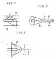
- the secondary higher harmonic waves emerging from the secondary higher harmonic wave generating element of the optical fiber type have equi-phase surfaces each assuming a conical shape.
- FIGURE 8 depicts this feature.
- the secondary higher harmonic waves expand to form conical beam via a clad 42 of an optical fiber 4.
- a conical collimator lens 50 can be employed.
- the conical collimator lens 50 Since the conical collimator lens 50 has a considerable thickness, it is difficult to apply to a small-sized light source device and the handling and adjustment thereof are inconvenient and cumbersome. An additional problem is that the light source device can not satisfactorily be miniaturized.
- a non-linear optical effect may be understood as a phenomenon wherein polarization is proportional to terms having a higher-order than the square of the electric field of the light incident upon a medium. This phenomenon permits generation of the secondary higher harmonic waves by the medium.
- Non-linear optical element An element having such a medium is referred to as a non-linear optical element.
- Inorganic materials such as KH2PO4, LiNbO3 and the like are often utilized.
- Much attention has recently been paid to organic materials represented by 2-methyl-4-nitroaniline (MNA), because these materials have a large non-linear optical constant.
- MNA 2-methyl-4-nitroaniline
- the secondary higher harmonic wave generating element for use comes under a photo waveguide type.
- An arrangement of the photo waveguide type is that an elongated photo waveguide unit through which the light travels while being confined therein is formed on a substrate, and an overlayer is convered thereon.
- a photo waveguide path is required to have a structure adaptable to a propagation phase velocity of the secondary higher harmonic waves in order to propagate the secondary higher waves generated in the photo waveguide unit or the like. Namely, the photo waveguide path has to match in phase with the secondary higher harmonic waves.
- a wide variety of methods are available for obtaining this phase conformity. The simplest method of obtaining the phase conformity may involve the use of the Cerenkov radiation system.
- the Cerenkov radiation system is arranged in such a way that if the secondary higher harmonic waves, which are, as illustrated in FIGURE 7, generated from the light travelling through a photo waveguide unit 11 at a point A, leak into an overlayer 13 as well as into a substrate 12 at an angle ⁇ , the secondary higher harmonic waves radiate in a range defined by the angle ⁇ when equi-phase surfaces of the secondary higher harmonic waves again leak in a ⁇ -direction at a point B after a unit time has passed coinciding with equi-phase surfaces of the above-mentioned secondary higher harmonic waves.
- n s (w) be a refraction factor of the substrate 12 or the overlayer 13 to fundamental waves
- n G (w) be a refraction factor of the waveguide unit 11
- n s (2w) be a refraction factor of the substrate 12 or the overlayer 13 to the secondary higher harmonic waves.
- the phase conformity can automatically be attained and the Cerenkov radiation can also be effected on a condition that the following requirement is satisfied: n s (2w) > n G (w) > n s (w)
- the Cerenkov radiation is adopted as a system capable of obtaining the phase conformity in the simplest manner.
- a light source device comprising a laser light source, an optical fiber type secondary higher harmonic wave generating element for generating secondary higher harmonic waves by admitting incident of laser beams emitted from the laser light source, and a collimator lens for converting the secondary higher harmonic waves emerging from the secondary higher harmonic wave generating element into parallel beams of light.
- the collimator lens has an annular diffraction lattice pattern arranged such that respective oblique surfaces of diffraction lattices are formed in concentric circles at equal spacings, the oblique surfaces partially constituting side surfaces of a plurality of conical bodies concentric with the concentric circles.
- the laser beams emitted from the laser source are led to the optical fiber type secondary higher harmonic wave generating element, wherein the secondary higher harmonic waves are generated.
- the secondary higher harmonic waves are changed into waves exhibiting an axial symmetry and having equi-phase surfaces each assuming a conical shape, thus expanding from an end surface of an optical fiber.
- the secondary higher harmonic waves When causing the secondary higher harmonic waves to pass through a plurality of diffraction lattices concentrically disposed at equal spacings, the secondary higher harmonic waves are converted into parallel beams of light of a predetermined degree by diffractive action of the diffraction lattices.
- respective oblique surfaces of the diffraction lattices constitute side surfaces of the conical bodies, whereby the parallel beams of light radiate in a well-separated state from beams of light of other degrees.
- FIGURE 1 there is illustrated a light source device composed of: a laser light source 1 such as a semiconductor laser or the like; a spherical lens 2 for collimating laser beams emitted from the laser light source 1; a condensing spherical lens 3 for condensing the parallel beams of light; an optical fiber type secondary higher harmonic wave generating element 4 including a core 41 formed of a known non-linear optical material such as an MNA and a clad 42 formed of glass; and a Fresnel collimator lens 5 for collimating the secondary higher harmonic waves generated from the optical fiber type secondary higher harmonic wave generating element 4.
- a laser light source 1 such as a semiconductor laser or the like
- a condensing spherical lens 3 for condensing the parallel beams of light
- an optical fiber type secondary higher harmonic wave generating element 4 including a core 41 formed of a known non-linear optical material such as an MNA and a clad 42 formed of glass
- An optical axis of the Fresnel collimator lens is disposed to coincide with a symmetric axis of the optical fiber type secondary higher harmonic wave generating element 4.
- An arrangement of the Fresnel collimator lens 5 is that a thin glass substrate is, as illustrated in FIGURE 2, concentrically incised with a plurality of annular diffraction lattices having pitch d. Oblique surfaces 51 of the diffraction lattices are rectilinearly shaped to respectively have a given angle as shown in FIGURE 2(b) cut along a central axis 52 of the concentric circle.
- the oblique surfaces 51 are arranged to partially constitute side surfaces of these conical bodies, wherein ⁇ is the angle made by the oblique surface 51 of the diffraction lattice and by the central axis 52.
- the secondary higher harmonic waves emerging from the optical fiber type secondary higher harmonic wave generating element 4 are, as depicted in FIGURE 3(a), incident on the Fresnel collimator lens 5 at a given angle ⁇ o to a symmetric axis (major axis) of the optical fiber 4, thereby generating, as illustrated in FIGURE 3(b), lst, 0th, -1st and -2nd diffractive beams of light by means of diffraction.
- the parallel beams of light can be emitted from the Fresnel collimator lens 5.
- These beams of light are condensed by a well-known condensing means, thus obtaining a small spot which substantially matches with a light wavelength limit.
- the Fresnel collimator lens 5 is constructed by forming the annular lattices on the glass substrate and can therefore be formed thin without difficulty. In addition to this advantage, the collimator lens 5 enables miniaturization of the light source device as a whole.
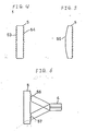
- the Fresnel collimator lens 5 is not limited to the above-described configuration.
- the collimator lens may assume such a configuration that diffraction lattice patterns 53 and 54 are, as depicted in FIGURE 4, provided on both surfaces of the lens.
- the pitch d of the diffraction lattice can be widened.
- this in turn facilitates processing of the diffraction lattices and is conducive to an improvement of processing accuracy.
- One surface may be formed, as illustrated in FIGURE 5, in a spherical shape 55, thereby obtaining an optical element in which the diffraction lattices for collimating the beams of light and a convex lens for condensing the beams of light are combined.
- the diffraction lattices are not necessarily provided on the entire surface of the Fresnel collimator lens 5. As shown in FIGURE 6, the pattern may be formed only on portions 56 and 57 which admit the secondary higher harmonic waves. A variety of modifications in design can be effected without departing from the essence of the present invention.
- the optical fiber type secondary higher harmonic wave generating element emits the secondary higher harmonic waves that exhibit axial symmetry and have conical equi-phase surfaces.
- the secondary higher harmonic waves pass through the Fresnel collimator lens having the diffraction lattice pattern in which the diffraction lattices are concentrically formed at equal spacings, and the oblique surfaces thereof constitute the side surfaces of a plurality of conical bodies, the central axis of which is common to that of the concentric circles.
- the beams of light can be converged to a small spot, and the collimator lens can also be formed thin.
- the present invention has an application particularly as a small-sized light source device.
Applications Claiming Priority (2)
| Application Number | Priority Date | Filing Date | Title |
|---|---|---|---|
| JP63307611A JPH02153328A (ja) | 1988-12-05 | 1988-12-05 | 光源装置 |
| JP307611/88 | 1988-12-05 |
Publications (3)
| Publication Number | Publication Date |
|---|---|
| EP0372345A2 true EP0372345A2 (de) | 1990-06-13 |
| EP0372345A3 EP0372345A3 (en) | 1990-10-31 |
| EP0372345B1 EP0372345B1 (de) | 1994-04-06 |
Family
ID=17971120
Family Applications (1)
| Application Number | Title | Priority Date | Filing Date |
|---|---|---|---|
| EP89121851A Expired - Lifetime EP0372345B1 (de) | 1988-12-05 | 1989-11-27 | Lichtquelle |
Country Status (5)
| Country | Link |
|---|---|
| US (1) | US5058981A (de) |
| EP (1) | EP0372345B1 (de) |
| JP (1) | JPH02153328A (de) |
| CA (1) | CA2004634C (de) |
| DE (1) | DE68914414T2 (de) |
Cited By (1)
| Publication number | Priority date | Publication date | Assignee | Title |
|---|---|---|---|---|
| EP0377988A2 (de) * | 1989-01-13 | 1990-07-18 | Kabushiki Kaisha Toshiba | Optische Wellenlängenkonverter-Einrichtung |
Families Citing this family (22)
| Publication number | Priority date | Publication date | Assignee | Title |
|---|---|---|---|---|
| US5114513A (en) * | 1988-10-27 | 1992-05-19 | Omron Tateisi Electronics Co. | Optical device and manufacturing method thereof |
| JP2878701B2 (ja) * | 1989-01-13 | 1999-04-05 | 株式会社東芝 | 波長変換光学素子 |
| US5172369A (en) * | 1990-03-02 | 1992-12-15 | Pioneer Electronic Corporation | Optical pickup, optical information recording carrier and recording and reproducing apparatus thereof |
| JP2788777B2 (ja) * | 1990-03-02 | 1998-08-20 | パイオニア株式会社 | 光ピックアップ |
| JPH03287140A (ja) * | 1990-04-02 | 1991-12-17 | Pioneer Electron Corp | レーザー光波長変換装置 |
| JPH04215622A (ja) * | 1990-12-14 | 1992-08-06 | Sumitomo Electric Ind Ltd | 光源装置 |
| US5293444A (en) * | 1990-12-14 | 1994-03-08 | Sumitomo Electric Industries, Ltd. | Wavelength converter |
| DE4213910A1 (de) * | 1991-05-03 | 1992-11-05 | Minnesota Mining & Mfg | Holographiespiegel mit superzonen |
| US5148317A (en) * | 1991-06-24 | 1992-09-15 | The United States Of America As Represented By The Secretary Of The Air Force | Diffractive optical element for collimating and redistributing Gaussian input beam |
| US5420719A (en) * | 1993-09-15 | 1995-05-30 | Lumonics Inc. | Laser beam frequency doubling system |
| US5636915A (en) * | 1993-11-12 | 1997-06-10 | General Electric Company | High brightness projection lighting system |
| US5566024A (en) * | 1993-12-23 | 1996-10-15 | Xerox Corporation | Beam separation control and beam splitting by single blazed binary diffraction optical element |
| US5606434A (en) * | 1994-06-30 | 1997-02-25 | University Of North Carolina | Achromatic optical system including diffractive optical element |
| DK0803075T3 (da) * | 1995-01-11 | 2003-03-31 | Ullmann Christoph Dr | Optisk anordning til anvendelse i et laserdiodesystem |
| JP2002329935A (ja) * | 2001-05-07 | 2002-11-15 | Toshiba Corp | レーザ光源装置、レーザ装置、レーザ出射方法およびレーザ光源装置の製造方法 |
| KR100453040B1 (ko) * | 2002-02-01 | 2004-10-15 | 삼성전자주식회사 | 콜리메이팅 렌즈, 콜리메이팅 시스템 및 이를 채용한 화상표시장치 |
| CA2460856C (en) * | 2003-05-09 | 2011-09-20 | Donald R. Klein | Helicopter moving device |
| US20060100907A1 (en) * | 2003-10-07 | 2006-05-11 | Holland Geoffrey N | Medication management system |
| CN101939699B (zh) * | 2008-02-19 | 2012-09-05 | 日本碍子株式会社 | 高次谐波发生器 |
| DE102011008192A1 (de) * | 2011-01-10 | 2012-07-12 | Limo Patentverwaltung Gmbh & Co. Kg | Vorrichtung zur Umwandlung von Laserstrahlung in Laserstahlung mit einem M-Profil |
| US9431788B2 (en) * | 2014-04-21 | 2016-08-30 | Ofs Fitel, Llc | Mode converter for high power, higher-order mode optical fiber amplifiers |
| US9733485B2 (en) | 2015-10-30 | 2017-08-15 | Himax Technologies Limited | Collimating lens |
Citations (3)
| Publication number | Priority date | Publication date | Assignee | Title |
|---|---|---|---|---|
| US2759393A (en) * | 1952-10-25 | 1956-08-21 | Eastman Kodak Co | Optical aligners employing axicons |
| JPS6315235A (ja) * | 1986-07-08 | 1988-01-22 | Fuji Photo Film Co Ltd | 光波長変換素子 |
| JPS6333716A (ja) * | 1986-07-29 | 1988-02-13 | Omron Tateisi Electronics Co | 光整形装置 |
Family Cites Families (18)
| Publication number | Priority date | Publication date | Assignee | Title |
|---|---|---|---|---|
| BE789176A (fr) * | 1971-09-24 | 1973-01-15 | Siemens Ag | Dispositif pour l'introduction et l'extraction de lumiere dans des guides d'ondes optiques dielectriques et procede pour sa fabrication |
| US4050782A (en) * | 1975-04-21 | 1977-09-27 | Nippon Electric Company, Ltd. | Mode separator and delay equalizer for multimode optical fiber transmission systems |
| US4178066A (en) * | 1976-05-10 | 1979-12-11 | Cselt Centro Studi E Laboratori Telecomunicazioni S.P.A. | Ray-path equalizer for signal-transmission system using multimode light guides |
| US4077701A (en) * | 1976-06-02 | 1978-03-07 | International Telephone And Telegraph Corporation | Method and arrangements for dispersion equalization of optical fiber transmission lines |
| JPS54110851A (en) * | 1978-02-17 | 1979-08-30 | Mitsubishi Electric Corp | Coupling system of optical transmission line |
| US4389085A (en) * | 1978-02-22 | 1983-06-21 | Kei Mori | Lighting system utilizing the sunlight |
| JPS5571918A (en) * | 1978-11-25 | 1980-05-30 | Ritsuo Hasumi | Rod lens type photo wave meter |
| JPS57161841A (en) * | 1981-03-31 | 1982-10-05 | Canon Inc | Focusing glass |
| JPS62212608A (ja) * | 1986-03-14 | 1987-09-18 | Mitsubishi Rayon Co Ltd | 光フアイバ−用コリメ−タ−素子 |
| JPS63199328A (ja) * | 1987-02-16 | 1988-08-17 | Fuji Photo Film Co Ltd | 光波長変換素子 |
| JPH01105220A (ja) * | 1987-07-20 | 1989-04-21 | Fuji Photo Film Co Ltd | 光波長変換素子 |
| US4909596A (en) * | 1987-09-14 | 1990-03-20 | Fuji Photo Film Co., Ltd. | Optical wavelength converter module |
| JPH0820654B2 (ja) * | 1987-11-02 | 1996-03-04 | 富士写真フイルム株式会社 | 光波長変換素子 |
| JPH01293326A (ja) * | 1988-05-20 | 1989-11-27 | Pioneer Electron Corp | ファイバー型光波長変換装置 |
| JP2686536B2 (ja) * | 1988-05-20 | 1997-12-08 | パイオニア株式会社 | ファイバー型光波長変換装置 |
| JP2525879B2 (ja) * | 1988-10-14 | 1996-08-21 | パイオニア株式会社 | ファイバ―型光波長変換素子 |
| US4900129A (en) * | 1988-12-16 | 1990-02-13 | Minnesota Mining And Manufacturing Company | Dual grooved Fresnel lens for overhead projection |
| US4919511A (en) * | 1989-02-03 | 1990-04-24 | Pioneer Electronic Corporation | Fibre-type light conversion device |
-
1988
- 1988-12-05 JP JP63307611A patent/JPH02153328A/ja active Pending
-
1989
- 1989-11-27 DE DE68914414T patent/DE68914414T2/de not_active Expired - Fee Related
- 1989-11-27 EP EP89121851A patent/EP0372345B1/de not_active Expired - Lifetime
- 1989-12-04 US US07/444,934 patent/US5058981A/en not_active Expired - Fee Related
- 1989-12-05 CA CA002004634A patent/CA2004634C/en not_active Expired - Fee Related
Patent Citations (3)
| Publication number | Priority date | Publication date | Assignee | Title |
|---|---|---|---|---|
| US2759393A (en) * | 1952-10-25 | 1956-08-21 | Eastman Kodak Co | Optical aligners employing axicons |
| JPS6315235A (ja) * | 1986-07-08 | 1988-01-22 | Fuji Photo Film Co Ltd | 光波長変換素子 |
| JPS6333716A (ja) * | 1986-07-29 | 1988-02-13 | Omron Tateisi Electronics Co | 光整形装置 |
Non-Patent Citations (2)
| Title |
|---|
| PATENT ABSTRACTS OF JAPAN, vol. 12, no. 220 (P-720)[3067], 23rd June 1988; & JP-A-63 15 235 (FUJI PHOTO FILM CO., LTD) 22-01-1988 * |
| PATENT ABSTRACTS OF JAPAN, vol. 12, no. 243 (P-728)[3090], 9th July 1988; & JP-A-63 33 716 (OMRON TATEISI ELECTRONICS CO.) 13-02-1988 * |
Cited By (3)
| Publication number | Priority date | Publication date | Assignee | Title |
|---|---|---|---|---|
| EP0377988A2 (de) * | 1989-01-13 | 1990-07-18 | Kabushiki Kaisha Toshiba | Optische Wellenlängenkonverter-Einrichtung |
| EP0377988A3 (de) * | 1989-01-13 | 1991-09-11 | Kabushiki Kaisha Toshiba | Optische Wellenlängenkonverter-Einrichtung |
| US5377291A (en) * | 1989-01-13 | 1994-12-27 | Kabushiki Kaisha Toshiba | Wavelength converting optical device |
Also Published As
| Publication number | Publication date |
|---|---|
| JPH02153328A (ja) | 1990-06-13 |
| CA2004634C (en) | 1997-10-21 |
| EP0372345A3 (en) | 1990-10-31 |
| DE68914414D1 (de) | 1994-05-11 |
| CA2004634A1 (en) | 1990-06-05 |
| US5058981A (en) | 1991-10-22 |
| DE68914414T2 (de) | 1994-07-28 |
| EP0372345B1 (de) | 1994-04-06 |
Similar Documents
| Publication | Publication Date | Title |
|---|---|---|
| US5058981A (en) | Light source device | |
| JPH0412039B2 (de) | ||
| JPH01293326A (ja) | ファイバー型光波長変換装置 | |
| EP0360122B1 (de) | Generator für die zweite Harmonische und denselben benutzendes Informationssystem | |
| US5046817A (en) | Generation of parallel second harmonic light rays using an optical fiber | |
| JP2686536B2 (ja) | ファイバー型光波長変換装置 | |
| CA2057545C (en) | Light source device | |
| US5416877A (en) | Optical wavelength converter device and optical wavelength converter module | |
| JPH02125233A (ja) | ファイバー型光波長変換装置 | |
| US5112122A (en) | Fiber-type light conversion device | |
| JPH0820621B2 (ja) | プリンタ用放射源 | |
| JPH03166531A (ja) | ファイバー型光波長変換装置 | |
| JPH01293325A (ja) | ファイバー型光波長変換器 | |
| JPS63269131A (ja) | 平行光作成装置 | |
| EP0490369B1 (de) | Wellenlängen-Konverter | |
| JPH0545656U (ja) | 光源装置 | |
| JPH02205828A (ja) | ファイバー型光波長変換装置 | |
| JPH0215434A (ja) | 光ピックアップ | |
| JPH0235424A (ja) | 光波長変換素子 | |
| JPH02125234A (ja) | ファイバー型光波長変換装置 | |
| JPS58132716A (ja) | 光ビ−ム径変換装置 | |
| JPH03157828A (ja) | 光ピックアップ装置 | |
| Hatakoshi et al. | Grating lenses for optical components | |
| JPH01279433A (ja) | 光ピックアップ | |
| JPH02212821A (ja) | ファイバー型光波長変換装置 |
Legal Events
| Date | Code | Title | Description |
|---|---|---|---|
| PUAI | Public reference made under article 153(3) epc to a published international application that has entered the european phase |
Free format text: ORIGINAL CODE: 0009012 |
|
| AK | Designated contracting states |
Kind code of ref document: A2 Designated state(s): DE FR GB |
|
| PUAL | Search report despatched |
Free format text: ORIGINAL CODE: 0009013 |
|
| AK | Designated contracting states |
Kind code of ref document: A3 Designated state(s): DE FR GB |
|
| 17P | Request for examination filed |
Effective date: 19901212 |
|
| 17Q | First examination report despatched |
Effective date: 19920722 |
|
| GRAA | (expected) grant |
Free format text: ORIGINAL CODE: 0009210 |
|
| AK | Designated contracting states |
Kind code of ref document: B1 Designated state(s): DE FR GB |
|
| REF | Corresponds to: |
Ref document number: 68914414 Country of ref document: DE Date of ref document: 19940511 |
|
| ET | Fr: translation filed | ||
| PLBE | No opposition filed within time limit |
Free format text: ORIGINAL CODE: 0009261 |
|
| STAA | Information on the status of an ep patent application or granted ep patent |
Free format text: STATUS: NO OPPOSITION FILED WITHIN TIME LIMIT |
|
| 26N | No opposition filed | ||
| PGFP | Annual fee paid to national office [announced via postgrant information from national office to epo] |
Ref country code: FR Payment date: 19971112 Year of fee payment: 9 |
|
| PGFP | Annual fee paid to national office [announced via postgrant information from national office to epo] |
Ref country code: GB Payment date: 19971118 Year of fee payment: 9 |
|
| PGFP | Annual fee paid to national office [announced via postgrant information from national office to epo] |
Ref country code: DE Payment date: 19971205 Year of fee payment: 9 |
|
| PG25 | Lapsed in a contracting state [announced via postgrant information from national office to epo] |
Ref country code: GB Free format text: LAPSE BECAUSE OF NON-PAYMENT OF DUE FEES Effective date: 19981127 |
|
| GBPC | Gb: european patent ceased through non-payment of renewal fee |
Effective date: 19981127 |
|
| PG25 | Lapsed in a contracting state [announced via postgrant information from national office to epo] |
Ref country code: FR Free format text: LAPSE BECAUSE OF NON-PAYMENT OF DUE FEES Effective date: 19990730 |
|
| REG | Reference to a national code |
Ref country code: FR Ref legal event code: ST |
|
| PG25 | Lapsed in a contracting state [announced via postgrant information from national office to epo] |
Ref country code: DE Free format text: LAPSE BECAUSE OF NON-PAYMENT OF DUE FEES Effective date: 19990901 |