EP0367000B1 - Vorrichtung zum Sichern der sichtbaren Schlüsselöffnung bei Schlössern - Google Patents
Vorrichtung zum Sichern der sichtbaren Schlüsselöffnung bei Schlössern Download PDFInfo
- Publication number
- EP0367000B1 EP0367000B1 EP89119120A EP89119120A EP0367000B1 EP 0367000 B1 EP0367000 B1 EP 0367000B1 EP 89119120 A EP89119120 A EP 89119120A EP 89119120 A EP89119120 A EP 89119120A EP 0367000 B1 EP0367000 B1 EP 0367000B1
- Authority
- EP
- European Patent Office
- Prior art keywords
- mounting
- pin
- pins
- lock
- protective
- Prior art date
- Legal status (The legal status is an assumption and is not a legal conclusion. Google has not performed a legal analysis and makes no representation as to the accuracy of the status listed.)
- Expired - Lifetime
Links
Images


Classifications
-
- E—FIXED CONSTRUCTIONS
- E05—LOCKS; KEYS; WINDOW OR DOOR FITTINGS; SAFES
- E05B—LOCKS; ACCESSORIES THEREFOR; HANDCUFFS
- E05B17/00—Accessories in connection with locks
- E05B17/14—Closures or guards for keyholes
- E05B17/142—Closures or guards for keyholes with key-operated locks, e.g. padlocks
-
- E—FIXED CONSTRUCTIONS
- E05—LOCKS; KEYS; WINDOW OR DOOR FITTINGS; SAFES
- E05B—LOCKS; ACCESSORIES THEREFOR; HANDCUFFS
- E05B27/00—Cylinder locks or other locks with tumbler pins or balls that are set by pushing the key in
- E05B27/0028—Other locks than cylinder locks with tumbler pins or balls
Definitions
- the invention relates to a device for securing the visible key insertion opening in locks that have a fitting associated with the key insertion opening, above which a protective fitting covering the key insertion opening is arranged, which is slidably held on the fitting on guides on the edge, the protective fitting using a lock with the Fitting is connectable.
- a device with these features is known (DE-U-87 01 771), the known protective fitting being provided with a magnetically coded lock which has a bolt which projects beyond the inner surface of the protective fitting in the closed state and which interacts with a counter-locking part arranged in the fitting.
- This lock can be released by actuating the magnetic lock and the protective fitting can be removed from the key insertion opening.
- the main disadvantage of this device is that this security fitting does not provide sufficient security for the mortise lock, because the security fitting can be rendered ineffective by simple means.
- the lock can also be outsmarted, for example, by inserting a thin film between the protective fitting and the fitting, with which the only bolt can be pushed up.
- Another disadvantage is that such a magnetic lock has few locking options, which significantly affects security. By fitting the devices of such a magnetic lock, the protective fitting has a large overall height.
- the invention has for its object to provide a device of the type mentioned in such a way that a high level of security with regard to the closing differences is ensured while avoiding the destructibility of the protective device.
- the lock has locking pins which are arranged vertically to the plane between the fitting and the protective fitting and are supported on springs in the fitting and that the locking pins are divided into upper and lower pins, in the open position of the lock, the contact surfaces between the upper and lower pins coincide with the level between the protective fitting and the fitting and that each locking pin consists of the centrally arranged upper and lower pins and an upper and lower sleeve arranged coaxially therewith, the upper and lower pins on the Inner wall of the upper and lower sleeve is guided.
- An advantageous embodiment consists in that the upper pin has a cylindrical widening which, in the closed position, bears against an inner contact shoulder of the upper sleeve, the upper pin toward the closing side and the upper sleeve coincides with the surface of the protective fitting.
- a spacer ring is provided between the upper sleeve and the lower sleeve, which is arranged in the open position of the lock with its underside in the plane of division between the protective fitting and the fitting, a spiral spring between the cylindrical widening of the pin and the spacer ring is provided.
- spiral springs arranged coaxially to one another be provided on the underside of the lower part of the pin and the lower sleeve.
- a combination lock is attached to the protective fitting, which has rotating pins assigned to the locking pins.
- the invention has the essential advantage that the lock provided has a high locking variant, which is also associated with a correspondingly high level of security.
- the special design of the locking pins results in a smaller space requirement for the arrangement of the locking pins while maintaining the same number of locking options.
- the device is also suitable for a locking system, since the pins can be divided.
- the invention has a high protection against violent removal of the entire locking device.
- This design also prevents the ingress of dust or glue, and in the case of a combination lock, the glue can be easily removed by turning the rotating pins several times.
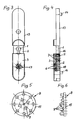
- a two-part fitting 2 is shown, which consists of an upper fitting part 13 and an adjoining lower fitting part 18.
- a protective fitting 3 is slidably held on the lower fitting part 18 on guides 16 on the edge, such a guide groove being visible in FIG. 4.
- Fastening sleeves 14 are used to attach the fitting 2.
- the lower fitting part 18 assigned to the protective fitting 3 is provided with a specially designed lock 12, with individual locking pins 4 being arranged in these two parts 3, 18 in accordance with a regularly or irregularly designed hole pattern 17.
- These locking pins 4 run vertically to the plane between the lower fitting part 18 of the fitting 2 and the protective fitting 3.
- the pins 4 are further subdivided into lower pins 7, which are predominantly arranged in the lower fitting part 18, and upper pins 6, the lower pins 7 being connected to springs 5 support in part 18.
- the upper pins 6 have a part of smaller diameter, which then merges into a part with a larger diameter.
- the pins 4 are supported on the collar 20 within the protective fitting 3.
- the lower pins 7 pass through the sliding plane 19 between the protective fitting 3 and the lower fitting part 18, the upper pins 6, the lower part of which has the same diameter as the lower pins 7, with the spring pressure of the springs 5 Collar 20 are supported.
- the parts of the upper pins 6 which have the smaller diameter are located on the surface of the protective fitting 3.
- the key shown in FIGS. 5 and 6 is used to actuate the lock 12.
- This key consists of a disc 15 on which 17 individual confirmation pins 9 are arranged in accordance with the hole pattern.
- the length of these actuating pins 9 is matched to the locking pins 4, the individual locking pins 4 being pushed back so far when the key 8 is put on and pressed in that all the divisional levels between the upper and lower pins 6, 7 are in the sliding plane 19.
- the protective fitting 3 can then be pulled down.
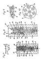
- FIGS. 9 and 10 show the exemplary embodiment of a key 8, which has seven actuating pins 9 on a disk 15 having.
- the locking pins 4 serve to secure a protective fitting 3 to a fitting 2 and penetrate the sliding or dividing plane 19 between the fittings 2, 3 vertically.
- Each locking pin 4 consists of a two-part central pin 6, 7 and a two-part sleeve 23, 24 arranged over this pin 6, 7, which is guided on the pin 6, 7.
- the upper part 6 of the pin is provided with a cylindrical widening 25 which is guided on the inside of the upper part 23 of the sleeve.
- the upper part 23 of the sleeve rests with a shoulder 20 within the protective fitting 3 such that the end face of the sleeve 23 coincides with the surface 28 of the protective fitting 3.
- a spacer ring 29 adjoins the underside of the upper part 23 of the sleeve, which is provided with a step 33 relative to the upper part 23 of the sleeve and engages in a corresponding step of the upper part 23.
- the lower part 24 of the sleeve connects to the underside 30 of the spacer ring 29.
- a spiral spring 31 which presses the upper part 6 of the pin against an abutment shoulder 26 in the upper part 23 of the sleeve, so that the upper part 23 of the sleeve and the upper part 6 of the pin both in the closed state ( Fig. 7) as well as the opened state (Fig. 8) of the lock with the surface 28 viewed from the closing side 27, coincide.
- On the underside of the locking pin 4 there is a spring 5 for the pin 6, 7 and coaxially with a spring 32 for the sleeve 23, 24.
- the confirmation pins 9 of the key 8 are designed in two stages and have an attachment 34 of smaller diameter and an attachment 35 with a larger diameter for actuating the pin 6, 7 or the sleeve 23, 24.
- FIG. 7 shows the locking pin in the closed position, the lower part 24 of the sleeve and the lower part 7 of the pin penetrating the parting plane 19 between the fittings 2, 3.
- the actuating pins 9 move the sleeve 23, 24 or the pins 6, 7 so far that their parting plane lies within the parting plane 19 of the fittings 2, 3.
- This parting plane is located on the underside 30 of the spacer ring 29 to the lower part 24 of the sleeve and the upper part 6 or lower part 7 of the pin.
- This open position is shown in FIG. 8.
- FIGS. 11 and 12 show a further embodiment for the design of the lock in connection with a combination lock, the housing 10 of such a combination lock being fastened on the outside of the protective fitting 3.
- this housing 10 there are individual pivot pins 11, such a pivot pin 11 being assigned to each locking pin 4.
- the locking pins 4 protrude with their upper pins 6 into the interior 21 of the housing 10 and rest on a widened head 22 of the pivot pins 11.
- the rotary movement of the pivot pins 11 can be based on a combination of numbers, the locking pins 4 coming into their open position by correspondingly screwing these pins in.
Landscapes
- Lock And Its Accessories (AREA)
- Casings For Electric Apparatus (AREA)
- Closures For Containers (AREA)
Description
- Die Erfindung betrifft eine Vorrichtung zum Sichern der sichtbaren Schlüsseleinstecköffnung bei Schlössern, die einen der Schlüsseleinstecköffnung zugeordneten Beschlag aufweisen, über dem ein die Schlüsseleinstecköffnung abdeckender Schutzbeschlag angeordnet ist, der an dem Beschlag an randseitigen Führungen verschiebbar gehalten wird, wobei der Schutzbeschlag mittels eines Schlosses mit dem Beschlag verbindbar ist.
- Eine Vorrichtung mit diesen Merkmalen ist bekannt (DE-U-87 01 771), wobei der bekannte Schutzbeschlag mit einem magnetisch codierten Schloß versehen ist, das einen die Innenfläche des Schutzbeschlages im Schließzustand überragenden Riegel aufweist, der mit einem im Beschlag angeordneten Gegenschließteil zusammenwirkt. Durch Betätigen des Magnetschlosses kann dieser Riegel freigegeben werden und es läßt sich der Schutzbeschlag von der Schlüsseleinstecköffnung entfernen. Der wesentliche Nachteil dieser Einrichtung besteht darin, daß dieser Schutzbeschlag keine ausreichende Sicherung des Einsteckschlosses darstellt, weil der Schutzbeschlag mit einfachen Mitteln unwirksam gemacht werden kann. Das Schloß kann beispielsweise auch dadurch einfach überlistet werden, indem zwischen Schutzbeschlag und Beschlag eine dünne Folie eingeschoben wird, mit der der einzige Riegel hochgedrückt werden kann. Ein weiterer Nachteil besteht darin, daß ein derartiges Magnetschloß wenig Schließmöglichkeiten hat, wodurch die Sicherheit erheblich beeinträchtigt ist. Durch die Unterbringung der Einrichtungen eines derartigen Magnetschlosses besitzt der Schutzbeschlag eine große Bauhöhe.
- Bekannt ist weiterhin ein drehbarer Riegel (US-A-40 06 616), bei dem Schließstifte verwendet werden, die in Ober- und Unterstifte geteilt sind. Durch Einstekken eines entsprechenden Schlüssels werden diese Stifte derart verschoben, daß ihre Teilungsebene mit der Teilungsebene im Schloß zusammenfällt, so daß der Riegel betätigt werden kann. Der wesentliche Nachteil dieser bekannten Einrichtung besteht darin, als zum Erreichen einer notwendigen hohen Schließvariante ein verhältnismäßig großer Platzbedarf erforderlich ist, um sämtliche Stifte unterzubringen.
- Der Erfindung liegt die Aufgabe zugrunde, eine Vorrichtung der eingangs genannten Art so auszubilden, daß bei Vermeidung der Zerstörbarkeit der Schutzeinrichtung eine hohe Sicherheit im Hinblick auf die Schließverschiedenheiten gewährleistet ist.
- Diese Aufgabe wird nach der Erfindung dadurch gelöst, daß das Schloß Schließstifte aufweist, die vertikal zur Ebene zwischen dem Beschlag und dem Schutzbeschlag angeordnet sind und sich an Federn im Beschlag abstützen und daß die Schließstifte in Ober- und Unterstifte geteilt sind, wobei in der Öffnungsstellung des Schlosses die Anlageflächen zwischen Ober- und Unterstift mit der Ebene zwischen dem Schutzbeschlag und dem Beschlag zusammenfällt und daß jeder Schließstift aus dem zentral angeordneten Ober- und Unterstift und einer dazu koaxial angeordneten Ober- und Unterhülse besteht, wobei der Ober- und Unterstift an der Innenwandung der Ober- und Unterhülse geführt ist.
- Eine vorteilhafte Ausführungsform besteht darin, daß der Oberstift eine zylindrische Verbreiterung aufweist, die in der Schließstellung an einer inneren Anlageschulter der Oberhülse anliegt, wobei zur Schließseite hin der Oberstift und die Oberhülse mit der Oberfläche des Schutzbeschlages zusammenfällt.
- Weiterhin ist es vorteilhaft, daß zwischen der Oberhülse und der Unterhülse ein Distanzscheibenring vorgesehen ist, der in der Öffnungsstellung des Schlosses mit seiner Unterseite in der Teilungsebene zwischen dem Schutzbeschlag und dem Beschlag angeordnet ist, wobei zwischen der zylindrischen Verbreiterung des Stiftes und dem Distanzscheibenring eine Spiralfeder vorgesehen ist.
- Weiterhin wird vorgeschlagen, daß an der Unterseite des Stiftunterteiles und der Unterhülse koaxial zueinander angeordnete Spiralfedern vorgesehen sind.
- Es ist vorteilhaft, daß auf dem Schutzbeschlag ein Zahlenschloß angebracht ist, das den Schließstiften zugeordnete Drehstifte aufweist.
- Die Erfindung bringt den wesentlichen Vorteil, daß das vorgesehene Schloß eine hohe Schließvariante aufweist, womit auch eine entsprechend hohe Sicherheit verbunden ist. Durch die besondere Ausbildung der Schließstifte ergibt sich ein geringerer Platzbedarf für die Anordnung der Schließstifte unter Erhaltung der gleichen Anzahl von Schließmöglichkeiten. Die Vorrichtung ist weiterhin geeignet für eine Schließanlage, da die Stifte unterteilbar sind. Die Erfindung weist einen hohen Schutz gegen ein gewaltsames Entfernen der gesamten Schließvorrichtung auf.
- Durch diese Bauweise ist auch ein Eindringen von Staub oder Klebstoff nicht möglich, wobei bei einem Zahlenschloß der Klebstoff durch mehrmaliges Verdrehen der Drehstifte leicht entfernt werden kann.
- Die Erfindung wird in der nachfolgenden Beschreibung anhand von in den Zeichnungen dargestellten Ausführungsbeispielen näher erläutert.
- Es zeigen,
- Fig. 1
- eine Ausführungsform der erfindungsgemäßen Vorrichtung im Aufriß,
- Fig. 2
- eine Seitenansicht von Fig. 1, teilweise im Schnitt,
- Fig. 3
- die Vorrichtung im Aufriß bei teilweise geöffnetem Schutsbeschlag,
- Fig. 4
- eine Seitenansicht von Fig. 3, teilweise im Schnitt,
- Figuren 5 und 6
- den vorgesehenen Schlüssel im Auf- und Seitenriß,
- Fig. 7
- einen Schnitt durch einen Schließstift eines derartigen Schlosses im abgesperrten Zusatand gemäß einer weiteren Ausführungsform,
- Fig. 8
- einen derartigen Schließstift in der Öffnungsstellung,
- Figuren 9 und 10
- einen Schlüssel zum Betätigen des Schlosses nach den Fig. 7 und 8 im Auf- und Grundriß,
- Fig. 11
- eine weitere Ausführungsform der Vorrichtung im Aufriß,
- Fig. 12
- eine Seitenansicht von Fig. 11, teilweise geschnitten.
- Bei der in den Figuren 1 bis 4 dargestellten Ausführungsform der Vorrichtung ist ein zweiteiliger Beschlag 2 dargestellt, der aus einem Beschlagoberteil 13 und einem daran unmittelbar anschließenden Bechlagunterteil 18 besteht. Im Bereich dieses Beschlagunterteiles befindet sich eine sichtbare Schlüsseleinstecköffnung 1 eines Einsteckschlosses, die mit Hilfe eines Schutzbeschlages 3 abgedeckt ist. Dieser Schutzbeschlag 3 ist an dem Beschlagunterteil 18 verschiebbar an randseitigen Führungen 16 gehalten, wobei eine derartige Führungsnut in Fig. 4 sichtbar ist. Zum Anbringen des Beschlages 2 dienen Befestigungshülsen 14.
Das dem Schutzbeschlag 3 zugeordnete Beschlagunterteil 18 ist mit einem besonders ausgebildeten Schloß 12 versehen, wobei entsprechend einem regelmäßig oder unregelmäßig ausgebildeten Lochbild 17 einzelne Schließstifte 4 in diesen beiden Teilen 3, 18 angeordnet sind. Diese Schließstifte 4 verlaufen vertikal zur Ebene zwischen dem Beschlagunterteil 18 des Beschlages 2 und dem Schutzbeschlag 3. Die Stifte 4 sind weiterhin unterteilt in Unterstifte 7, die vorwiegend im Beschlagunterteil 18 angeordnet sind, und Oberstifte 6, wobei sich die Unterstifte 7 an Federn 5 im Teil 18 abstützen. Die Oberstifte 6 besitzen einen Teil geringeren Durchmessers, der dann in einen Teil mit einem größeren Durchmesser übergeht. An diesem Kragen 20 stützen sich die Stifte 4 innerhalb des Schutzbeschlages 3 ab. Im Schließzustand (Fig. 1 und 2) durchqueren die Unterstifte 7 die Gleitebene 19 zwischen dem Schutzbeschlag 3 und dem Beschlagunterteil 18, wobei durch den Federdruck der Federn 5 auch die Oberstifte 6, deren Unterteil den gleichen Durchmesser aufweist wie die Unterstifte 7, mit ihrem Kragen 20 abgestützt sind. Die den geringeren Durchmesser aufweisenden Teile der Oberstifte 6 befinden sich hierbei an der Oberfläche des Schutzbeschlages 3. - Zum Betätigen des Schlosses 12 dient der in den Figuren 5 und 6 dargestellte Schlüssel. Dieser Schlüssel besteht aus einer Scheibe 15, an der entsprechend dem Lochbild 17 einzelne Bestätigungsstifte 9 angeordnet sind. Die Länge dieser Betätigungsstifte 9 ist auf die Schließstifte 4 abgestimmt, wobei beim Aufsetzen und Eindrücken des Schlüssels 8 die einzelnen Schließstifte 4 so weit zurückgedrückt werden, daß sich sämtliche Teilungsebenen zwischen Ober- und Unterstift 6,7 in der Gleitebene 19 befinden. Der Schutzbeschlag 3 kann dann nach unten abgezogen werden.
- Gemäß der Ausführungsform nach den Figuren 7 bis 10 ist ein Schließstift 4 eines derartigen Schlosses dargestellt, wobei zu einem derartigen Schloß mehrere solcher Schließstifte gehören. In den Figuren 9 und 10 ist das Ausführungsbeispiel eines Schlüssels 8 dargestellt, der an einer Scheibe 15 sieben Betätigungsstifte 9 aufweist. Die Schließstifte 4 dienen zur Sicherung eines Schutzbeschlages 3 an einem Beschlag 2 und durchdringen die Gleit- bzw. Teilungsebene 19 zwischen den Beschlägen 2,3 senkrecht.
- Jeder Schließstift 4 besteht aus einem zweiteiligen zentralen Stift 6,7 und einer über diesen Stift 6,7 angeordneten zweiteiligen Hülse 23,24, die an dem Stift 6,7 geführt ist. Das Oberteil 6 des Stiftes ist mit einer zylindrischen Verbreiterung 25 versehen, die an der Innenseite des Oberteils 23 der Hülse geführt ist. Das Oberteil 23 der Hülse liegt mit einer Schulter 20 innerhalb des Schutzbeschlages 3 derart an, daß die Stirnfläche der Hülse 23 mit der Oberfläche 28 des Schutzbeschlages 3 zusammenfällt. An die Unterseite des Oberteiles 23 der Hülse schließt ein Distanzscheibenring 29 an, der zum Oberteil 23 der Hülse mit einer Abstufung 33 versehen ist und in eine entsprechende Abstufung des Oberteils 23 eingreift. An der Unterseite 30 des Distanzscheibenringes 29 schließt das Unterteil 24 der Hülse an. Zwischen dem Distanzscheibenring 29 und der zylindrischen Verbreiterung 25 befindet sich eine Spiralfeder 31, die das Oberteil 6 des Stiftes gegen eine Anlageschulter 26 im Oberteil 23 der Hülse drückt, so daß das Oberteil 23 der Hülse und das Oberteil 6 des Stiftes sowohl im abgeschlossenen Zustand (Fig. 7) als auch geöffneten Zustand (Fig. 8) des Schlosses mit der Oberfläche 28 von der Schließseite 27 aus betrachtet, zusammenfallen. An der Unterseite des Schließstiftes 4 befindet sich eine Feder 5 für den Stift 6,7 und koaxial dazu eine Feder 32 für die Hülse 23,24.
- Die Bestätigungsstifte 9 des Schlüssels 8 sind zweistufig ausgebildet und besitzen einen Aufsatz 34 geringeren Durchmessers und einen Aufsatz 35 mit größerem Durchmesser zum Betätigen des Stiftes 6,7 bzw. der Hülse 23,24.
- Die Figur 7 zeigt den Schließstift in der Schließstellung, wobei das Unterteil 24 der Hülse und das Unterteil 7 des Stiftes die Teilungsebene 19 zwischen den Beschlägen 2,3 durchdringt. Beim Aufsetzen des Schlüssels werden durch die Betätigungsstifte 9 die Hülse 23,24 bzw. die Stifte 6, 7 so weit verschoben, daß sie mit ihrer Trennebene innerhalb der Teilungsebene 19 der Beschläge 2,3 liegen. Diese Trennebene befindet sich an der Unterseite 30 des Distanzscheibenringes 29 zum Unterteil 24 der Nülse sowie dem Oberteil 6, bzw. Unterteil 7 des Stiftes. Diese Öffnungsstellung zeigt die Figur 8. Beim Abnehmen des Schlüssels 8 wird das Oberteil 6 des Stiftes und das Oberteile 23 der Hülse durch die Feder 31 zur Anlage an die Schultern 20,26 so weit nach oben gedrückt, daß die Oberseiten der Teile 23,6 mit der Oberfläche 28 des Schutzbeschlages 3 zusamenfällt.
- Damit ergeben sich bei der gleichen Anzahl von Schließmöglichkeiten weniger Stifte, d.h. es wird die Hälfte derartiger Stifte gebraucht. Hierbei wird auch die Sicherheit des Schlosses dahingehend gewährleistet, als eine Erkennung der Schließung im geöffneten Zustand nicht möglich ist.
- Die Figuren 11 und 12 zeigen eine weitere Ausführungsform für die Ausgestaltung des Schlosses in Verbindung mit einem Zahlenschloß, wobei außen auf dem Schutzbeschlag 3 das Gehäuse 10 eines derartigen Zahlenschlosses befestigt ist. In diesem Gehäuse 10 befinden sich einzelne Drehstifte 11, wobei jedem Schließstift 4 ein derartiger Drehstift 11 zugeordnet ist. Hierbei ragen die Schließstifte 4 mit ihren Oberstiften 6 in den Innenraum 21 des Gehäuses 10 und liegen an einem verbreiterten Kopf 22 der Drehstifte 11 an. Der Drehbewegung der Drehstifte 11 kann hierbei eine Zahlenkombination zugrundegelegt werden, wobei durch ein entsprechendes Hineindrehen dieser Stifte die Schließstifte 4 in ihre Öffnungsstellung gelangen.
Claims (5)
- Vorrichtung zum Sichern der sichtbaren Schlüsseleinstecköffnung (1) bei Schlössern, die einen der Schlüsseleinstecköffnung (1) zugeordneten Beschlag (2) aufweisen, über dem ein die Schlüsseleinstecköffnung (1) abdeckender Schutzbeschlag (3) angeordnet ist, der an dem Beschlag (2) an randseitigen Führungen verschiebbar gehalten wird, wobei der Schutzbeschlag (3) mittels eines Schlosses (12) mit dem Beschlag (2) verbindbar ist, dadurch gekennzeichnet, daß das Schloß (12) Schließstifte (4) aufweist, die vertikal zur Ebene zwischen dem Beschlag (2) und dem Schutzbeschlag (3) angeordnet sind und sich an Federn (5) im Beschlag (2) abstützen und daß die Schließstifte (4) in Ober- und Unterstifte (6,7) geteilt sind, wobei in der Öffnungsstellung des Schlosses (12) die Anlageflächen zwischen Ober- und Unterstift (6,7) mit der Ebene (19) zwischen dem Schutzbeschlag (3) und dem Beschlag (2) zusammenfällt und daß jeder Schließstift (4) aus dem zentral angeordneten Ober- und Unterstift (6,7) und einer dazu koaxial angeordneten Ober- und Unterhülse (23,24) besteht, wobei der Ober- und Unterstift (6,7) an der Innenwandung der Ober- und Unterhülse (23,24) geführt ist.
- Vorrichtung nach Anspruch 1, dadurch gekennzeichnet, daß der Oberstift (6) eine zylindrische Verbreiterung (25) aufweist, die in der Schließstellung an einer inneren Anlageschulter (26) der Oberhülse (23) anliegt, wobei zur Schließseite (27) hin der Oberstift (6) und die Oberhülse (23) mit der Oberfläche (28) des Schutzbeschlages (3) zusammenfällt.
- Vorrichtung nach Anspruch 1 und 2, dadurch gekennzeichnet, daß zwischen der Oberhülse (23) und der Unterhülse (24) ein Distanzscheibenring (29) vorgesehen ist, der in der Öffnungsstellung des Schlosses mit seiner Unterseite (30) in der Teilungsebene (19) zwischen dem Schutzbeschlag (3) und dem Beschlag (2) angeordnet ist, wobei zwischen der zylindrischen Verbreiterung (25) des Stiftes und dem Distanzscheibenring (29) eine Spiralfeder (31) vorgesehen ist.
- Vorrichtung nach Anspruch 1 bis 3, dadurch gekennzeichnet, daß an der Unterseite des Stiftunterteiles (7) und der Unterhülse (24) koaxial zueinander angeordnete Spiralfedern (5,32) vorgesehen sind.
- Vorrichtung nach Anspruch 1 bis 4, dadurch gekennzeichnet, daß auf dem Schutzbeschlag (3) ein Zahlenschloß (10) angebracht ist, das den Schließstiften (4) zugeordnete Drehstifte (11) aufweist.
Priority Applications (1)
| Application Number | Priority Date | Filing Date | Title |
|---|---|---|---|
| AT89119120T ATE94940T1 (de) | 1988-11-04 | 1989-10-14 | Vorrichtung zum sichern der sichtbaren schluesseloeffnung bei schloessern. |
Applications Claiming Priority (4)
| Application Number | Priority Date | Filing Date | Title |
|---|---|---|---|
| DE19883837427 DE3837427A1 (de) | 1988-11-04 | 1988-11-04 | Vorrichtung zum sichern der sichtbaren schluesseloeffnung bei schloessern |
| DE3837427 | 1988-11-04 | ||
| DE3840128 | 1988-11-29 | ||
| DE3840128A DE3840128A1 (de) | 1988-11-04 | 1988-11-29 | Vorrichtung zum sichern der sichtbaren schluesseloeffnung bei schloessern |
Publications (3)
| Publication Number | Publication Date |
|---|---|
| EP0367000A2 EP0367000A2 (de) | 1990-05-09 |
| EP0367000A3 EP0367000A3 (de) | 1991-07-31 |
| EP0367000B1 true EP0367000B1 (de) | 1993-09-22 |
Family
ID=25873894
Family Applications (1)
| Application Number | Title | Priority Date | Filing Date |
|---|---|---|---|
| EP89119120A Expired - Lifetime EP0367000B1 (de) | 1988-11-04 | 1989-10-14 | Vorrichtung zum Sichern der sichtbaren Schlüsselöffnung bei Schlössern |
Country Status (3)
| Country | Link |
|---|---|
| EP (1) | EP0367000B1 (de) |
| DE (2) | DE3840128A1 (de) |
| ES (1) | ES2046429T3 (de) |
Cited By (2)
| Publication number | Priority date | Publication date | Assignee | Title |
|---|---|---|---|---|
| DE202010015828U1 (de) | 2010-11-24 | 2012-02-27 | Drumm Gmbh | Schutzbeschlag für Fenster |
| RU183068U1 (ru) * | 2017-12-01 | 2018-09-07 | Андрей Николаевич Хорошавин | Автоматическая шторка для накладки замочной скважины сувальдного замка |
Families Citing this family (9)
| Publication number | Priority date | Publication date | Assignee | Title |
|---|---|---|---|---|
| ES2061389B1 (es) * | 1993-01-11 | 1999-01-16 | Cerrajera Ind | Protector para cilindros de cerraduras. |
| DE9402326U1 (de) * | 1994-02-16 | 1994-10-06 | Confon Ag | Sicherheitsschloß zur Sicherung von Bauteile miteinander verbindenden Schrauben und Muttern von Schraubenbolzen |
| JP4160216B2 (ja) * | 1999-09-30 | 2008-10-01 | 本田技研工業株式会社 | 車両のシリンダ錠保護装置 |
| EP1595044B1 (de) * | 2003-02-10 | 2006-10-11 | Kolektor Group Vodenje in Upravljanje Druzb D.O.O. | Schliesszylinder mit schlüssel |
| DE10312269A1 (de) | 2003-03-19 | 2004-09-30 | Drumm Gmbh | Magneto-mechanische Schließeinrichtung |
| DE202005015298U1 (de) * | 2005-09-28 | 2007-02-08 | Drumm Gmbh | Verriegelungseinrichtung |
| ITRM20110299A1 (it) * | 2011-06-14 | 2012-12-15 | Fabio Fontana | Sistema di agganciamento o sganciamento di elementi sovrapponibili. |
| CN109153349B (zh) | 2016-05-18 | 2021-09-14 | 上海延锋金桥汽车饰件系统有限公司 | 用于车辆内部的控制台组件 |
| US11572723B2 (en) | 2019-02-27 | 2023-02-07 | Shanghai Yanfeng Jinqiao Automotive Triim Systems Co. Ltd. | Vehicle interior component |
Family Cites Families (5)
| Publication number | Priority date | Publication date | Assignee | Title |
|---|---|---|---|---|
| DE148608C (de) * | ||||
| CH13834A (fr) * | 1896-12-31 | 1897-08-31 | Virgile Ceruti | Nouvelle fermeture à secret |
| DE327767C (de) * | 1918-12-25 | 1920-10-16 | Johann Huehnel | Schloss mit Stiftzuhaltungen |
| US4006615A (en) * | 1975-08-07 | 1977-02-08 | Janos Szova | Axial tumbler lock |
| DE8701771U1 (de) * | 1987-02-06 | 1988-06-01 | Melchert Beschlaege Gmbh & Co Kg, 5628 Heiligenhaus, De |
-
1988
- 1988-11-29 DE DE3840128A patent/DE3840128A1/de not_active Withdrawn
-
1989
- 1989-10-14 EP EP89119120A patent/EP0367000B1/de not_active Expired - Lifetime
- 1989-10-14 ES ES8989119120T patent/ES2046429T3/es not_active Expired - Lifetime
- 1989-10-14 DE DE89119120T patent/DE58905678D1/de not_active Expired - Fee Related
Cited By (3)
| Publication number | Priority date | Publication date | Assignee | Title |
|---|---|---|---|---|
| DE202010015828U1 (de) | 2010-11-24 | 2012-02-27 | Drumm Gmbh | Schutzbeschlag für Fenster |
| EP2458117A2 (de) | 2010-11-24 | 2012-05-30 | Drumm GmbH | Schutzbeschlag für Fenster |
| RU183068U1 (ru) * | 2017-12-01 | 2018-09-07 | Андрей Николаевич Хорошавин | Автоматическая шторка для накладки замочной скважины сувальдного замка |
Also Published As
| Publication number | Publication date |
|---|---|
| DE3840128A1 (de) | 1990-07-19 |
| ES2046429T3 (es) | 1994-02-01 |
| EP0367000A2 (de) | 1990-05-09 |
| DE58905678D1 (de) | 1993-10-28 |
| EP0367000A3 (de) | 1991-07-31 |
Similar Documents
| Publication | Publication Date | Title |
|---|---|---|
| EP0367000B1 (de) | Vorrichtung zum Sichern der sichtbaren Schlüsselöffnung bei Schlössern | |
| EP0787874A1 (de) | Elektronisches Türschloss | |
| DE19632318A1 (de) | Verriegelungsvorrichtung für Schacht-Innendeckel | |
| EP0555633B1 (de) | Türdrückergarnitur | |
| EP0175049A2 (de) | Steckschlüsselbetätigbarer Vorreiberverschluss | |
| AT404857B (de) | Zylinderschloss mit zylinderkern und zylindergehäuse sowie flachschlüssel | |
| EP0036141B1 (de) | Steckschlüsselbetätigbare Arretierungsvorrichtung | |
| EP0364936A2 (de) | Kraftfahrzeug-Türschloss | |
| EP0453626B1 (de) | Mit Schlosseinrichtung versehener versenkbarer Schwenkhebelverschluss | |
| EP0835975B1 (de) | Schliesszylinder | |
| DE4407678C2 (de) | Schlüsselschalter | |
| DE4244414C2 (de) | Verschluß für Fenster, Türen u. dgl. | |
| DE3837427C2 (de) | ||
| EP3990738A1 (de) | Gehäuse für einen antrieb sowie antrieb | |
| DE19738244C2 (de) | Schloß für Sicherheitstüren | |
| DE8600443U1 (de) | Kraftfahrzeugtür, die eine eingebaute Türverschlußvorrichtung aufweist | |
| DE4400650B4 (de) | Abschließbare Drehbetätigungsvorrichtung für Fenster oder Türen | |
| WO1991017333A1 (de) | Mit schlosseinrichtung versehener versenkbarer schwenkhebelverschluss | |
| DE4107076C2 (de) | Kombinationsschloß mit veränderbarem Schlüsselgeheimnis für Behältnisse, wie Koffer, Aktentaschen od. dgl. | |
| EP0296337B1 (de) | Profilschliesszylinder | |
| EP0861955B1 (de) | Verschliessbarer Fenstergriff | |
| DE3224789A1 (de) | Drucktasten-schaltschloss mit exklusiv-schaltposition | |
| CH664416A5 (de) | Sicherheitsbeschlag. | |
| EP0701034A1 (de) | Schloss für Gefängnistüren | |
| DE8608621U1 (de) | Schließzylinderabdeckung für Türschlösser |
Legal Events
| Date | Code | Title | Description |
|---|---|---|---|
| PUAI | Public reference made under article 153(3) epc to a published international application that has entered the european phase |
Free format text: ORIGINAL CODE: 0009012 |
|
| AK | Designated contracting states |
Kind code of ref document: A2 Designated state(s): AT BE CH DE ES FR GB GR IT LI LU NL SE |
|
| PUAL | Search report despatched |
Free format text: ORIGINAL CODE: 0009013 |
|
| AK | Designated contracting states |
Kind code of ref document: A3 Designated state(s): AT BE CH DE ES FR GB GR IT LI LU NL SE |
|
| 17P | Request for examination filed |
Effective date: 19910715 |
|
| 17Q | First examination report despatched |
Effective date: 19921012 |
|
| GRAA | (expected) grant |
Free format text: ORIGINAL CODE: 0009210 |
|
| AK | Designated contracting states |
Kind code of ref document: B1 Designated state(s): AT BE CH DE ES FR GB GR IT LI LU NL SE |
|
| REF | Corresponds to: |
Ref document number: 94940 Country of ref document: AT Date of ref document: 19931015 Kind code of ref document: T |
|
| ITF | It: translation for a ep patent filed |
Owner name: STUDIO GLP S.R.L. |
|
| REF | Corresponds to: |
Ref document number: 58905678 Country of ref document: DE Date of ref document: 19931028 |
|
| ET | Fr: translation filed | ||
| GBT | Gb: translation of ep patent filed (gb section 77(6)(a)/1977) |
Effective date: 19931102 |
|
| EPTA | Lu: last paid annual fee | ||
| REG | Reference to a national code |
Ref country code: GR Ref legal event code: FG4A Free format text: 3009484 |
|
| REG | Reference to a national code |
Ref country code: ES Ref legal event code: FG2A Ref document number: 2046429 Country of ref document: ES Kind code of ref document: T3 |
|
| PLBE | No opposition filed within time limit |
Free format text: ORIGINAL CODE: 0009261 |
|
| STAA | Information on the status of an ep patent application or granted ep patent |
Free format text: STATUS: NO OPPOSITION FILED WITHIN TIME LIMIT |
|
| 26N | No opposition filed | ||
| EAL | Se: european patent in force in sweden |
Ref document number: 89119120.7 |
|
| REG | Reference to a national code |
Ref country code: GB Ref legal event code: IF02 |
|
| PG25 | Lapsed in a contracting state [announced via postgrant information from national office to epo] |
Ref country code: IT Free format text: LAPSE BECAUSE OF NON-PAYMENT OF DUE FEES;WARNING: LAPSES OF ITALIAN PATENTS WITH EFFECTIVE DATE BEFORE 2007 MAY HAVE OCCURRED AT ANY TIME BEFORE 2007. THE CORRECT EFFECTIVE DATE MAY BE DIFFERENT FROM THE ONE RECORDED. Effective date: 20051014 |
|
| PGFP | Annual fee paid to national office [announced via postgrant information from national office to epo] |
Ref country code: GR Payment date: 20061030 Year of fee payment: 18 |
|
| PGFP | Annual fee paid to national office [announced via postgrant information from national office to epo] |
Ref country code: DE Payment date: 20071206 Year of fee payment: 19 Ref country code: NL Payment date: 20071030 Year of fee payment: 19 Ref country code: ES Payment date: 20071129 Year of fee payment: 19 Ref country code: LU Payment date: 20071016 Year of fee payment: 19 |
|
| PGFP | Annual fee paid to national office [announced via postgrant information from national office to epo] |
Ref country code: CH Payment date: 20071019 Year of fee payment: 19 Ref country code: AT Payment date: 20071017 Year of fee payment: 19 |
|
| PGFP | Annual fee paid to national office [announced via postgrant information from national office to epo] |
Ref country code: SE Payment date: 20071016 Year of fee payment: 19 Ref country code: BE Payment date: 20071119 Year of fee payment: 19 |
|
| PGFP | Annual fee paid to national office [announced via postgrant information from national office to epo] |
Ref country code: FR Payment date: 20071015 Year of fee payment: 19 Ref country code: GB Payment date: 20071018 Year of fee payment: 19 |
|
| BERE | Be: lapsed |
Owner name: SICHERHEIT UND SERVICE INH. KLAUS PETER *DRUMM Effective date: 20081031 |
|
| PG25 | Lapsed in a contracting state [announced via postgrant information from national office to epo] |
Ref country code: GR Free format text: LAPSE BECAUSE OF NON-PAYMENT OF DUE FEES Effective date: 20080505 |
|
| REG | Reference to a national code |
Ref country code: CH Ref legal event code: PL |
|
| EUG | Se: european patent has lapsed | ||
| GBPC | Gb: european patent ceased through non-payment of renewal fee |
Effective date: 20081014 |
|
| NLV4 | Nl: lapsed or anulled due to non-payment of the annual fee |
Effective date: 20090501 |
|
| REG | Reference to a national code |
Ref country code: FR Ref legal event code: ST Effective date: 20090630 |
|
| PG25 | Lapsed in a contracting state [announced via postgrant information from national office to epo] |
Ref country code: NL Free format text: LAPSE BECAUSE OF NON-PAYMENT OF DUE FEES Effective date: 20090501 |
|
| PG25 | Lapsed in a contracting state [announced via postgrant information from national office to epo] |
Ref country code: DE Free format text: LAPSE BECAUSE OF NON-PAYMENT OF DUE FEES Effective date: 20090501 Ref country code: AT Free format text: LAPSE BECAUSE OF NON-PAYMENT OF DUE FEES Effective date: 20081014 |
|
| PG25 | Lapsed in a contracting state [announced via postgrant information from national office to epo] |
Ref country code: BE Free format text: LAPSE BECAUSE OF NON-PAYMENT OF DUE FEES Effective date: 20081031 |
|
| PG25 | Lapsed in a contracting state [announced via postgrant information from national office to epo] |
Ref country code: CH Free format text: LAPSE BECAUSE OF NON-PAYMENT OF DUE FEES Effective date: 20081031 Ref country code: FR Free format text: LAPSE BECAUSE OF NON-PAYMENT OF DUE FEES Effective date: 20081031 Ref country code: LI Free format text: LAPSE BECAUSE OF NON-PAYMENT OF DUE FEES Effective date: 20081031 |
|
| PG25 | Lapsed in a contracting state [announced via postgrant information from national office to epo] |
Ref country code: GB Free format text: LAPSE BECAUSE OF NON-PAYMENT OF DUE FEES Effective date: 20081014 |
|
| REG | Reference to a national code |
Ref country code: ES Ref legal event code: FD2A Effective date: 20081015 |
|
| PG25 | Lapsed in a contracting state [announced via postgrant information from national office to epo] |
Ref country code: ES Free format text: LAPSE BECAUSE OF NON-PAYMENT OF DUE FEES Effective date: 20081015 |
|
| PGFP | Annual fee paid to national office [announced via postgrant information from national office to epo] |
Ref country code: IT Payment date: 20071030 Year of fee payment: 19 |
|
| PGRI | Patent reinstated in contracting state [announced from national office to epo] |
Ref country code: IT Effective date: 20091201 |
|
| PG25 | Lapsed in a contracting state [announced via postgrant information from national office to epo] |
Ref country code: LU Free format text: LAPSE BECAUSE OF NON-PAYMENT OF DUE FEES Effective date: 20081014 |
|
| PG25 | Lapsed in a contracting state [announced via postgrant information from national office to epo] |
Ref country code: SE Free format text: LAPSE BECAUSE OF NON-PAYMENT OF DUE FEES Effective date: 20081015 |
|
| PGRI | Patent reinstated in contracting state [announced from national office to epo] |
Ref country code: IT Effective date: 20091201 |