EP0353527A2 - Dispositif de désempilage d'une palette chargée d'une pile de feuilles de papier - Google Patents
Dispositif de désempilage d'une palette chargée d'une pile de feuilles de papier Download PDFInfo
- Publication number
- EP0353527A2 EP0353527A2 EP19890113030 EP89113030A EP0353527A2 EP 0353527 A2 EP0353527 A2 EP 0353527A2 EP 19890113030 EP19890113030 EP 19890113030 EP 89113030 A EP89113030 A EP 89113030A EP 0353527 A2 EP0353527 A2 EP 0353527A2
- Authority
- EP
- European Patent Office
- Prior art keywords
- separating tongue
- stack
- pallet
- displacement path
- ejector
- Prior art date
- Legal status (The legal status is an assumption and is not a legal conclusion. Google has not performed a legal analysis and makes no representation as to the accuracy of the status listed.)
- Withdrawn
Links
Images


Classifications
-
- B—PERFORMING OPERATIONS; TRANSPORTING
- B65—CONVEYING; PACKING; STORING; HANDLING THIN OR FILAMENTARY MATERIAL
- B65H—HANDLING THIN OR FILAMENTARY MATERIAL, e.g. SHEETS, WEBS, CABLES
- B65H3/00—Separating articles from piles
- B65H3/32—Separating articles from piles by elements, e.g. fingers, plates, rollers, inserted or traversed between articles to be separated and remainder of the pile
- B65H3/322—Separating articles from piles by elements, e.g. fingers, plates, rollers, inserted or traversed between articles to be separated and remainder of the pile for separating a part of the pile, i.e. several articles at once
-
- B—PERFORMING OPERATIONS; TRANSPORTING
- B65—CONVEYING; PACKING; STORING; HANDLING THIN OR FILAMENTARY MATERIAL
- B65H—HANDLING THIN OR FILAMENTARY MATERIAL, e.g. SHEETS, WEBS, CABLES
- B65H1/00—Supports or magazines for piles from which articles are to be separated
- B65H1/08—Supports or magazines for piles from which articles are to be separated with means for advancing the articles to present the articles to the separating device
- B65H1/18—Supports or magazines for piles from which articles are to be separated with means for advancing the articles to present the articles to the separating device controlled by height of pile
-
- B—PERFORMING OPERATIONS; TRANSPORTING
- B65—CONVEYING; PACKING; STORING; HANDLING THIN OR FILAMENTARY MATERIAL
- B65H—HANDLING THIN OR FILAMENTARY MATERIAL, e.g. SHEETS, WEBS, CABLES
- B65H5/00—Feeding articles separated from piles; Feeding articles to machines
- B65H5/02—Feeding articles separated from piles; Feeding articles to machines by belts or chains, e.g. between belts or chains
- B65H5/021—Feeding articles separated from piles; Feeding articles to machines by belts or chains, e.g. between belts or chains by belts
-
- B—PERFORMING OPERATIONS; TRANSPORTING
- B65—CONVEYING; PACKING; STORING; HANDLING THIN OR FILAMENTARY MATERIAL
- B65H—HANDLING THIN OR FILAMENTARY MATERIAL, e.g. SHEETS, WEBS, CABLES
- B65H2301/00—Handling processes for sheets or webs
- B65H2301/40—Type of handling process
- B65H2301/42—Piling, depiling, handling piles
- B65H2301/422—Handling piles, sets or stacks of articles
-
- Y—GENERAL TAGGING OF NEW TECHNOLOGICAL DEVELOPMENTS; GENERAL TAGGING OF CROSS-SECTIONAL TECHNOLOGIES SPANNING OVER SEVERAL SECTIONS OF THE IPC; TECHNICAL SUBJECTS COVERED BY FORMER USPC CROSS-REFERENCE ART COLLECTIONS [XRACs] AND DIGESTS
- Y10—TECHNICAL SUBJECTS COVERED BY FORMER USPC
- Y10T—TECHNICAL SUBJECTS COVERED BY FORMER US CLASSIFICATION
- Y10T225/00—Severing by tearing or breaking
- Y10T225/30—Breaking or tearing apparatus
- Y10T225/371—Movable breaking tool
-
- Y—GENERAL TAGGING OF NEW TECHNOLOGICAL DEVELOPMENTS; GENERAL TAGGING OF CROSS-SECTIONAL TECHNOLOGIES SPANNING OVER SEVERAL SECTIONS OF THE IPC; TECHNICAL SUBJECTS COVERED BY FORMER USPC CROSS-REFERENCE ART COLLECTIONS [XRACs] AND DIGESTS
- Y10—TECHNICAL SUBJECTS COVERED BY FORMER USPC
- Y10T—TECHNICAL SUBJECTS COVERED BY FORMER US CLASSIFICATION
- Y10T83/00—Cutting
- Y10T83/202—With product handling means
- Y10T83/2033—Including means to form or hold pile of product pieces
- Y10T83/2037—In stacked or packed relation
- Y10T83/2046—Including means to move stack bodily
- Y10T83/2048—By movement of stack holder
Definitions
- the present invention relates to a device for unstacking a pallet loaded with a stack of paper sheets, with which the stack is successively removed from the stack.
- the object of the present invention is therefore to create a device with which the de-stacking of paper stacks on pallets can be carried out mechanically and with little physical effort.
- the machine must be designed so that it can be operated fully automatically in a simple manner using the usual microprocessor technology.
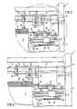
- the device has a stationary stand 1, consisting of four vertical struts 2 and further horizontal cross struts 3 connecting them.
- Spindles which are not visible in the drawing are rotatably mounted in the vertical struts 2 and can simultaneously be driven by a motor (not shown).
- the spindles are connected to one another by gears arranged in the cross struts 3 with end-angle gears.
- a lift 4 is mounted on the spindles, the one rotating Spindles are raised or lowered.
- the lift 4 is provided with supports 5, which are preferably assigned a drivable conveyor belt and which serve to receive a pallet 7 loaded with a paper stack 6.
- the length of the stroke of the lift 4 is equal to the length of the vertical displacement path of the pallet 7.
- the removal of partial stacks 6 serves a removal belt 8 which reaches up to close to the vertical displacement path of the pallet 7.
- the conveyor belt 8 is a telescopic belt. The position of its start can therefore be set close to the stack 6 regardless of the stack format.
- a first carriage 9 is mounted on a horizontal rail 13 so as to be displaceable in the direction of the conveyor belt 8, which carries a stop 10 which can be adjusted vertically between a working and rest position using a linear motor 14.
- This interacts with a sensor 11, which is displaceable along a vertical measuring scale 12.
- the sensor 11, which can also be moved horizontally between a working and rest position, engages over the edge of the pallet protruding from the stack 6 in its working position and is carried along by the pallet 7 along the measuring scale 12 when the elevator 4 is raised. In the rest position, the sensor 11 is outside the vertical displacement path of the pallet 7.
- the stack height H must be determined precisely before the de-stacking begins.
- the sensor 11 is brought into the working position and the lift 4 is raised from its lowest position, until the stack 6 abuts the stop 10, which is also in the working position.
- the sensor 11 is carried along the measuring scale 12 and signals the height H of the stack 6 when the lift comes to a standstill by means of optical or electrical signals.
- the number of partial stacks 6 'to be removed can now be calculated with the height H' and removal can be carried out automatically or manually.
- the stop 10 and the sensor 11 are no longer required for the process of removing the partial stack 6 and moved into their rest position.
- the carriage 9 is driven forward and backward by a motor (not shown) attached to it.
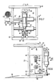
- a bracket 15 Fixed to the carriage 9 is a bracket 15 which carries a separating tongue 16.
- This separating tongue 16 is at the level of the conveyor plane 8 'of the conveyor belt 8 or slightly above.
- the console 15 with its leading flank 23 and the separating tongue 16 form an ejector, which pushes the uppermost partial stack 6 'onto the removal belt 8 when the carriage 9 advances, the separating tongue 16 forming the lower limit of the ejector or partial stack 6' .
- two horizontal guide rods 17 are attached to the stand 1, on which a second carriage 19, which can be driven with a band cylinder 18, is slidably mounted to and fro.
- This second carriage 19 carries two wedge-shaped hold-down devices 20 which are spaced apart from one another and which are seen on the left and right in the direction of movement the separating tongue 16.
- Both hold-down devices 20 can be tilted obliquely downwards from their horizontal or slightly upward position on a horizontal axis 21 on the second carriage 19 with their wedge cutting edge facing the stack 6. Their position is determined by a cylinder piston unit 22.
- the lift 4 is first raised until the stack 6 projects beyond the level of the separating tongue 16 by the height H '.
- the first carriage 9 is moved against the conveyor belt 8 until the separating tongue 16 is in the stack 6 and spreads it between two sheets of paper.
- the separating tongue 16 penetrates so far into the stack 6 until the leading edge 23 of the bracket 15 bears against the part stack 6 'to be separated (FIG. 3).
- the second carriage 19 is moved against the conveyor belt 8 and the hold-down devices 20 are pushed into the gap produced by the separating tongue 16 (FIG. 4). 4, the hold-down device 20 has reached the position shown in FIG. They remain in this tilted position during the subsequent work step and press on the top paper sheet of the remaining stack 6. They exert a restraining force on it.
- the first carriage 9 is moved further against the removal belt 8 until the flank 23 of the ejector 15, 16, 23 reaches the beginning of the removal belt.
- the ejector 15, 16, 23 pushes the partial stack 6 'lying on the separating tongue 16' in front of it onto the discharge belt 8.
- the separating tongue 16 is provided with blown air openings. Through this, blown air is pressed into the wedge-shaped gap during the entire separation process, so that an air cushion forms in the parting plane between the part stack 6 'to be separated and the rest stack, which facilitates the lateral pushing away of the part stack 6'.
- the conveyor belt 8 has a surface with a pronounced friction structure. As soon as during the pushing away of the partial stack 6 to be separated, the preceding lower edge of which strikes the removal belt 8, it is grasped with friction and removed from the remaining stack, thereby supporting the pushing action of the ejector 15, 16, 23.
- the bracket 15 is mounted on the carriage 9 so as to be vertically displaceable by means of a guide 24 and is held in its lower position shown in the drawing by a pneumatic spring 25.
- the stop 10 is brought down by the linear motor 14 into its working position.
- the carriage 9 is moved so far against the conveyor belt 8 that the cutting edge of the separating tongue 16 lies over the projecting edge of the pallet 7.
- the lift 4 is raised until the last partial stack 6 'at the stop 10 and the separating tongue 16 is present at the edge of the pallet.
- the stop 10 is raised to the rest position (dash-dotted) and the lift 4 by a few Raised millimeters further.
- the separating tongue 16 is also lifted and the pneumatic spring 25 is compressed, which thereby presses the separating tongue onto the edge of the pallet.
- the carriage 9 is moved against the conveyor belt 8 and the last partial stack 6 'pushed onto it by means of the ejector 15, 16, 23.
- the force exerted by the pneumatic spring 25 on the separating tongue 16 ensures that the separating tongue 16 slides under the bottom sheet of the last partial stack 6 'or between these and the pallet 7.
- the lift 4 is lowered again and the empty pallet 7 is exchanged for a loaded one, whereupon the workflow described is repeated.
- the separating tongue 16 can be reliably brought over the projecting edge of the pallet, but after ejecting the second-last sub-stack 6', a sensor 42 fastened to a carriage 42 before moving the separating tongue 16 forward 43 brought into contact with the facing side surface of the last partial stack 6 '.
- the carriage 42 can be moved on the rail 13. So that when the ejector 15, 16, 23 is pushed forward, the preceding end of the separating tongue 16 can be stopped exactly above the projecting edge of the pallet, an upward-facing photoelectric transmitter 44 and receiver is attached to the front end of the sensor, which generates a stop signal as soon as the separating tongue 16 cuts its light barrier. Then the carriage 42 with the sensor 43 in the Starting position moved back and the lift 4 raised until the protruding edge of the pallet 7 abuts the separating tongue 16 and lifts it by a few millimeters.
- the console 15 here consists of two parallel, spaced plates 15 ', 15 ⁇ , which are connected at the top by a plate 45 firmly connected to the guide 24 and at the front by a plate 46 forming the flank 23. Between the plates 15 'and 15 ⁇ extend two firmly connected guide rods 49 and 50, on each of which a bearing bush 51, 52 is axially displaceable. A support plate 53 is fixedly connected to the bearing bushes and is displaceable. A support plate 54 is attached to this, on which a pneumatic cylinder 56 hangs pivotably about an axis 55.
- An axis 57 also passes through the support plate 53, to which an angle lever 58 is articulated.
- the other end of the angle lever 58 is pivotally connected to the end of the piston rod of the cylinder 56 by a pivot pin 59.
- the separating tongue 16 is firmly screwed to the angle lever 58.
- the cylinder 53 is pressurized with compressed air in such a way that it holds the separating tongue 16 in a horizontal, unstable, lightweight position.
- Adjusting screws 61 are screwed into two lateral ribs 60 which are firmly connected to the carrier plate 53. These limit a tilting of the preceding end of the separating tongue 16 downward, whereas the stop surface 62 limits an upward tilting of the separating tongue 16.
- a force acts on the free end of the separating tongue from above or below, it can, against dodge the equilibrium force generated by the cylinder 56 up or down until it comes to rest either with the adjusting screws 61 or with the stop 62.
- a force deflecting the separating tongue 16 occurs when the foremost point of the separating tongue 16 hits a sheet of paper and not between two sheets of paper during the advance for unstacking.
- the separating tongue 16 which is held in an unstable equilibrium position, attempts to move up or down, its deflection movement being limited by the upper or lower bow. As a result, it can slide between the hit sheet on the one hand and the adjacent sheet on the other hand, without injuring the hit sheet.
- an electric motor 63 is attached, which drives an eccentric pin 65 via a gear 64, which moves a push rod 66 which extends through a slot opening 67 to and fro.
- the other end of the push rod 66 is articulated on an axle 68 which is fixedly connected to the support plate 53.
- the carrier plate 53 With the engine 118 running, the carrier plate 53 is moved back and forth on the guide rods 49, 50 by the crank mechanism described. It carries out a lateral oscillating movement, the frequency of which can be set via the speed of the motor 63.
- the eccentric radius of the eccentric pin 65 and the length of the push rod 66 are adjustable for adjusting the size of the stroke.
- the console 15, 16, 23 is moved to unstack the stack 6, so that the separating tongue 16 penetrates into the stack 6, the separating tongue 16 is laterally moved back and forth during this advance (at least during the period between the first contact of the separating tongue 16 with the stack 6 and its insertion between two sheets of paper). If (as described) the separating tongue 16 hits a sheet of paper, the lateral oscillating movement favors a deflection of the preceding end against the equilibrium force of the cylinder 56, which promotes the penetration between two sheets and eliminates the risk of injury to the sheet of paper hit.
- the separating tongue 16 In plan view it is in the shape of a scoop and is attached to the bracket 15 or the angle lever 113 with its stem-shaped end. The bottom is essentially flat. In the rear area, the upper side forms a plane 26 parallel to the underside and, starting from the edges 27, 28, has surfaces 31, 32 sloping both towards the sides 29 and towards the preceding edges 30.
- the front part of the separating tongue 16 is tapered in a wedge shape in the direction of movement on the one hand and on the other hand transversely thereto.
- the surfaces of the separating tongue 16 are polished throughout and their leading edges 30 are rounded, the radius of curvature being 0.15 to 0.45 millimeters, preferably 0.3 millimeters.
- the underside of the separating tongue 16 is provided with a groove 33 which is rectangular in cross section and which intersects the surface 32 at the edge 34.
- a sword 35 is inserted into this groove 33, the underside of which is essentially coplanar with the flat underside of the separating tongue 16.
- the sword 35 towers over the leading edges 30 and tapers in the vertical and horizontal directions in a wedge shape.
- the wedge angle ⁇ is 30 ° to 60 °, preferably 45 ° to 55 °.
- the wedge angle is less than 15 °, preferably 5 ° to 10 °.
- the wedge-shaped taper extends up to a line 36 (FIGS. 8 and 9).
- the sword 35 is uniformly thick and rounded in plan view.
- the width of the sword (seen in plan view) is at most 50 millimeters, preferably 30 millimeters.
- the thickness of the flat part 37 of the sword 35 from the line 36 to the sword end is 0.2 to 0.8 millimeters, preferably 0.35 millimeters, these edges also being rounded.
- the visible surfaces of the sword 35 are polished like the other surfaces of the separating tongue 16.
- the preceding edges 30 of the separating tongue 16 are slightly swept backwards.
- the angle enclosed by the edges 30 is 60 ° to 150 ° and is preferably around 120 °.
- the separating tongue 16 is provided with blown air channels 38, which can be connected to the operational compressed air network via the connections 39 and flexible hoses (not shown).
- the blown air channels 38 are connected to numerous blown air openings 40 in the surface of the separating tongue 16.
- the sword 35 is provided with a groove-shaped channel 41 (which can also be omitted), which is connected to the blown air channels 38.
- the channel 41 comes to the surface at the edge 34 and thus opens upwards.
- the blown air channels 38 are each supplied with blown air during the advance of the separating tongue 16, thereby forming an air cushion during their penetration into a stack 6 between the separated layers of paper, which facilitates the lateral pushing away of the partial stack 6 '.
Applications Claiming Priority (4)
| Application Number | Priority Date | Filing Date | Title |
|---|---|---|---|
| CH2905/88 | 1988-08-01 | ||
| CH290588A CH675995A5 (en) | 1988-08-01 | 1988-08-01 | Sheets of paper from stack, removing device |
| CH4603/88 | 1988-12-13 | ||
| CH460388 | 1988-12-13 |
Publications (2)
| Publication Number | Publication Date |
|---|---|
| EP0353527A2 true EP0353527A2 (fr) | 1990-02-07 |
| EP0353527A3 EP0353527A3 (fr) | 1990-09-05 |
Family
ID=25691697
Family Applications (1)
| Application Number | Title | Priority Date | Filing Date |
|---|---|---|---|
| EP19890113030 Withdrawn EP0353527A3 (fr) | 1988-08-01 | 1989-07-15 | Dispositif de désempilage d'une palette chargée d'une pile de feuilles de papier |
Country Status (3)
| Country | Link |
|---|---|
| US (1) | US4955854A (fr) |
| EP (1) | EP0353527A3 (fr) |
| JP (1) | JPH0275540A (fr) |
Cited By (3)
| Publication number | Priority date | Publication date | Assignee | Title |
|---|---|---|---|---|
| EP0529272A1 (fr) * | 1991-07-19 | 1993-03-03 | Fraunhofer-Gesellschaft Zur Förderung Der Angewandten Forschung E.V. | Dispositif pour enlever des articles plats flexibles |
| EP1593627A3 (fr) * | 2004-05-05 | 2007-06-20 | Baumann Maschinenbau Solms GmbH & Co. KG | Dispositif pour automatiquement débiter des piles de matériau en feuilles, en particulier des piles de papier |
| WO2017207510A1 (fr) * | 2016-05-30 | 2017-12-07 | Schur Packaging Systems Ab | Extracteur de feuilles d'une pile |
Families Citing this family (21)
| Publication number | Priority date | Publication date | Assignee | Title |
|---|---|---|---|---|
| CH683089A5 (de) * | 1991-06-19 | 1994-01-14 | Oscar Roth | Bauteilsatz zur Herstellung einer Verpackung. |
| SE505882C2 (sv) * | 1994-02-10 | 1997-10-20 | Alf Peter Nissen | Förfarande och anordning för uppdelning av en stapel av ark i ris och inmatning av risen i en risbindningsanordning |
| US5688463A (en) * | 1995-06-12 | 1997-11-18 | Combibloc, Inc. | Laser processing of discrete sheets of material |
| US5849134A (en) * | 1995-10-11 | 1998-12-15 | Combibloc, Inc. | Processing discrete sheets of material |
| EP0768261A1 (fr) * | 1995-10-12 | 1997-04-16 | Solipat Ag | Dispositif et méthode pour plier et empiler en continu des produits en bande |
| JP2817682B2 (ja) * | 1995-10-13 | 1998-10-30 | 王子製紙株式会社 | 段ボールシート等の供給方法 |
| ITBO20000621A1 (it) * | 2000-10-26 | 2002-04-26 | Innopack S R L | Metodo e dispositivo per il prelievo di risme di fogli |
| EP1264792B1 (fr) * | 2001-06-08 | 2006-08-09 | bielomatik Leuze GmbH + Co KG | Dispositif et procédé de division d'une pile de feuilles en rames d'un nombre de feuilles prédéterminé |
| DE10223350A1 (de) * | 2002-05-25 | 2003-12-04 | Kolbus Gmbh & Co Kg | Vorrichtung zum Vereinzeln und Zuführen des jeweils untersten Bogens aus einem Stapel |
| ITBO20030248A1 (it) * | 2003-04-29 | 2004-10-30 | Gd Spa | Metodo e dispositivo per il prelievo di pile di sbozzati. |
| ITBO20030489A1 (it) * | 2003-08-08 | 2005-02-09 | Kpl Packaging Spa | Metodo per la formazione e il prelievo di risme di fogli |
| ITBO20060238A1 (it) * | 2006-04-04 | 2007-10-05 | Giben Int Spa | Apparato per formare pacchi di pannelli e per alimentarli verso una stazione utilizzatrice. |
| JP5309467B2 (ja) * | 2007-04-25 | 2013-10-09 | 村田機械株式会社 | 板材加工システム |
| US8671596B2 (en) * | 2007-07-25 | 2014-03-18 | Patrick R. Manion | Ultrasonic ice shaving blade |
| US7991307B2 (en) * | 2007-09-24 | 2011-08-02 | Xerox Corporation | Media elevator's current position identification method and a media handling device arranged with the same |
| DK201670378A1 (en) * | 2016-05-30 | 2017-12-11 | Schur Packaging Systems Ab | Pile Preparation Unit with Pallet Exchange Module |
| KR101879630B1 (ko) * | 2016-08-22 | 2018-07-18 | 박재홍 | 지류의 손상을 방지할 수 있는 지류 분리장치 |
| KR20180021400A (ko) * | 2016-08-22 | 2018-03-05 | 박재홍 | 위치 측정부가 구비된 지류 분리장치 |
| WO2020039422A1 (fr) | 2018-08-20 | 2020-02-27 | Kornit Digital Ltd. | Mécanisme de chargement pour chemises |
| ES2965621T3 (es) * | 2019-08-12 | 2024-04-16 | L&P Swiss Holding Gmbh | Máquina para desapilar objetos |
| CN114030932A (zh) * | 2022-01-07 | 2022-02-11 | 广东台一精工机械有限公司 | 一种瓦楞纸板分垛送料装置 |
Citations (9)
| Publication number | Priority date | Publication date | Assignee | Title |
|---|---|---|---|---|
| GB165323A (en) * | 1920-06-11 | 1921-06-30 | Dexter Folder Co | Improvements in sheet separating machines |
| FR973010A (fr) * | 1948-04-14 | 1951-02-06 | Burn & Co Ltd James | Machine à poinçonner automatiquement le papier |
| US3206042A (en) * | 1963-04-17 | 1965-09-14 | Peterson Eric Ronald | Multiple sheet handling device |
| DE1804374A1 (de) * | 1968-02-14 | 1969-09-04 | Buero Walter Kugler Ing | Vorrichtung zur abschnittsweisen Abtragung eines Stapels von blattfoermigen Gegenstaenden,beispielsweise Papierblaetter |
| GB2092116A (en) * | 1981-02-03 | 1982-08-11 | Bobst Sa | Device for introducing sheet batches into a processing machine |
| JPS58144032A (ja) * | 1982-02-19 | 1983-08-27 | Sumitomo Rubber Ind Ltd | 紙葉類搬送用エンドレスゴムベルト |
| US4620827A (en) * | 1983-12-26 | 1986-11-04 | Honshu Seishi Kabushiki Kaisha | Apparatus for supplying flat sheets such as pulp sheets |
| DE3641434A1 (de) * | 1986-12-04 | 1988-06-09 | Bielomatik Leuze & Co | Vereinzelungs-vorrichtung fuer mehrfach-lagenstapel aus blattlagen |
| DE3740355A1 (de) * | 1986-12-16 | 1988-06-23 | Wrapmatic Spa | Vorrichtung zum automatischen abtrennen von grossformatigen losen ries, ausgehend von einem packen gestapelter boegen, und deren zufuehrung an verpackungsmaschinen sowie das entsprechende verfahren |
Family Cites Families (4)
| Publication number | Priority date | Publication date | Assignee | Title |
|---|---|---|---|---|
| DE3502176A1 (de) * | 1985-01-23 | 1986-07-24 | Bielomatik Leuze Gmbh + Co, 7442 Neuffen | Vorrichtung zum falzen von materialbahnen |
| US4721295A (en) * | 1986-08-12 | 1988-01-26 | Kimberly-Clark Corporation | Apparatus and process for separating stacks of sheets into bundles |
| DE3635895A1 (de) * | 1986-10-22 | 1988-05-05 | Will E C H Gmbh & Co | Verfahren und vorrichtung zum trennen einer zick-zack-foermig gefalteten materialbahn |
| DE3870978D1 (de) * | 1987-04-16 | 1992-06-17 | Involvo Ag | Vorrichtung zum unterteilen einer endlosen papierbahn mit zickzackfalzung. |
-
1989
- 1989-07-15 EP EP19890113030 patent/EP0353527A3/fr not_active Withdrawn
- 1989-07-28 US US07/387,163 patent/US4955854A/en not_active Expired - Fee Related
- 1989-08-01 JP JP1200130A patent/JPH0275540A/ja active Pending
Patent Citations (9)
| Publication number | Priority date | Publication date | Assignee | Title |
|---|---|---|---|---|
| GB165323A (en) * | 1920-06-11 | 1921-06-30 | Dexter Folder Co | Improvements in sheet separating machines |
| FR973010A (fr) * | 1948-04-14 | 1951-02-06 | Burn & Co Ltd James | Machine à poinçonner automatiquement le papier |
| US3206042A (en) * | 1963-04-17 | 1965-09-14 | Peterson Eric Ronald | Multiple sheet handling device |
| DE1804374A1 (de) * | 1968-02-14 | 1969-09-04 | Buero Walter Kugler Ing | Vorrichtung zur abschnittsweisen Abtragung eines Stapels von blattfoermigen Gegenstaenden,beispielsweise Papierblaetter |
| GB2092116A (en) * | 1981-02-03 | 1982-08-11 | Bobst Sa | Device for introducing sheet batches into a processing machine |
| JPS58144032A (ja) * | 1982-02-19 | 1983-08-27 | Sumitomo Rubber Ind Ltd | 紙葉類搬送用エンドレスゴムベルト |
| US4620827A (en) * | 1983-12-26 | 1986-11-04 | Honshu Seishi Kabushiki Kaisha | Apparatus for supplying flat sheets such as pulp sheets |
| DE3641434A1 (de) * | 1986-12-04 | 1988-06-09 | Bielomatik Leuze & Co | Vereinzelungs-vorrichtung fuer mehrfach-lagenstapel aus blattlagen |
| DE3740355A1 (de) * | 1986-12-16 | 1988-06-23 | Wrapmatic Spa | Vorrichtung zum automatischen abtrennen von grossformatigen losen ries, ausgehend von einem packen gestapelter boegen, und deren zufuehrung an verpackungsmaschinen sowie das entsprechende verfahren |
Non-Patent Citations (1)
| Title |
|---|
| PATENT ABSTRACTS OF JAPAN vol. 7, no. 265 (M-258)(1410) 25 Oktober 1983, & JP-A-58 144032 (SUMITOMO GOMU KOGYO K.K.) 27 August 1983, * |
Cited By (4)
| Publication number | Priority date | Publication date | Assignee | Title |
|---|---|---|---|---|
| EP0529272A1 (fr) * | 1991-07-19 | 1993-03-03 | Fraunhofer-Gesellschaft Zur Förderung Der Angewandten Forschung E.V. | Dispositif pour enlever des articles plats flexibles |
| EP1593627A3 (fr) * | 2004-05-05 | 2007-06-20 | Baumann Maschinenbau Solms GmbH & Co. KG | Dispositif pour automatiquement débiter des piles de matériau en feuilles, en particulier des piles de papier |
| WO2017207510A1 (fr) * | 2016-05-30 | 2017-12-07 | Schur Packaging Systems Ab | Extracteur de feuilles d'une pile |
| CN110049935A (zh) * | 2016-05-30 | 2019-07-23 | 舒尔技术股份公司 | 堆叠件片材移除器 |
Also Published As
| Publication number | Publication date |
|---|---|
| US4955854A (en) | 1990-09-11 |
| EP0353527A3 (fr) | 1990-09-05 |
| JPH0275540A (ja) | 1990-03-15 |
Similar Documents
| Publication | Publication Date | Title |
|---|---|---|
| EP0353527A2 (fr) | Dispositif de désempilage d'une palette chargée d'une pile de feuilles de papier | |
| DE3613316C1 (de) | Vorrichtung zum Schneiden von gestapeltem,blattfoermigem Gut | |
| DE3922803B4 (de) | Selbsttätig arbeitende Blattstapel-Ladevorrichtung für eine Blatt-Zuführvorrichtung | |
| EP0056874B1 (fr) | Machine pour couper le papier etc. | |
| DE2443106C2 (de) | Stapelvorrichtung zur Bildung eines Stapels gegeneinander versetzt angeordneter Blattstöße | |
| EP0432225B1 (fr) | Dispositif de decoupage de feuilles empilees | |
| DE2913439C2 (fr) | ||
| DE2639676C2 (de) | Vorrichtung zum Beschicken eines Rundstapelbogenanlegers | |
| EP0433755B1 (fr) | Dispositif pour l'empilement vertical automatique de feuilles | |
| DE3414996C1 (de) | Vorrichtung zum Abschieben von auf einer Trageinrichtung abgelegten Stapeln oder Paketen | |
| DE2508745C2 (de) | Vorrichtung zum Aufstauen vereinzelt mittels einer Transportvorrichtung zugeförderter Papierbögen zu Stapeln und zum Weitertransportieren dieser Stapel | |
| EP1873095B1 (fr) | Dispositif de séparation, en particulier d'enlèvement d'une partie de la pile dotée d'au moins une plaque de grand format d'une pile résiduelle dotée de plusieurs plaques de grand format | |
| DE3107437C2 (fr) | ||
| CH680363A5 (fr) | ||
| EP0243944B1 (fr) | Dispositif pour fabriquer des paquets ou des piles de feuilles de papier pliées | |
| DE19804667C1 (de) | Verfahren zum Justieren eines Messers beim Messerwechsel sowie Schneidmaschine mit Messerwechselvorrichtung | |
| DE3219693A1 (de) | Vorrichtung zur bildung von verarbeitungsfaehigen teilstapeln aus folienbogen, insbesondere papierbogen | |
| EP1184161B1 (fr) | Appareil pour dresser des boítes à des ébauches de carton | |
| DE2544139A1 (de) | Vorrichtung zum trennen und stapeln mehrerer aus einem kartonbogen o.dgl. gestanzter kartonzuschnitte | |
| DE4008592A1 (de) | Vorrichtung zum automatischen Zu- und Abführen von Platten aus Karton, Wellpappe und dergl., zu einer Stanz- und/oder Druckmaschine | |
| DE2744061A1 (de) | Vorrichtung fuer die automatische aufstapelung von streifen, welche aus der maschine fuer die herstellung derselben auslaufen | |
| DE4244089A1 (de) | Verfahren und Vorrichtung zur automatischen Stapelung von konkaven Gegenständen wie Schalen, Teller, Becher o. dgl. aus Kunststoff oder Papier | |
| CH675995A5 (en) | Sheets of paper from stack, removing device | |
| DE2429903A1 (de) | Vorrichtung zum loesen von ausgestanztem stanzgut aus einem stapel bzw. zum abtrennen von stanzgut und abfall | |
| EP1264794B1 (fr) | Méthode et dispositif pour la formation d'une pile sur un récepteur de pile |
Legal Events
| Date | Code | Title | Description |
|---|---|---|---|
| PUAI | Public reference made under article 153(3) epc to a published international application that has entered the european phase |
Free format text: ORIGINAL CODE: 0009012 |
|
| AK | Designated contracting states |
Kind code of ref document: A2 Designated state(s): AT BE CH DE ES FR GB GR IT LI LU NL SE |
|
| PUAL | Search report despatched |
Free format text: ORIGINAL CODE: 0009013 |
|
| AK | Designated contracting states |
Kind code of ref document: A3 Designated state(s): AT BE CH DE ES FR GB GR IT LI LU NL SE |
|
| 17P | Request for examination filed |
Effective date: 19910301 |
|
| 17Q | First examination report despatched |
Effective date: 19921106 |
|
| STAA | Information on the status of an ep patent application or granted ep patent |
Free format text: STATUS: THE APPLICATION IS DEEMED TO BE WITHDRAWN |
|
| 18D | Application deemed to be withdrawn |
Effective date: 19930318 |