EP0243944B1 - Dispositif pour fabriquer des paquets ou des piles de feuilles de papier pliées - Google Patents
Dispositif pour fabriquer des paquets ou des piles de feuilles de papier pliées Download PDFInfo
- Publication number
- EP0243944B1 EP0243944B1 EP87106194A EP87106194A EP0243944B1 EP 0243944 B1 EP0243944 B1 EP 0243944B1 EP 87106194 A EP87106194 A EP 87106194A EP 87106194 A EP87106194 A EP 87106194A EP 0243944 B1 EP0243944 B1 EP 0243944B1
- Authority
- EP
- European Patent Office
- Prior art keywords
- stack
- sheets
- magazine
- guides
- sheet
- Prior art date
- Legal status (The legal status is an assumption and is not a legal conclusion. Google has not performed a legal analysis and makes no representation as to the accuracy of the status listed.)
- Expired - Lifetime
Links
Images

Classifications
-
- B—PERFORMING OPERATIONS; TRANSPORTING
- B65—CONVEYING; PACKING; STORING; HANDLING THIN OR FILAMENTARY MATERIAL
- B65H—HANDLING THIN OR FILAMENTARY MATERIAL, e.g. SHEETS, WEBS, CABLES
- B65H31/00—Pile receivers
- B65H31/04—Pile receivers with movable end support arranged to recede as pile accumulates
- B65H31/08—Pile receivers with movable end support arranged to recede as pile accumulates the articles being piled one above another
- B65H31/10—Pile receivers with movable end support arranged to recede as pile accumulates the articles being piled one above another and applied at the top of the pile
-
- B—PERFORMING OPERATIONS; TRANSPORTING
- B65—CONVEYING; PACKING; STORING; HANDLING THIN OR FILAMENTARY MATERIAL
- B65B—MACHINES, APPARATUS OR DEVICES FOR, OR METHODS OF, PACKAGING ARTICLES OR MATERIALS; UNPACKING
- B65B27/00—Bundling particular articles presenting special problems using string, wire, or narrow tape or band; Baling fibrous material, e.g. peat, not otherwise provided for
- B65B27/08—Bundling paper sheets, envelopes, bags, newspapers, or other thin flat articles
-
- B—PERFORMING OPERATIONS; TRANSPORTING
- B65—CONVEYING; PACKING; STORING; HANDLING THIN OR FILAMENTARY MATERIAL
- B65H—HANDLING THIN OR FILAMENTARY MATERIAL, e.g. SHEETS, WEBS, CABLES
- B65H33/00—Forming counted batches in delivery pile or stream of articles
- B65H33/12—Forming counted batches in delivery pile or stream of articles by creating gaps in the stream
-
- B—PERFORMING OPERATIONS; TRANSPORTING
- B65—CONVEYING; PACKING; STORING; HANDLING THIN OR FILAMENTARY MATERIAL
- B65H—HANDLING THIN OR FILAMENTARY MATERIAL, e.g. SHEETS, WEBS, CABLES
- B65H2301/00—Handling processes for sheets or webs
- B65H2301/40—Type of handling process
- B65H2301/42—Piling, depiling, handling piles
- B65H2301/422—Handling piles, sets or stacks of articles
- B65H2301/4223—Pressing piles
-
- B—PERFORMING OPERATIONS; TRANSPORTING
- B65—CONVEYING; PACKING; STORING; HANDLING THIN OR FILAMENTARY MATERIAL
- B65H—HANDLING THIN OR FILAMENTARY MATERIAL, e.g. SHEETS, WEBS, CABLES
- B65H2301/00—Handling processes for sheets or webs
- B65H2301/40—Type of handling process
- B65H2301/43—Gathering; Associating; Assembling
- B65H2301/438—Finishing
- B65H2301/4382—Binding or attaching processes
- B65H2301/43824—Binding or attaching processes involving wrapping, banding or strapping
-
- B—PERFORMING OPERATIONS; TRANSPORTING
- B65—CONVEYING; PACKING; STORING; HANDLING THIN OR FILAMENTARY MATERIAL
- B65H—HANDLING THIN OR FILAMENTARY MATERIAL, e.g. SHEETS, WEBS, CABLES
- B65H2402/00—Constructional details of the handling apparatus
- B65H2402/30—Supports; Subassemblies; Mountings thereof
- B65H2402/35—Supports; Subassemblies; Mountings thereof rotating around an axis
- B65H2402/352—Turrets
Definitions
- the invention relates to a device for producing bundled bars from folded paper sheets, in particular from folded printed sheets, with a sheet feed station, the conveying means for feeding the sheets in the form of a shingled stream, a retaining device for intermittent interruption of the shingled stream and optionally means for counting and aligning the fed Sheet has, at least one stacking magazine with a height-adjustable bottom, a station for the introduction of protective plates in the form of bottom and cover plates into the stacking magazine and with a station for pressing and strapping the rod formed in the stacking magazine.
- the printed sheets coming from a rotary machine for example a printing or folding machine
- a rotary machine for example a printing or folding machine
- the manual stacking of individual packages on pallets requires a great deal of care and experience, otherwise the handy individual packages will fall apart.
- this process no longer meets today's occupational physiological and ergonomic requirements. Because the operator cannot interrupt the work as long as the sheet delivery of the rotary machine is running and has to move considerable masses by hand, for example 1200 kg / h with a single sheet weight of approx. 60 g. In addition, loose stacking takes up a lot of space.
- a stacking device which mechanically forms rods from 200 to 300 sheets from the stream of shingles, which are then pressed and tied with a belt or automatically strapped and stacked on pallets and in this form until further processing e.g. are temporarily stored in bookbinders.
- this device reduces the physical effort of the operating personnel and the space requirement, but does not solve the problem of the inclination of the stack due to the different sheet height in the area of the fold on the one hand and the unfolded edges on the other.
- a device of the type mentioned in which the sheets are also fed to the stream of flakes and are thrown into a magazine into a vertical bar, moving downward on a support forming the bottom of the magazine, the discarded stack is then pressed together in the magazine, after placing a protective plate on the last sheet, and is strapped with a band by means of a special strapping device.
- a retaining device is provided which retains the shingled stream during the pressing process, so that at the same time the insertion of a new support plate onto an auxiliary stacking level can be carried out, on which the next sheets can already be stacked until the main stack carrier, after removal of the previously strapped stack again takes over the newly forming stack.
- a complex second pressing device is proposed to solve the above-described problem of different sheet heights, which presses the uppermost printed sheets of the started bar on the fold side during stack formation and up to the longitudinal axis
- the pressing of the rod which has been completely ejected up to the desired height, continuously holds in the pressed state.
- the second pressing device required for this is expensive because, depending on the machine cycle, they intervene in the magazine space during the ejection of the sheets, compress the sheets in the area of the fold, when the stack being formed is taken over from the auxiliary stack level to the
- the main stack carrier must be moved out of the magazine room and then returned to the original position. All these movements of the second pressing device disturb the very sensitive process of stack formation, without the actual problem being solved satisfactorily. Because the sheets are compressed on their higher side due to the inclusion of air, but the air between the layers of paper can only imperfectly escape at the open edges of the sheets, because with increasing stack height the weight of the sheets prevents the enclosed air from escaping completely. This creates uneven air cushions within and between the individual sheets. This in turn can damage the paper surface, causing it to wrinkle.
- the invention has for its object to provide a solution to the problem associated with the different height of folded printed sheets while avoiding the disadvantages of the known devices, ie to create a device with which it is also possible to form higher stacks in which the individual sheets lie flat with little equipment.
- the device to be created should be universally applicable, that is, it should also be usable for stacking unfolded sheets, and in addition, the physical effort of the operating personnel in the sense of humanizing the ar be reduced without reducing productivity.
- the stacking magazine is arranged on a movable or movable table which, however, can be locked in predetermined positions and has side guides which define the stacking space of the magazine and in that the front side guides closest to the edges of the table Wear brush strips over at least the lower part of their vertical extension, the bristles of which protrude into the stacking magazine in such a way that they at least partially engage in the stacked sheets and their leaves in the region of the unfolded edges.
- the arrangement of the at least one stacking magazine on a movable or movable table, which can be locked in predetermined positions, creates the possibility of providing several stacking magazines which, when the desired stacking height is reached, move from the discharge position aligned with the sheet feeding station into one or more further positions can be either press and strapping stations or rest stations.
- a second or a further magazine can already be filled to form a new stack while the first stack is still being pressed and strapped or is waiting in a rest position until it is removed by the operating personnel. This results in breaks for the operating personnel, which do not have a negative impact on the productivity of the system.
- the special design of the side guides defining the stacking space of the magazine with integrated brush strips ensures that the different heights of folded sheets in the area of the fold on the one hand and in the area of the unfolded open edges on the other hand is compensated for in the simplest way because the bristles are in the stacked sheets and whose sheets engage in the area of the unfolded edges.
- the engagement of the bristles between the leaves not only has the effect of compensating for the different heights at the edges of the sheets, but at the same time has the effect that in the area of the open edges the sheet openings remain free for the escape of enclosed air cushions if and for as long as the discarded stack by means of a pressing device is pressed together.
- the brush strips used according to the invention are also very easily adjustable and adaptable to all paper qualities and sheet formats.
- the brush strips can be replaced easily overall, harder or softer bristles can be used, bristles of different diameters made of different filaments and different lengths can be used, the bristles can have the same or a continuously or discontinuously changing penetration depth over the entire height of the stacking magazine , so that the device can be individually adapted to any application.
- the movable or movable table can have any shape and can either be linearly movable or rotatable about a fixed axis. Particularly preferred is the design as a rotary table, which is rotatably mounted about a vertical axis, so that several stacking magazines can be arranged on the table, and particularly advantageously three to eight such magazines. In this way, the main assemblies of the device, i.e.
- the sheet feed station and the station for pressing and strapping in predetermined positions, corresponding to the ascertainable positions of the movable or movable table, around the table in a space-saving, easily accessible from all sides, ergonomically favorable manner arrange so that each magazine can move from one station to the next in a very short time by moving or rotating the table, while the separating device temporarily interrupts the shingled stream, but the delivery of the rotating machine supplying the shingled stream does not need to be stopped.
- the other positions of the movable or movable table which are free of units such as sheet feed station or pressing and strapping station, are rest positions in which the bundled, optionally pressed and strapped rods are available for manual or mechanical removal by the operating personnel. If six or eight magazines are arranged on a rotary table, the operating personnel can, for example, wait until four or six magazines are filled in order to then remove the finished bundled bars at once. This reduces physical effort and the breaks are longer.
- an ejection device with an associated transport route, e.g. a roller or roller table.
- Advantageous embodiments of the device according to the invention are further characterized in that the side guides of the stacking magazines are releasably attached to the table and adjustable to the respective sheet format, and that the brush strips are releasably attached to the side guides and adjustable in terms of the depth of their engagement in the stacked sheets and their sheets are trained. This achieves the format variability required for the universal usability of the device and the adaptability of the device to different paper qualities and different types of folds
- an angle guide is attached to the front side guides in a further advantageous embodiment of the invention, which encloses the front corners of the stacked sheets for protection against damage, but also for stacking one on top of the other in register, these angular guides preferably being designed such that they can be swung open or pivoted, so that the front legs the angle guides are not in the way when removing the bars.
- An embodiment is particularly advantageous in which the angle guides on the side guides by means of suitable guide means, e.g. Wedge surfaces and obliquely upwardly extending grooves with bolts engaging in the grooves are designed to be displaceable such that the front corners of the stacked sheets are freely accessible for removing the bundled rods.
- suitable guide means e.g. Wedge surfaces and obliquely upwardly extending grooves with bolts engaging in the grooves
- the angle guides can be moved forward or to the side or swiveled at the same time, so that they are in no way a hindrance to the removal of the bundled rods.
- angle guides are provided with plungers which carry rollers at their lower ends in order to be able to roll on the floor or on a supporting plate when the table is moving. If the plungers now interact with overrun cams, they are pushed upwards in predetermined positions when the table is moving or displaced, when they run up onto the cams and thereby move the angle guides in the manner described above, so that the bundled rods are unhindered from the magazines can be removed.
- a holding rake for non-pressed and non-strapped counted sheet sections is attached to the side guides of the stacking magazines in a height-adjustable manner.
- counted sheet sections of, for example, 20 or 30 individual sheets can be stacked and removed in cycles from a selectable working height that can be set by the operating personnel.
- the device according to the invention can preferably be driven on its rollers with all of its units.
- the sheet feed station can have a height-adjustable feed table, so that the device according to the invention can be adjusted to any delivery of a folding machine, printing machine or other rotary machine for taking over the sheets.
- a strip marking device is advantageous for shooting marking strips between counted batches of sheets stacked.
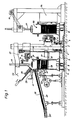
- the embodiment of the device according to the invention for producing bundled bars from paper sheets shown in FIG. 1 has a machine frame plate 1 with which the vertical axis 2 as the fulcrum axis for the rotatable rotary table 3 is firmly connected.
- a flange bearing 4, which is fixedly connected to the rotary table 3, which has ball bearings on the axis 2, can be rotated by means of the drive motor 6 via the drive belt 7 and the drive wheel 5, the motor 6 being controlled by means of electronic switching means (not shown) in such a way that that the table can be locked in predetermined positions.
- the drive motor 6 is attached to the axis 2.
- Support rollers 8 are attached to the underside of the rotary table 3, which are supported on the machine frame plate 1 and roll on the machine frame plate when the table rotates.
- Each stacking magazine 40 is arranged on the rotary table 3 at equal angular intervals (FIG. 2).
- the stacking space of each magazine 40 is defined by side guides 9, 9 ', 10.
- the side guides of the stacking magazines 40 are detachably fastened on the table 3 and adjustable to the respective sheet format.
- the front side guides 10 consist of a basic guide 11 (FIG. 4) which is adjustably attached to the rotary table 3, and of angular guides 12 which prevent the sheets 31 stacked in the magazine 40 from falling out by enclosing the front corners of the stacked sheets 31 .
- the angle guides 12 are laterally displaceable, foldable and / or pivotable on the basic guides 11 of the side guides 10 in order to make the bundled bars of paper sheets 31 stacked in the magazines 40 freely accessible and to enable them to be taken out of the magazines without hindrance.
- Brush strips 13 are also releasably attached to the side guides 10.
- the vertically attached brush strip 13 can be adjusted to the type and format of the stacked sheets 31 by means of elongated hole fastening and clamping screw 32, so that the bristles 44 differ in the stack space of the respective magazine 40 can protrude.
- the brush strips 13 are thus adjustable in terms of the depth of their engagement in the stacked sheets 31 and their leaves.
- the brush strips 13 can be inclined by means of the elongated hole fastening and the clamping screw 32, so that the bristles engage more in the upper region of the magazine 40 than below, or they can be found in an exactly vertical position (FIG. 6), so that the bristles 44 extend the same length into the stacking space of the magazine 40 over the entire length of the brush strips 13.
- brush strips 13 can be used which are equipped with bristles 44 of different lengths or the bristles of different diameters. or wear bristles made of different rigid materials.
- a wedge-shaped sliding surface 14 with an upwardly sloping groove 15 is arranged at the top and bottom of the angle guides 12.
- a guide pin 16 is connected to the basic guide 11 and serves as a guide and stop for the groove 15.
- the basic guides 11 also have wedge-shaped surfaces 14 'at the points at which the wedge-shaped sliding surfaces 14 abut, so that the angular guides 12, when pressed or pulled up, move not only to the side but also to the front.
- the surface guide by means of the wedge-shaped surfaces 14, 14 'and the guide means 15, 16 thus ensures that the angle guides 12 are pivoted away to the side, so that the bundled rods from the magazines 40 can be carried comfortably without hindrance and without risk of damage to the corners or edges of the individual sheets 31 can be removed manually or ejected mechanically.
- the displacement of the angle guides 12 on the sliding surfaces 14, 14 ' can be accomplished either by means of a handle, not shown, or automatically by a plunger 17 with roller 18 which is guided through the rotary table 3 (FIG. 6), so that the roller 18 is on the machine frame plate 1 can roll when the table 3 is rotated about the axis 2.
- cams 19 are attached in predetermined positions, onto which the tappets 17 run with their rollers 18 as soon as the corresponding magazine 40 reaches the removal positions 111 to VI (FIG. 2) by rotating the table 3 about the axis 2.
- the rollers 18 and the cams 19 With the help of the plunger 17, the rollers 18 and the cams 19, the magazines 40 in positions 111 to VI are automatically opened by laterally pivoting the angle guides 12, but closed again with each rotation of the table 3 and only when one of the positions III is reached to VI opened again.
- retaining flaps 30 are resiliently attached.
- the retention flaps 30 hold back the sheets 31 thrown from the sheet feed station 20 through the rollers 23 into the magazine 40, so that the sheets can only migrate into the magazine in one direction, but cannot move back.
- the brush strips 13 mounted vertically on the side guides 10 end below the resilient retaining flaps 30. When the magazine is open (FIG. 5), the brush strips 13 prevent the rod stacked in the magazine from falling out unintentionally.
- the main purpose of the brush strips 13 is, however, to fan out the sheets 31 stacked in the magazine 40, so that their different heights in the area of the fold on the one hand and the open edges on the other hand are compensated for and at the same time it is ensured that the air enclosed within and between the sheets when Squeezing the stack can escape safely. That is why the sheets are not crooked, even with larger stack heights, but horizontal and flat, do not bulge and form a flat surface on the top for the subsequent sheets.
- the drive motor 25 with drive spindle 26 for the stack carrier housing 27, which contains a drive for the stack carrier 28, is fixedly attached to the axis 2.
- the stack carriers are mounted in ball bushings, the stack carriers 28 preferably being designed as toothed racks and equipped with toothed drive means (not shown).
- the stack carriers 28 are moved into the stack magazine 40 between the stack guides 9 by means of the drive means mentioned and form a carrier for the stack.
- a base plate 38 which forms the stacking base, is first dropped into the empty magazine 40 in cycles. After the desired stack height has been reached, a further plate 38 is thrown off the protective plate feed station 22 as a cover plate onto the uppermost sheet 31 located in magazine 40.
- a depressing die 29 with an eccentric drive 24 and drive motor 33 is fixed in place on the axis 2 above the stacking magazine 40 in position I.
- a strapping station 34 known per se which is additionally equipped with a press ram 35 and a drive 36, is located in position 11 in the exemplary embodiment shown.
- a retaining device 21 for intermittently interrupting the shingled stream 37 with the formation of individual columns or partial sheds as well as optionally means for counting and aligning the fed sheets is attached.
- the sheet feed station 20 is adjustable in height so that on the one hand the inclination of the shingled stream 37 can be changed and on the other hand a height adjustment to the delivery 20 'of any rotary, printing or folding machine is possible.
- a strip marking device 45 (FIG. 1) for shooting marking strips 46 between the counted portions of the sheets 31 stacked in the magazine 40 is located below the sheet feed station 20.
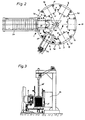
- a stationary or rotatable ejection device 41 is located behind the magazines 40 in at least one of the positions 111 to VI, with which the bundled and optionally strapped rods can be ejected from the magazine 40 onto a transport path 42 (FIG. 7) .
- a holding rake 43 (FIG. 8) can be arranged on the side guides 9 'so as to be height-adjustable.
- the device according to the invention works as follows:
- the shingled stream 37 of folded or unfolded sheets is conveyed to the rollers or rollers 23 with the aid of conveyor belts or belts and from there, with the sheet folded with the fold ahead, is thrown into the stack magazine 40.
- the shingled stream 37 can be interrupted without the conveyor belts having to be stopped.
- the stack carrier 28 was moved into its uppermost position by means of the spindle drive 25, 26 and into the stacking space of the magazine 40 by means of the rack and pinion drive housed in the stack carrier housing 27. As long as the shingled stream 37 was still interrupted by means of the retaining device 21, a protective plate 38 was dropped from the protective plate feed station 22 onto the stack carrier 28 as a base plate.
- the first sheet 31 of each column is thrown onto the base plate 38, all subsequent sheets onto the preceding sheet.
- the light barrier 39 which is part of an opto-electronic counting, control and switching device, not shown, the desired stack height is controlled and monitored.
- the shingled stream 37 is interrupted again by means of the retaining device 21 and, at the same time, another protective plate 38 is thrown out of the protective plate feed station 22 as a cover plate onto the stack formed in the magazine.
- the stack carrier 28 moves downward in synchronism with the increase in the stack height in the magazine 40 with the aid of the spindle drive 25, 26.
- the depressing stamp 29 performs a stroke downwards at intervals and presses the cover plate or the uppermost arch of the last thrown column under the retaining flaps 30 and between them Brush strips 13, which are attached to the side guides 10 (intermediate pressure).
- the retaining device 21 releases the sheet flow again and the next column can be thrown into the magazine 40. This process is repeated periodically, each time after a predeterminable number of sheets, until the magazine is filled or the desired stack height is reached.
- the scale flow 37 is stopped.
- the stack carrier 28 is then moved back out of the magazine 40, the base plate 38 with the stack resting thereon resting on supports of the side guides 9, 9 ', 10. If the uppermost sheet 31 of the discarded stack does not yet have a protective plate 38 as the cover plate, this is now discarded and pressed under the retaining flaps 30 with the depressing stamp 29.
- the rotary table 3 is then rotated by 60 ° in the direction of the arrow (FIG. 2), as a result of which the filled magazine 40 moves up from the original position I into the position 11 and at the same time an empty magazine moves up from position VI into position I.
- the stacked sheets of the full stack magazine 40 in position II are pressed into a bar and strapped. This process is completed before a new cycle movement of the rotary table 3.
- the next cycle movement brings the magazine with the bundled, pressed and strapped rod into the position 111 or into the positions 111 to VI available as rest positions for the removal of the rods, from where the rods either manually or mechanically using the ejection device 41 can be removed.
- the angle guides 12 of the front side guides 10 are opened in the positions 111 to VI, so that the rods can be removed; however, they close automatically during each cycle movement of the rotary table 3, so that the bundled rods, as long as they are not removed, cannot fall out unintentionally.
Landscapes
- Engineering & Computer Science (AREA)
- Mechanical Engineering (AREA)
- Basic Packing Technique (AREA)
Claims (14)
Applications Claiming Priority (2)
| Application Number | Priority Date | Filing Date | Title |
|---|---|---|---|
| DE8611717U | 1986-04-29 | ||
| DE8611717U DE8611717U1 (de) | 1986-04-29 | 1986-04-29 | Bogenstapelvorrichtung zur Herstellung einer gebündelten Stange aus Papierbogen |
Publications (2)
| Publication Number | Publication Date |
|---|---|
| EP0243944A1 EP0243944A1 (fr) | 1987-11-04 |
| EP0243944B1 true EP0243944B1 (fr) | 1990-07-04 |
Family
ID=6794164
Family Applications (1)
| Application Number | Title | Priority Date | Filing Date |
|---|---|---|---|
| EP87106194A Expired - Lifetime EP0243944B1 (fr) | 1986-04-29 | 1987-04-29 | Dispositif pour fabriquer des paquets ou des piles de feuilles de papier pliées |
Country Status (2)
| Country | Link |
|---|---|
| EP (1) | EP0243944B1 (fr) |
| DE (2) | DE8611717U1 (fr) |
Families Citing this family (13)
| Publication number | Priority date | Publication date | Assignee | Title |
|---|---|---|---|---|
| DE3705169A1 (de) * | 1987-02-18 | 1988-09-01 | Sesto Palamides | Verfahren und vorrichtung zum verpacken von druckerzeugnissen |
| IT1223446B (it) * | 1987-11-20 | 1990-09-19 | Civiemme Srl | Dispositivo di trattenimento e guida del pacco per impilatori verticali di segnature |
| DE3742787A1 (de) * | 1987-12-17 | 1989-06-29 | Sesto Palamides | Verfahren und vorrichtung zum verpacken von druckerzeugnissen |
| DE19515557A1 (de) * | 1995-04-27 | 1996-10-31 | Hagen Gaemmerler | Vorrichtung zum vertikalen Stapeln von Signaturen o. dgl. |
| DE19653350C1 (de) * | 1996-12-20 | 1998-02-26 | Hugo Beck Gmbh & Co Kg Verpack | Übergabestation für gestapelte Zuschnitte |
| IT1317610B1 (it) * | 2000-03-15 | 2003-07-15 | Mides S R L | Macchina per impilare prodotti cartacei in fogli |
| DK1167261T3 (da) * | 2000-06-30 | 2004-03-08 | Segbert Gmbh & Co Kommanditges | Anordning til dannelse og orientering af pakker af løst stablede trykkeriprodukter |
| DE202012007172U1 (de) | 2012-07-23 | 2012-08-17 | Andreas Klamm | Vorrichtung zum Banderolieren von Druckerzeugnissen und Zufuhreinheit für eine derartige Vorrichtung |
| CN105129491A (zh) * | 2015-08-24 | 2015-12-09 | 芜湖美威包装品有限公司 | 纸板下料收集装置 |
| CN105129490B (zh) * | 2015-09-26 | 2017-07-18 | 长沙长泰智能装备有限公司 | 高速精密切纸机理纸装置 |
| CN110342313B (zh) * | 2018-04-03 | 2021-10-26 | 深圳市红标点科技有限公司 | 一种堆积机 |
| EP3590851B1 (fr) * | 2018-07-02 | 2022-11-02 | H+H GmbH & Co. KG | Dispositif et procédé d'empilement de produits pliés |
| CN112298671B (zh) * | 2020-10-31 | 2022-06-14 | 杭州富瑞实业有限公司 | 一种三合一复合编织袋制作方法 |
Family Cites Families (4)
| Publication number | Priority date | Publication date | Assignee | Title |
|---|---|---|---|---|
| GB977831A (en) * | 1962-07-20 | 1964-12-16 | Thompson Jack Evans | Tab inserter |
| CH647735A5 (de) * | 1980-07-15 | 1985-02-15 | Grapha Holding Ag | Verfahren zur herstellung von stapeln aus gefalzten druckbogen und vorrichtung zur durchfuehrung des verfahrens. |
| CH648262A5 (de) * | 1980-08-15 | 1985-03-15 | Ferag Ag | Vorrichtung zum bilden von stapeln aus kontinuierlich, insbesondere in einem schuppenstrom, anfallenden flaechigen erzeugnissen, vorzugsweise druckprodukten. |
| DD154095A1 (de) * | 1980-11-05 | 1982-02-24 | Heinz Adler | Ausrichteinrichtung fuer bogenauslagen von druckmaschinen |
-
1986
- 1986-04-29 DE DE8611717U patent/DE8611717U1/de not_active Expired
-
1987
- 1987-04-29 DE DE8787106194T patent/DE3763527D1/de not_active Expired - Lifetime
- 1987-04-29 EP EP87106194A patent/EP0243944B1/fr not_active Expired - Lifetime
Also Published As
| Publication number | Publication date |
|---|---|
| DE8611717U1 (de) | 1986-10-02 |
| DE3763527D1 (de) | 1990-08-09 |
| EP0243944A1 (fr) | 1987-11-04 |
Similar Documents
| Publication | Publication Date | Title |
|---|---|---|
| DE3203506A1 (de) | Vorrichtung zum einfuehren von blattpaketen in eine bearbeitungsmaschine | |
| EP0243944B1 (fr) | Dispositif pour fabriquer des paquets ou des piles de feuilles de papier pliées | |
| DE3122451A1 (de) | Verfahren und vorrichtung zum stapeln von materialblaettern | |
| DE3049633A1 (en) | Sheet stacking apparatus | |
| EP0487837A1 (fr) | Machine de palettisation | |
| DE69702274T2 (de) | Vorrichtung zum Sammeln und Stapeln von Schichtwerkstoffen, und ein Stapelverfahren | |
| EP0359920B1 (fr) | Dispositif pour empiler automatiquement des objets plats | |
| EP0002189B1 (fr) | Procédé et appareil pour former des liasses à partir des feuilles de papier en formation imbriquée | |
| DE3006229A1 (de) | Anlage zum sortieren und ablegen von blaetterstapeln | |
| CH647735A5 (de) | Verfahren zur herstellung von stapeln aus gefalzten druckbogen und vorrichtung zur durchfuehrung des verfahrens. | |
| DE2824304C2 (de) | Transportvorrichtung zum Übertragen von Faltschachtelzuschnitten von einer Druck- und Stanzmaschine zu einer Falt- und Klebemaschine | |
| DE3613315C2 (fr) | ||
| EP0309745B1 (fr) | Dispositif pour empiler des articles imprimés arrivant de façon continue en formation imbriquée | |
| EP1405809B1 (fr) | Dispositif pour former des colis de produits empilés | |
| EP0392139A2 (fr) | Dispositif pour déposer des liasses de feuilles, en particulier des feuilles en papier, sur une pile | |
| DE3219693A1 (de) | Vorrichtung zur bildung von verarbeitungsfaehigen teilstapeln aus folienbogen, insbesondere papierbogen | |
| CH679924A5 (fr) | ||
| EP1439143A1 (fr) | Méthode et dispositif pour former des piles de produits d'imprimerie, comprenant une feuille additionnelle | |
| DE3028865C2 (de) | Zwischenstapeleinrichtung für Non-Stop-Stapelwechsel in Auslegern von Druckmaschinen | |
| WO2009141119A2 (fr) | Dispositif pour former des paquets sous forme de pile | |
| DE19520772C1 (de) | Non-Stop-Bogenanleger für Druckmaschinen mit ein- und ausfahrbaren Gabelstäben | |
| DE3603484C2 (fr) | ||
| EP1447362A1 (fr) | Appareil pour empiler un courant de feuilles | |
| EP0741101A2 (fr) | Méthode pour séparer une pile de cahiers dans un empileur et empileur pour la mise en oeuvre de cette méthode | |
| DE2753048C2 (de) | Verfahren und Vorrichtung zur Herstellung einer gebündelten Stange aus Druckbogen |
Legal Events
| Date | Code | Title | Description |
|---|---|---|---|
| PUAI | Public reference made under article 153(3) epc to a published international application that has entered the european phase |
Free format text: ORIGINAL CODE: 0009012 |
|
| AK | Designated contracting states |
Kind code of ref document: A1 Designated state(s): CH DE FR IT LI SE |
|
| 17P | Request for examination filed |
Effective date: 19880704 |
|
| 17Q | First examination report despatched |
Effective date: 19890825 |
|
| GRAA | (expected) grant |
Free format text: ORIGINAL CODE: 0009210 |
|
| AK | Designated contracting states |
Kind code of ref document: B1 Designated state(s): CH DE FR IT LI SE |
|
| PG25 | Lapsed in a contracting state [announced via postgrant information from national office to epo] |
Ref country code: IT Free format text: LAPSE BECAUSE OF FAILURE TO SUBMIT A TRANSLATION OF THE DESCRIPTION OR TO PAY THE FEE WITHIN THE PRE;WARNING: LAPSES OF ITALIAN PATENTS WITH EFFECTIVE DATE BEFORE 2007 MAY HAVE OCCURRED AT ANY TIME BEFORE 2007. THE CORRECT EFFECTIVE DATE MAY BE DIFFERENT FROM THE ONE RECORDED.SCRIBED TIME-LIMIT Effective date: 19900704 Ref country code: FR Effective date: 19900704 Ref country code: SE Effective date: 19900704 |
|
| REF | Corresponds to: |
Ref document number: 3763527 Country of ref document: DE Date of ref document: 19900809 |
|
| EN | Fr: translation not filed | ||
| PG25 | Lapsed in a contracting state [announced via postgrant information from national office to epo] |
Ref country code: CH Effective date: 19910430 Ref country code: LI Effective date: 19910430 |
|
| PLBE | No opposition filed within time limit |
Free format text: ORIGINAL CODE: 0009261 |
|
| STAA | Information on the status of an ep patent application or granted ep patent |
Free format text: STATUS: NO OPPOSITION FILED WITHIN TIME LIMIT |
|
| 26N | No opposition filed | ||
| REG | Reference to a national code |
Ref country code: CH Ref legal event code: PL |
|
| PGFP | Annual fee paid to national office [announced via postgrant information from national office to epo] |
Ref country code: DE Payment date: 19920227 Year of fee payment: 6 |
|
| PG25 | Lapsed in a contracting state [announced via postgrant information from national office to epo] |
Ref country code: DE Effective date: 19940101 |