EP0352407B1 - Hohlladungsgeschoss - Google Patents
Hohlladungsgeschoss Download PDFInfo
- Publication number
- EP0352407B1 EP0352407B1 EP19890107246 EP89107246A EP0352407B1 EP 0352407 B1 EP0352407 B1 EP 0352407B1 EP 19890107246 EP19890107246 EP 19890107246 EP 89107246 A EP89107246 A EP 89107246A EP 0352407 B1 EP0352407 B1 EP 0352407B1
- Authority
- EP
- European Patent Office
- Prior art keywords
- projectile
- cap
- hollow charge
- fact
- accordance
- Prior art date
- Legal status (The legal status is an assumption and is not a legal conclusion. Google has not performed a legal analysis and makes no representation as to the accuracy of the status listed.)
- Expired - Lifetime
Links
- 239000002360 explosive Substances 0.000 claims description 10
- 229910000838 Al alloy Inorganic materials 0.000 claims description 4
- 230000007423 decrease Effects 0.000 claims description 4
- 230000003247 decreasing effect Effects 0.000 claims 1
- 230000015572 biosynthetic process Effects 0.000 description 4
- XAGFODPZIPBFFR-UHFFFAOYSA-N aluminium Chemical compound [Al] XAGFODPZIPBFFR-UHFFFAOYSA-N 0.000 description 2
- 229910052782 aluminium Inorganic materials 0.000 description 2
- 230000000694 effects Effects 0.000 description 2
- 239000000463 material Substances 0.000 description 2
- 238000005553 drilling Methods 0.000 description 1
- 238000003801 milling Methods 0.000 description 1
- 230000035515 penetration Effects 0.000 description 1
- 230000008093 supporting effect Effects 0.000 description 1
Images
Classifications
-
- F—MECHANICAL ENGINEERING; LIGHTING; HEATING; WEAPONS; BLASTING
- F42—AMMUNITION; BLASTING
- F42B—EXPLOSIVE CHARGES, e.g. FOR BLASTING, FIREWORKS, AMMUNITION
- F42B12/00—Projectiles, missiles or mines characterised by the warhead, the intended effect, or the material
- F42B12/02—Projectiles, missiles or mines characterised by the warhead, the intended effect, or the material characterised by the warhead or the intended effect
- F42B12/04—Projectiles, missiles or mines characterised by the warhead, the intended effect, or the material characterised by the warhead or the intended effect of armour-piercing type
- F42B12/10—Projectiles, missiles or mines characterised by the warhead, the intended effect, or the material characterised by the warhead or the intended effect of armour-piercing type with shaped or hollow charge
Definitions
- the invention relates to a shaped charge projectile with the features of the preamble of claim 1.
- Such a shaped charge arrangement is known, for example, from FIG. 2 of US Pat. No. 3,188,955.
- This known shaped charge arrangement is preferably used for oil drilling and has a so-called stand-off hood in front of the shaped charge insert for undisturbed formation of the shaped charge spike.
- the wall thickness of the stand-off hood decreases somewhat from its edge area towards the center. This known document does not reveal a reason for this.
- a shaped charge projectile is also known from US Pat. No. 3,922,967, in which the active part of the projectile consists of an explosive charge with a shaped charge insert acting forward. Inside the hemispherical projectile hood is a pyrotechnic impact detonator with a recoil charge Ignition of the explosive charge is provided in the cone center of the shaped charge insert.
- a disadvantage of this projectile design is the front arrangement of the detonator in front of the shaped charge insert, since the spike of the insert absolutely requires the stand-off mentioned for its undisturbed training.
- a projectile hood for a flight storey which in various embodiments has curvatures of different thicknesses, for example with small radius of curvature as a hemisphere shape for larger flight distances or with z.
- B. has a larger radius of curvature in spherical cap shape (flat head with greater braking effect) for shorter flight distances. Measures to ensure a safe ignition distance (stand-off) are not provided here.
- the graded, d. H. The hood wall, increasing from front to back or provided with weak points for an intended partial deformation, ensures an undisturbed spike formation with an optimal effect in the target, even when the projectile head is flattened.
- the lugs or shoulder-like projections offer the active part made of explosive charge and shaped charge insert a firm hold in the event of a hard target impact and prevent disadvantageous slipping in the structurally simple projectile housing.
- reference number 10 designates a thin-walled cylindrical projectile housing, which is shown by way of example only on the front side.
- An explosive charge 12 and a shaped charge insert 14 are embedded within the projectile housing 10 as the active part.
- the shaped charge insert 14 can have any shape; it can e.g. B. be designed as a pointed cone or flat cone or for a P-charge insert spherical cap.
- the shaped charge insert 14 is flush with the projectile housing 10 at the front.
- the projectile housing 10 which is provided with a projectile detonator at the rear and is open at the front, is closed at the front by a hood 16 which is curved at the tip.
- the hood 16 In the area 18 of the curvature on the front, the hood 16 has a wall thickness which decreases continuously towards the front hood center point 20 and which allows a certain limited deformation in the event of a target impact.
- a cylindrical extension 22 of the hood 16 adjoins the front curvature region 18 up to the projectile housing 10.
- the cylindrical extension piece 22 has a thicker wall thickness than the projectile housing 10 and is not deformed in the event of a target impact.
- the cylindrical extension 22 preferably has three times the wall thickness of the projectile housing 10. As a support, the cylindrical extension piece 22 thus ensures a firm fit for the inner active part and a sufficient ignition distance (stand-off) of the shaped charge insert in front of the target for the formation of an efficient penetration spike.
- the hood 16 or the cylindrical extension piece 22 has a rearward-facing outer ring part 24 of larger diameter than the projectile housing 10, a rearward-facing one inner ring member 26 of smaller diameter than the projectile housing 10 and an intermediate, forward-facing annular recess 28 in the connection area with the projectile housing 10 as a common support for the explosive charge 12 and the shaped charge insert 14.
- a circumferential groove 30 is provided in the outer wall of the projectile housing 10 in the front connection area, into which the edge of the rearward-facing outer ring part 24 of the hood 16 is crimped or rolled.
- the hood 16 can be attached to the projectile housing 10 in a different embodiment in that the diameter of the hood is kept smaller than the diameter of the projectile housing and the projectile housing is slightly extended forward over the shaped charge insert. If the hood now has a circumferential groove in the fastening area, the projecting edge of the projectile housing can be crimped into this groove of the hood.
- FIG. 16 Another embodiment of the hood 16 is shown in FIG.
- the wall thickness of the hood 16 gradually decreases in the curved area from the back to the front.
- a hood blank made of aluminum preferably made of an aluminum alloy with a tensile strength of at least 28 kp / mm2
- the inner wall in the cylindrical extension 22 is unscrewed with a predetermined diameter by a first operation, by a second operation, e.g. B. with a conical milling cutter or correspondingly conical drill
- a second operation e.g. B. with a conical milling cutter or correspondingly conical drill
- annular insert 36 inserted inside is provided, which preferably consists of an aluminum alloy with a tensile strength of at least 52 kgf / mm 2.
- the hood 16 can also be made of plastic. Then the respective wall thickness has to be adjusted according to the material strength. This also offers the use of the annular insert 36, z. B. made of aluminum or a firmer material.
Landscapes
- Engineering & Computer Science (AREA)
- Chemical & Material Sciences (AREA)
- Combustion & Propulsion (AREA)
- General Engineering & Computer Science (AREA)
- Aiming, Guidance, Guns With A Light Source, Armor, Camouflage, And Targets (AREA)
- Medicines Containing Antibodies Or Antigens For Use As Internal Diagnostic Agents (AREA)
- Turbine Rotor Nozzle Sealing (AREA)
- Filling Or Discharging Of Gas Storage Vessels (AREA)
Description
- Die Erfindung betrifft ein Hohlladungsgeschoß mit den Merkmalen des Oberbegriffs nach Anspruch 1.
- Eine derartige Hohlladungsanordnung ist beispielsweise aus Figur 2 der US-PS 3,188,955 bekannt. Diese bekannte Hohlladungsanordnung wird vorzugsweise zur Erdölbohrung benutzt und weist vor der Hohlladungseinlage eine sogenannte Stand-Off-Haube zur ungestörten Ausbildung des Hohlladungsstachels auf. Die Wandstärke der Stand-Off-Haube nimmt von ihrem Randbereich zur Mitte hin etwas ab. Einen Grund hierfür offenbart diese bekannte Schrift nicht.
- Bei der Verwendung dieser bekannten Hohlladungsanordnung als Geschoß ist es besonders nachteilig, daß bei Aufschlag des Geschosses auf harte Ziele, wie z.B. Panzerplatten oder Betonwände, ein Lösen und Nachvorneverschieben der Sprengstoffüllung und der Hohlladungseinlage sowie der zwischen Sprengstoff und Einlage angeordneten Linse auftreten kann. Dieses ist mit Störungen der Stachelausbildung und Leistungseinbuße verbunden, da der zur Stachelausbildung erforderliche Freiraum zum Ziel (Stand-Off) nicht eingehalten wird.
- Aus der US -PS 3,922,967 ist ebenfalls ein Hohlladungsgeschoß bekannt, bei dem der Wirkteil des Geschosses aus einer Sprengstoffladung mit nach vorne wirkender Hohlladungseinlage besteht. Innerhalb der halbkugelförmigen Geschoßhaube ist ein pyrotechnischer Aufschlagzünder mit einer Rückschießladung zur Zündung der Sprengstoffladung im Kegelzentrum der Hohlladungseinlage vorgesehen. Nachteilig bei dieser Geschoßausbildung ist die vorderseitige Anordnung des Zünders vor der Hohlladungseinlage, da der Stachel der Einlage zu seiner ungestörten Ausbildung unbedingt den erwähnten Stand-Off benötigt.
- Aus der US-PS 3,485,460 ist weiterhin eine Geschoßhaube für ein Fluggeschoß bekannt, die in verschiedenen Ausführungsformen vorderseitig verschieden starke Wölbungen mit z.B. kleinem Krümmungsradius als Halbkugelform für größere Flugweiten oder mit z. B. größerem Krümmungsradius in Kugelkalottenform (Flachkopf mit größerem Abbremseffekt) für kürzere Flugweiten aufweist. Maßnahmen zur Gewährleistung eines sicheren Zündabstandes (stand-off) sind hierbei nicht vorgesehen.
- Es ist Aufgabe der vorliegenden Erfindung, für ein gattungsmäßiges Geschoß mit rückseitig angeordnetem Zünder eine vordere Geschoßhaube anzugeben, die ein unverrückbares Festsitzen des inneren Wirkteiles auch bei hartem Zielaufprall und bei Haubendeformation einen erforderlichen Freiraum bzw. Abstand zur Zielfläche für eine optimale Stachelausbildung der Hohlladungseinlage gewährleistet.
- Diese Aufgabe wird erfindungsgemäß mit den kennzeichnenden Merkmalen dem Patentanspruches 1 gelöst.
- Die abgestufte, d. h. von vorne nach hinten zunehmende bzw. mit Schwachstellen versehene Haubenwandung für eine beabsichtigte teilweise Deformation stellt auch bei flachgeschlagenem Geschoßkopf eine ungestörte Stachelausbildung mit optimaler Wirkung im Ziel sicher. Die Ansätze bzw. schulterartigen Vorsprünge bieten dem Wirkteil aus Sprengstoffladung und Hohlladungseinlage einen festen Halt bei hartem Zielaufprall und verhindern ein nachteiliges Verrutschen im konstruktiv einfach gestalteten Geschoßgehäuse.
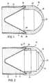
- Die Erfindung wird nachfolgend anhand von zwei in den Zeichnungen dargestellten Ausführungsbeispielen näher erläutert und beschrieben.
- Es zeigen:
- Figur 1
- ein erstes Ausführungsbeispiel einer erfindungsgemäßen Geschoßhaube an einem auszugsweise nur vorderseitig dargestellten Geschoßgehäuse und
- Figur 2
- ein weiteres erfindungsgemäßes Ausführungsbeispiel.
- In Figur 1 ist mit der Bezugsziffer 10 ein beispielhaft nur vorderseitig dargestelltes dünnwandiges zylindrisches Geschoßgehäuse bezeichnet. Innerhalb des Geschoßgehäuses 10 ist als Wirkteil eine Sprengstoffladung 12 und eine Hohlladungseinlage 14 eingelagert. Die Hohlladungseinlage 14 kann eine beliebige Form aufweisen; sie kann z. B. als Spitzkegel oder Flachkegel oder für eine P-Ladungseinlage kugelkalottenförmig ausgebildet sein.
- Die Hohlladungseinlage 14 schließt vorne bündig mit dem Geschoßgehäuse 10 ab. Das mit einem rückseitigen Geschoßzünder versehene, nach vorne offene Geschoßgehäuse 10 ist vorderseitig mit einer spitzenseitig gewölbten Haube 16 verschlossen. Im Bereich 18 der vorderseitigen Krümmung weist die Haube 16 eine zum vorderen Haubenmittelpunkt 20 kontinuierlich abnehmende Wandstärke auf, die bei Zielaufprall eine gewisse begrenzte Deformation zuläßt.
- An den vorderseitigen Krümmungsbereich 18 schließt sich bis zum Geschoßgehäuse 10 ein zylindrisches Ansatzstück 22 der Haube 16 an. Das zylindrische Ansatzstück 22 weist eine dickere Wandstärke als das Geschoßgehäuse 10 auf und wird bei Zielaufprall nicht deformiert. Vorzugsweise weist das zylindrische Ansatzstück 22 die dreifache Wandstärke des Geschoßgehäuses 10 auf. Das zylindrische Ansatzstück 22 gewährleistet dadurch als Abstützung einen festen Sitz für den inneren Wirkteil und einen ausreichenden Zündabstand (stand-off) der Hohlladungseinlage vor dem Ziel zur Ausbildung eines leistungsfähigen Durchdringungsstachels.
- Im Verbindungsbereich mit dem Geschoßgehäuse 10 weist die Haube 16 bzw. das zylindrische Ansatzstück 22 ein nach hinten weisendes äußeres Ringteil 24 von größerem Durchmesser als das Geschoßgehäuse 10, ein nach hinten weisendes inneres Ringteil 26 von kleinerem Durchmesser als das Geschoßgehäuse 10 und eine dazwischenliegende, nach vorne weisende ringförmige Ausnehmung 28 im Verbindungsbereich mit dem Geschoßgehäuse 10 als gemeinsame Abstützung für die Sprengstoffladung 12 und die Hohlladungseinlage 14 auf.
- Für eine Fixierung der Haube 16 mit dem Geschoßgehäuse 10 ist in der Außenwandung des Geschoßgehäuses 10 im vorderen Verbindungsbereich eine umlaufende Nut 30 vorgesehen, in die der Rand des nach hinten weisenden äußeren Ringteiles 24 der Haube 16 eingebördelt oder eingerollt ist.
- Die Befestigung der Haube 16 mit dem Geschoßgehäuse 10 kann in anderer Ausführung auch dadurch erfolgen, daß der Durchmesser der Haube kleiner als der Durchmesser des Geschoßgehäuses gehalten ist und das Geschoßgehäuse geringfügig nach vorne über die Hohlladungseinlage verlängert ist. Wenn nun die Haube im Befestigungsbereich eine umlaufende Nut aufweist, kann der vorstehende Rand des Geschoßgehäuses in diese Nut der Haube eingebördelt werden.
- In Figur 2 ist eine andere Ausführung der Haube 16 in fertigungstechnisch einfacher Form dargestellt. Hierbei nimmt die Wandstärke der Haube 16 im gekrümmten Bereich von hinten nach vorne stufenweise ab.
- Bei einem Haubenrohling aus Aluminium, vorzugsweise aus einer Aluminiumlegierung mit einer Zugfestigkeit von wenigstens 28 kp/mm², wird durch einen ersten Arbeitsgang die innere Wandung im zylindrischen Ansatzstück 22 mit vorgegebenen Durchmesser ausgedreht, durch einen zweiten Arbeitsgang, z. B. mit einem Kegelfräser oder entsprechend kegelförmig ausgebildetem Bohrer, ergibt sich eine kegelförmige zentrale Ausdrehung 40 der vorderen inneren Haubenwandung mit mehreren Schwachstellen die von vorne nach hinten eine zunehmende Stärke aufweisen, so daß eine vorgebbare Deformierung der Haube im gekrümmten Bereich bei hartem Zielaufprall mit Aufprallabminderung und Aufzehrung der nachteiligen Stoßenergie für die inneren Bauteile des Geschosses gewährleistet ist.
- Zur Verbesserung der Abstützwirkung des inneren Ringteiles der Haube 16 für den inneren Wirkteil ist ein innen eingesetztes ringförmiges Einsatzstück 36 vorgesehen, das vorzugsweise aus einer Aluminiumlegierung mit einer Zugfestigkeit von wenigstens 52 kp/mm² besteht.
- Die Haube 16 kann auch aus Kunststoff ausgeführt sein. Dann ist die jeweilige Wandstärke entsprechend der Materialfestigkeit angepaßt auszuführen. Hierbei bietet sich ebenfalls bei einer Kunststoffausführung der Haube die Verwendung des ringförmigen Einsatzstückes 36, z. B. aus Aluminium oder einem festeren Material an.
Claims (7)
- Hohlladungsgeschoß mit zylindrischem Geschoßgehäuse (10), darin eingelagerter Sprengstoffladung (12), Zünder, Hohlladungseinlage (14) und einer vorderseitigen, das nach vorne offene Geschoßgehäuse (10) verschließenden Haube (16), wobei die Haube (16) im Bereich (18) ihrer vorderseitigen Krümmung von einem nach hinten weisenden zylindrischen Ansatzstück (22) bis zum vorderen Haubenmittelpunkt (20) eine abnehmende Wandstärke aufweist, dadurch gekennzeichnet, daß die Wandstärkenverminderung zwischen dem zylindrischen Ansatzstück (22) und dem vorderen Haubenmittelpunkt (20) derart gewählt ist, daß die Haube (16) sich bei Zielaufprall in vorgegebener Weise deformiert, und daß das zylindrische Ansatzstück (22) der Haube (16) ein nach hinten weisendes äußeres Ringteil (24) von größerem Durchmesser als das Geschoßgehäuse (10), ein nach hinten weisendes inneres Ringteil (26) von kleinerem Durchmesser als das Geschoßgehäuse (10) und eine dazwischenliegende nach vorne weisende ringförmige Ausnehmung (28) im Verbindungsbereich mit dem Geschoßgehäuse (10) als gemeinsame Abstützung für die Sprengstoffladung (12) und die Hohlladungseinlage (14) aufweist.
- Hohlladungsgeschoß nach Anspruch 1, dadurch gekennzeichnet, daß das nach hinten weisende zylindrische Ansatzstück (22) der Haube (16) eine Wandstärke von etwa dem Dreifachen der Geschoßgehäusewandung aufweist.
- Hohlladungsgeschoß nach Anspruch 1 oder 2, dadurch gekennzeichnet, daß das innere Ringteil (26) der Haube (16) als ein in die Haube (16) eingesetztes ringförmiges Einsatzstück (36) als Abstützung für die Sprengstoffladung (12) und die Hohlladungseinlage (14) ausgebildet ist.
- Hohlladungsgeschoß nach Anspruch 1, 2 oder 3, dadurch gekennzeichnet, daß die Wandstärke der Haube (16) im gekrümmten Bereich (18) von hinten nach vorne stufenweise abnimmt.
- Hohlladungsgeschoß nach Anspruch 1, 2, 3 oder 4, dadurch gekennzeichnet, daß eine zentrale Ausdrehung (40) der inneren Haubenwandung kegelförmig ausgebildet ist.
- Hohlladungsgeschoß nach einem der vorhergehenden Ansprüche 1 bis 5, dadurch gekennzeichnet, daß die Haube (16) aus einer Aluminiumlegierung mit einer Zugfestigkeit von wenigstens 28 kp/mm² und das innere ringförmige Einsatzstück (36) aus einer Aluminiumlegierung mit einer Zugfestigkeit von wenigstens 52 kp/mm² besteht.
- Hohlladungsgeschoß nach einem der vorhergehenden Ansprüche 1 bis 6, dadurch gekennzeichnet, daß die äußere Geschoßgehäusewandung vorderseitig eine umlaufende Ringnut (30) aufweist in die das nach hinten weisende äußere Ringteil (24) der Haube (16) zur gegenseitigen Fixierung einformbar ist.
Applications Claiming Priority (2)
| Application Number | Priority Date | Filing Date | Title |
|---|---|---|---|
| DE3823908 | 1988-07-14 | ||
| DE3823908A DE3823908A1 (de) | 1988-07-14 | 1988-07-14 | Hohlladungsgeschoss |
Publications (2)
| Publication Number | Publication Date |
|---|---|
| EP0352407A1 EP0352407A1 (de) | 1990-01-31 |
| EP0352407B1 true EP0352407B1 (de) | 1992-11-04 |
Family
ID=6358682
Family Applications (1)
| Application Number | Title | Priority Date | Filing Date |
|---|---|---|---|
| EP19890107246 Expired - Lifetime EP0352407B1 (de) | 1988-07-14 | 1989-04-21 | Hohlladungsgeschoss |
Country Status (4)
| Country | Link |
|---|---|
| US (1) | US4945835A (de) |
| EP (1) | EP0352407B1 (de) |
| DE (2) | DE3823908A1 (de) |
| NO (1) | NO891719L (de) |
Families Citing this family (6)
| Publication number | Priority date | Publication date | Assignee | Title |
|---|---|---|---|---|
| SE468687B (sv) * | 1991-06-18 | 1993-03-01 | Bofors Ab | Saett och anordning foer avtaetning av spraengladdningsutrymmet i en granat |
| US8943972B1 (en) * | 2011-10-06 | 2015-02-03 | The United States Of America As Represented By The Secretary Of The Army | Liner release mechanism for anti-armor munitions |
| CN112444164A (zh) * | 2019-09-03 | 2021-03-05 | 南京理工大学 | 高效毁伤的聚能装药超空泡射弹战斗部 |
| EP4441460A2 (de) * | 2021-12-03 | 2024-10-09 | River Front Services, Inc. | Geschossangetriebene explosive struktur |
| GB2619905A (en) * | 2022-03-11 | 2023-12-27 | Thor Ind Ltd | Payload delivery device |
| CN121675825A (zh) * | 2026-02-11 | 2026-03-17 | 四川百吉信石油科技有限公司 | 一种油气井射孔高熵含能定向赋能器及射孔方法 |
Family Cites Families (16)
| Publication number | Priority date | Publication date | Assignee | Title |
|---|---|---|---|---|
| BE475572A (de) * | 1941-10-03 | |||
| DE866318C (de) * | 1941-10-03 | 1953-02-09 | Sageb Sa De Gestion Et D Expl | Geschoss mit Hohlladung |
| FR1002092A (fr) * | 1946-07-25 | 1952-03-03 | Soc Tech De Rech Ind | Perfectionnements aux projectiles perforants |
| US2603155A (en) * | 1947-06-12 | 1952-07-15 | Richard G Clarke | Shock wave actuated photoflash bomb |
| US3002455A (en) * | 1955-04-12 | 1961-10-03 | Bofors Ab | Ballistic missile |
| BE548003A (de) * | 1955-05-20 | 1900-01-01 | ||
| US3188955A (en) * | 1961-03-31 | 1965-06-15 | Western Co Of North America | Explosive charge assemblies |
| US3137233A (en) * | 1962-02-23 | 1964-06-16 | Henry S Lipinski | Explosive confinement ring |
| GB1051407A (en) * | 1964-07-08 | 1966-12-14 | Director General Of Fírsvarets Fabriksstyrelse. | Improvements in or relating to High-explosive Armour piercing Shells |
| LU47107A1 (de) * | 1964-10-08 | 1966-04-08 | ||
| US3485460A (en) * | 1968-02-19 | 1969-12-23 | Avco Corp | Variable drag ogive |
| DE2232955A1 (de) * | 1972-07-05 | 1974-01-17 | Dynamit Nobel Ag | Sicherungsring |
| US3922967A (en) * | 1974-03-29 | 1975-12-02 | Avco Corp | Closed-breech-gun-fired rocket-assisted projectile |
| US4108073A (en) * | 1975-02-27 | 1978-08-22 | The United States Of America As Represented By The Secretary Of The Air Force | Armor piercing projectile |
| GB1550340A (en) * | 1976-10-01 | 1979-08-15 | Allbrown Universal Components | Frenching charge case |
| DE3441693C1 (de) * | 1984-11-15 | 1986-02-06 | Messerschmitt-Bölkow-Blohm GmbH, 8012 Ottobrunn | Vorrichtung zur Kompensation der Waermeausdehnung eines Bauteils |
-
1988
- 1988-07-14 DE DE3823908A patent/DE3823908A1/de not_active Withdrawn
-
1989
- 1989-04-21 DE DE8989107246T patent/DE58902603D1/de not_active Expired - Fee Related
- 1989-04-21 EP EP19890107246 patent/EP0352407B1/de not_active Expired - Lifetime
- 1989-04-25 NO NO89891719A patent/NO891719L/no unknown
- 1989-06-28 US US07/373,683 patent/US4945835A/en not_active Expired - Fee Related
Also Published As
| Publication number | Publication date |
|---|---|
| DE3823908A1 (de) | 1990-01-18 |
| DE58902603D1 (de) | 1992-12-10 |
| US4945835A (en) | 1990-08-07 |
| EP0352407A1 (de) | 1990-01-31 |
| NO891719L (no) | 1990-01-15 |
| NO891719D0 (no) | 1989-04-25 |
Similar Documents
| Publication | Publication Date | Title |
|---|---|---|
| DE2727970C2 (de) | ||
| DE1428679C1 (de) | Hartkerngeschoss zur Bekaempfung von Panzerzielen | |
| EP0291845B1 (de) | Geschoss mit einem Geschosskern und einem Geschossmantel | |
| DE3209594C2 (de) | ||
| DE68906517T2 (de) | Hochleistungsprojektil. | |
| DE3012907A1 (de) | Uebungsgranate, insbesondere fuer ausbildungszwecke | |
| DE2703638A1 (de) | Panzerbrechgeschoss | |
| DE69909719T2 (de) | Bremsvorrichtung für die Flugbahngeschwindigkeit eines Geschosses | |
| DE3781874T2 (de) | Bombe mit splitterhuelle. | |
| DE2824703C2 (de) | Geschoß mit einem Durchschlagkörper | |
| EP0352407A1 (de) | Hohlladungsgeschoss | |
| EP0989381B1 (de) | Unterkalibergeschoss | |
| DE1910779A1 (de) | Verbesserungen in bezug auf die wirksamkeit von hohlladungen | |
| DE2804311A1 (de) | Jagdgeschoss, insbesondere fuer grosswild | |
| DE602004007080T2 (de) | Panzergeschoss | |
| CH660627A5 (de) | Hohlladung. | |
| EP0485897B1 (de) | Bahnkorrigierbares Projektil | |
| DE1165457B (de) | Scheibenstand-Patrone | |
| DE2901500A1 (de) | Sprengladung mit einlage fuer panzerdurchschlag | |
| DE19752102B4 (de) | Panzerbrechendes Geschoß mit Wuchtwirkung | |
| DE3933442C2 (de) | ||
| DE4018385C2 (de) | Unterkalibriges Wuchtgeschoß für Übungszwecke | |
| DE69907791T2 (de) | Bausatz zum Umrüsten eines Sprenggeschosses auf ein Bentonstrukturen brechendes Geschoss, sowie ein derart umgerüstetes Geschoss | |
| EP3845853B1 (de) | Projektil und munition | |
| DE3932825C2 (de) |
Legal Events
| Date | Code | Title | Description |
|---|---|---|---|
| PUAI | Public reference made under article 153(3) epc to a published international application that has entered the european phase |
Free format text: ORIGINAL CODE: 0009012 |
|
| 17P | Request for examination filed |
Effective date: 19891130 |
|
| AK | Designated contracting states |
Kind code of ref document: A1 Designated state(s): CH DE FR GB LI SE |
|
| 17Q | First examination report despatched |
Effective date: 19910826 |
|
| GRAA | (expected) grant |
Free format text: ORIGINAL CODE: 0009210 |
|
| AK | Designated contracting states |
Kind code of ref document: B1 Designated state(s): CH DE FR GB LI SE |
|
| PG25 | Lapsed in a contracting state [announced via postgrant information from national office to epo] |
Ref country code: FR Effective date: 19921104 |
|
| GBT | Gb: translation of ep patent filed (gb section 77(6)(a)/1977) | ||
| REF | Corresponds to: |
Ref document number: 58902603 Country of ref document: DE Date of ref document: 19921210 |
|
| REG | Reference to a national code |
Ref country code: CH Ref legal event code: PFA Free format text: RHEINMETALL GMBH |
|
| RAP4 | Party data changed (patent owner data changed or rights of a patent transferred) |
Owner name: RHEINMETALL GMBH |
|
| PGFP | Annual fee paid to national office [announced via postgrant information from national office to epo] |
Ref country code: SE Payment date: 19930324 Year of fee payment: 5 |
|
| EN | Fr: translation not filed | ||
| PGFP | Annual fee paid to national office [announced via postgrant information from national office to epo] |
Ref country code: CH Payment date: 19930420 Year of fee payment: 5 |
|
| PLBE | No opposition filed within time limit |
Free format text: ORIGINAL CODE: 0009261 |
|
| STAA | Information on the status of an ep patent application or granted ep patent |
Free format text: STATUS: NO OPPOSITION FILED WITHIN TIME LIMIT |
|
| 26N | No opposition filed | ||
| PG25 | Lapsed in a contracting state [announced via postgrant information from national office to epo] |
Ref country code: SE Effective date: 19940422 |
|
| PG25 | Lapsed in a contracting state [announced via postgrant information from national office to epo] |
Ref country code: LI Effective date: 19940430 Ref country code: CH Effective date: 19940430 |
|
| REG | Reference to a national code |
Ref country code: CH Ref legal event code: PL |
|
| EUG | Se: european patent has lapsed |
Ref document number: 89107246.4 Effective date: 19941110 |
|
| REG | Reference to a national code |
Ref country code: GB Ref legal event code: IF02 |
|
| PGFP | Annual fee paid to national office [announced via postgrant information from national office to epo] |
Ref country code: DE Payment date: 20060419 Year of fee payment: 18 |
|
| PGFP | Annual fee paid to national office [announced via postgrant information from national office to epo] |
Ref country code: GB Payment date: 20060420 Year of fee payment: 18 |
|
| GBPC | Gb: european patent ceased through non-payment of renewal fee |
Effective date: 20070421 |
|
| PG25 | Lapsed in a contracting state [announced via postgrant information from national office to epo] |
Ref country code: DE Free format text: LAPSE BECAUSE OF NON-PAYMENT OF DUE FEES Effective date: 20071101 |
|
| PG25 | Lapsed in a contracting state [announced via postgrant information from national office to epo] |
Ref country code: GB Free format text: LAPSE BECAUSE OF NON-PAYMENT OF DUE FEES Effective date: 20070421 |