EP0350723B1 - Ventil zum Anschliessen von Objekten an vor Ort zu sterilisierenden Behältern oder Leitungen - Google Patents
Ventil zum Anschliessen von Objekten an vor Ort zu sterilisierenden Behältern oder Leitungen Download PDFInfo
- Publication number
- EP0350723B1 EP0350723B1 EP89111845A EP89111845A EP0350723B1 EP 0350723 B1 EP0350723 B1 EP 0350723B1 EP 89111845 A EP89111845 A EP 89111845A EP 89111845 A EP89111845 A EP 89111845A EP 0350723 B1 EP0350723 B1 EP 0350723B1
- Authority
- EP
- European Patent Office
- Prior art keywords
- valve
- container
- opening
- interior
- sterilisable
- Prior art date
- Legal status (The legal status is an assumption and is not a legal conclusion. Google has not performed a legal analysis and makes no representation as to the accuracy of the status listed.)
- Expired - Lifetime
Links
Images


Classifications
-
- A—HUMAN NECESSITIES
- A61—MEDICAL OR VETERINARY SCIENCE; HYGIENE
- A61L—METHODS OR APPARATUS FOR STERILISING MATERIALS OR OBJECTS IN GENERAL; DISINFECTION, STERILISATION OR DEODORISATION OF AIR; CHEMICAL ASPECTS OF BANDAGES, DRESSINGS, ABSORBENT PADS OR SURGICAL ARTICLES; MATERIALS FOR BANDAGES, DRESSINGS, ABSORBENT PADS OR SURGICAL ARTICLES
- A61L2/00—Disinfection or sterilisation of materials or objects, in general; Accessories therefor
- A61L2/26—Accessories
-
- C—CHEMISTRY; METALLURGY
- C12—BIOCHEMISTRY; BEER; SPIRITS; WINE; VINEGAR; MICROBIOLOGY; ENZYMOLOGY; MUTATION OR GENETIC ENGINEERING
- C12M—APPARATUS FOR ENZYMOLOGY OR MICROBIOLOGY; APPARATUS FOR CULTURING MICROORGANISMS FOR PRODUCING BIOMASS, FOR GROWING CELLS OR FOR OBTAINING FERMENTATION OR METABOLIC PRODUCTS, i.e. BIOREACTORS OR FERMENTERS
- C12M37/00—Means for sterilizing, maintaining sterile conditions or avoiding chemical or biological contamination
Definitions
- the invention relates to a sterilizable object, such as a container or line, with a connecting valve which has an outer connection opening, a valve housing which can be sealingly attached to a connection opening of the object and which has a seat opening leading to the interior of the object, and which is guided so that it can be moved radially sealed between a blocking position and a passage position Has valve stem.
- Containers for example bioreactors, in which substances are stored and / or changed in work processes under sterile conditions, must have connection openings for sampling, for metering in various reagents and for harvesting.
- the objects to be connected must also be mounted under sterile conditions.
- a method is widespread in which a tightly clamped elastomer molding seals the sterilized container as a membrane on a special piercing nozzle of the container. This membrane is pierced by hand with a likewise sterilized pointed hollow needle, thus creating a sterile connection between the inside and the outside.
- the needle when and after removing the piercing needle from the autoclave with connected accessories such as a hose line, the needle is not contaminated with microorganisms In the non-sterile environment, this needle is wrapped with a suitable film before sterilization or wrapped in it and tightly glued.
- a sleeve with a built-in microfilter that is pushed over the needle is and is also known under the name "sterile sleeve".
- the foil or sterile sleeve must be removed by hand immediately before piercing.
- the membrane and piercing needle In order to avoid contamination of the object to be pierced, the membrane and piercing needle must be kept sterile after unpacking until they are pierced with flames. This is the riskiest phase of the known way of working.
- connection line is also kept under sterile conditions when it comes to metering in reagents, and complex line installations with corresponding valves must be provided so that the peripheral connection lines are sterilized can.
- the disadvantage is that, especially in laboratories, the steam required for this is not readily available and therefore additional investments for the corresponding infrastructure are necessary. If the connection to the container is made by means of a hollow needle by pushing it through the membrane, one has to accept the increased risk of contamination of the container contents and the environment. Piercing containers in the area below the liquid level, ie directly into the liquid, is particularly risky. The membrane is pierced at all in hazardous areas not applicable. For example, once a fermenter has been pierced, it can no longer be sterilized because the perforated membrane and the fermenter can then no longer be sterilized. It is also disadvantageous that piercing the membrane is too risky for pathogenic applications.
- EP 295 408 A2 describes a valve which leads through an outer wall of a bioreactor vessel.
- the valve enables steam sterilization of the interior of the reactor vessel and of the tubes projecting below the liquid level of the reactor vessel.
- the valve has a valve spindle provided with an axially continuous bore. It is disadvantageous that the valve does not allow the container to be hermetically sealed, since it is only suitable for optionally establishing a connection to the reactor vessel or to an immersion tube arranged in the reactor vessel.
- the valve is used with a three / two-way valve arranged below.
- a device for sterile sampling in microbiological processes which has a steam sterilization system with a condenser and a hermetically sealed sampling vessel provided with a connection valve. After sterilization in an autoclave, the sample vessel and the valve are connected to an intermediate chamber. The sample container with valve can be detached from the intermediate chamber and transported away for further treatment of the sample.
- a high pressure valve with a radially sealed displaceably guided valve spindle which can be switched between an emptying and passage position.
- the valve spindle which is axially provided with a blind bore, has two side openings opening into its peripheral surfaces. Furthermore, a valve chamber adjoining the peripheral surface of the valve spindle and an emptying chamber are arranged in the valve housing.
- the disadvantage is that the valve is only used to relieve high-pressure liquids, with both valve connecting lines being relieved against ambient pressure in the emptying position.
- a sterilizable object such as a container or line, with a connecting valve
- a connecting valve which has an outer connection opening
- a valve housing which can be sealingly attached to a connection opening of the object and leads to the interior of the object Seat opening, which has a radially sealingly displaceable valve spindle between a blocking position and a passage position. Seals Valve disc with radial seal in the closed position from the drain or feed opening.
- the object of the invention is to provide another valve design that has a particularly small dead corner for applications in biotechnology, so that the risk of contamination is reduced.
- valve designs can serve simultaneously as a shut-off valve and as a changeover valve for connection to an immersion tube. They can therefore be used particularly universally for the needs of biotechnology. This universal application means that the number of valves on bioreactors can be reduced, which not only achieves cost advantages, but also reduces the risk of contamination of valuable batches.
- valves It is possible to first mount the valve under non-sterile conditions.
- the object to be connected is sterilized, i.e. only after the special connection valves have been firmly and tightly mounted on them in the closed state.
- the still non-sterile valve sections are sterilized with the object itself. It is irrelevant whether the connected valves are below or above the liquid level.
- the connection valves are only opened and put into operation after the connected objects have been sterilized on site. This means that these valves can also be used in potentially explosive areas.
- valves can be differentiated in terms of their opening direction. There are also significant differences as to whether a valve chamber is provided or not.
- the connection opening can either be guided by a plunger or can be connected directly to a valve chamber.
- connection valve has a connection to an immersion tube. It is thus possible for the end of the valve spindle facing away from the container interior to be arranged so as to be movable within an immersion tube and to be sealed off from it at least in the passage position. As a result, the valve can also be connected to immersion pipes in a particularly inexpensive manner without great design effort.
- the seal ensures that the valves do not have to be arranged below the liquid level for removal purposes, since the seal also seals against negative pressure.
- the valve housing it is possible for the valve housing to be designed as a tubular extension projecting into the container with lateral openings, which at the end has a coupling for mounting an immersion tube.
- valve stem is sealed at least two points from the valve housing, so that the seals form a space around the stem, in which one or more holes are arranged opening.
- security can advantageously be increased by passing a sterilizing medium through the barrier space even during the process and / or superimposing it with pressure.
- connection valve has a connection to a check valve opening in the direction of the container.
- a check valve is realized in an advantageously simple and inexpensive manner.
- a leak occurs in the pressure area of the dosing line, as can happen, for example, when the hose of a hose pump is worn through. The supply pressure then falls. Since the container is usually operated with excess pressure, this leads to a backlash of process liquid or process exhaust gas, depending on the location of the valve. The associated consequences are advantageously avoided by the check valve.
- valve housing is arranged within an installation part, which is preferably tubular and has an outer collar at one end and an external thread for a union nut or screw at the other end, serves for easier assembly.
- installation part has an opening with an internal thread with a collar, into which the screw with the valve is screwed.
- a collar formed on the valve is tensioned by the screw against the collar of the opening.
- valve spindle, the valve housing and the installation part are arranged to form the valve chamber.
- the seal between the valve spindle and the valve housing on the side facing away from the container interior is a membrane seal.
- This type of seal has the advantage that the sealing points are immobile. In other words, there are no seals against the non-sterile environment that slide on sealing surfaces. Leakage losses can thereby be reduced. This is particularly advantageous if the valve is actuated several times during a work process. This applies in particular if the membrane seal is a bellows or an elastic hose.
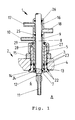
- connection valve according to the invention is designated by 1 and by 2 a sterilizable container.
- the sterilizable container 2 has openings 3 in its container wall 4.
- the valve 1 has a valve housing 5 which, in the installed position to the interior 6 of the container, opens into a seat opening 7, in which the valve spindle 8 is arranged to be axially displaceable.
- the valve chamber 9, into which an outer connection opening 10 opens, is formed by valve housing 5 and valve spindle 8.
- the valve tappet 8 has a through bore 11 in its lower part, which connects two lateral openings 12 and the opening in the end face of the valve spindle 8.
- an installation part 13 is arranged between the container 2 and valve 1, which is inserted from the container interior 6 into the connection opening 3 up to the stop 14.
- the mounting part 13 is clamped to the container wall 4 by means of nut 15, which is screwed onto a thread of the mounting part 13
- valve chamber 9 there is also a blocking chamber 16 arranged in an annular manner around the valve tappet 8 with an inlet opening 17 and an outlet opening 18.
- the seals 22 seal the container and the valve housing against the interior of the container.
- the seals 23 serve to seal the flushing opening or the opening and the bore in the container wall.
- the seal 24 seals the valve chamber 9 from the container interior 6; while the seal 25 seals the valve chamber 9 to the outside.
- the seal 26 is provided so that the sealing chamber is sealed both to the outside and to the valve chamber 9 by the seals 26 and 25.
- the valve is inserted into a cylindrical bore of the mounting part 13 and clamped to it by means of the union nut 27, which has the same thread as the nut 15.
- the union nut 27 is rotatably held between the collar 28 of the valve housing and the locking ring 29.
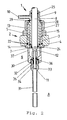
- Fig. 2 shows the connection valve according to the invention as a section with an additional bracket 30 on the mounting part 13 for fastening an immersion tube 31.
- the mounting part 13 is extended to the interior of the container 6 and provided with a thread 32 at its end, into the insertion end 33 of the immersion tube 31 can be screwed in.
- the valve spindle 8 has a section 34 with a larger and section 35 with a smaller diameter at its end facing the container interior 6.
- both sections of the valve tappet end are inside the dip tube 31.
- section 35 of the valve tappet end is outside the dip tube, the seal 36 then between section 34 and the dip tube is arranged.
- the immersion tube holder has openings 37 so that the space between the holder and valve tappet in the blocking position A can be reached by sterilizing media.
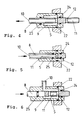
- Fig. 3 shows a different kind of design of the dip tube attachment.
- the dip tube 31 is inserted into the passage opening 11 of the valve lifter 8.
- the valve tappet 8 has a thread 38 for the union nut at its end facing the interior 6 of the container 39 on.
- a pinch seal 40 is inserted between the end of the valve lifter and the union nut 39. By tightening the union nut 39, the seal 40 is compressed between the end of the valve tappet and the union nut 39, so that it is supported on the dip tube 31 and thereby firmly connects the dip tube to the valve tappet 8.
- Fig. 4 shows a section through the valve according to the invention as an inline version. This design differs from the corner valve-like designs described above in that the connection is made coaxially with the valve spindle 8 via the connection opening 10.
- the valve spindle 8 has a coaxial guided bore which opens into two lateral outlet openings within the valve chamber 9. The arrow indicates the direction in which the valve stem is moved to open.
- FIG. 5 shows a section through a further inline version which, in contrast to the previously described embodiments, is designed without a valve chamber. This results in an advantageously small valve volume, which can be sterilized more easily.
- the valve spindle has only a single through-bore 11, which opens into two lateral openings 12. In the locked position, the openings 12 are closed by the valve housing 5.
- the rings 24 and 25 which seal the openings 12 laterally are not arranged inside the valve housing, as in the cases described above, but on the valve spindle. To open the valve, the valve spindle is moved in the direction of the arrow towards the inside of the container. This embodiment leaves produce themselves with an advantageously low technical manufacturing effort.
- Figure 6 shows a section through another embodiment of the valve according to the invention, which is designed as a corner valve, but as in Figure 6 is moved to open in the direction of the arrow towards the interior of the container in the direction of the arrow.
- the valve spindle 8 has a through hole 11 in a partial area, which opens on both sides in lateral openings 12 within the valve chamber 9.
- the valve chamber is sealed off from the container by a ring 24 arranged inside the housing.
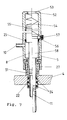
- Figure 7 shows a valve design that opens automatically as soon as a medium is supplied under pressure.
- the valve is drawn in the through position to the left of the dash-dotted line and to the right of the line in the blocking position.
- the valve housing 5 is fastened by means of a union nut 27 on an externally threaded connecting piece 51 of the container.
- the valve tappet 8 in this embodiment which is designed as a corner valve, is shaped as a piston 58 at its end facing away from the container. On the outer surface of the piston 58 there is a locking groove 55 into which the ball 56 engages in the locking position by means of the spring 57.
- a spring 54 is arranged, which presses the piston 58 with valve tappet 8 automatically into the blocking position shown on the right of the dash-dotted line as soon as no pressure is present in the valve chamber. So that the piston 58 at his Hub builds up no back pressure within the valve housing, the valve housing 5 is vented through the opening 53.
- the valve is actuated by supplying a medium under pressure through the connection opening 10. Due to the larger area of the piston-like end 58 of the valve spindle 8, the valve spindle is moved from the position shown on the right by the dash-dotted line to the position shown on the left of the line. It presses the ball 56 against the force of the spring 57 out of the locking groove 55. As soon as the through-bore 11 communicates with the valve chamber, the pressure built up in the valve chamber decreases to such an extent that the piston 58 comes to a standstill in the equilibrium position.
- valve 8 shows a valve variant in which, unlike the variants described above, the valve chamber 9 is formed on the outside by the mounting part 13, on the top by the end face of the valve housing 5 and below by a collar on the valve tappet 8.
- the through position of the valve is shown to the left of the dash-dotted center line, while the valve is shown in the blocking position to the right of the dash-dotted center line. All seals are designed as external O-rings, so that the valve can be produced particularly inexpensively even for small diameters.
- valves according to the invention function as follows: In the position A shown in FIG. 1, the valve hermetically seals off the container interior 6 from the outside. In this position, the container interior is sterilized on site. The through hole 11 and the lateral openings 12 are located inside the container. By actuating the valve spindle 8 out of the container interior, the lateral bores 12 are moved until they are located within the valve chamber 9. The valve chamber 9 then communicates with the container interior 6 via the lateral openings 12 and the through bore 11. In this position, a substance can be metered into a batch in the container via the connection opening 10, or, depending on the installation location of the valve, substances from the Container interior are deducted. For special applications, a blocking chamber 16 can also be provided, through which a sterilizing medium, preferably under pressure, is continuously passed or introduced through the openings 17, 18. Contamination of the outside world can be safely prevented.
- the holder 30 for the immersion tube can either be firmly connected to the container or, as shown, to the installation part or else to the valve housing. In all cases, the dip tube remains stationary relative to the container.
- a solution can also be chosen, as shown in FIG. 3, in which the immersion tube 31 is fixedly connected to the valve tappet and thus moves with the valve tappet relative to the container.
- the movement can also be force-actuated by cylinders or electric linear drives which are connected to the valve spindle 8.
- this sliding seal can also be replaced by a membrane seal which is firmly held in the valve housing 5 on one side and is connected to the valve stem 8 on the other side.
- a membrane seal which is firmly held in the valve housing 5 on one side and is connected to the valve stem 8 on the other side.
- such a seal can be designed to be elastic, either as a bellows or as a hose.
Landscapes
- Health & Medical Sciences (AREA)
- Life Sciences & Earth Sciences (AREA)
- Wood Science & Technology (AREA)
- Organic Chemistry (AREA)
- Engineering & Computer Science (AREA)
- Bioinformatics & Cheminformatics (AREA)
- General Health & Medical Sciences (AREA)
- Chemical & Material Sciences (AREA)
- Zoology (AREA)
- Biochemistry (AREA)
- Animal Behavior & Ethology (AREA)
- Microbiology (AREA)
- Biotechnology (AREA)
- General Engineering & Computer Science (AREA)
- Biomedical Technology (AREA)
- Genetics & Genomics (AREA)
- Molecular Biology (AREA)
- Epidemiology (AREA)
- Sustainable Development (AREA)
- Public Health (AREA)
- Veterinary Medicine (AREA)
- Apparatus For Disinfection Or Sterilisation (AREA)
- Food Preservation Except Freezing, Refrigeration, And Drying (AREA)
- Packages (AREA)
- Check Valves (AREA)
- Cosmetics (AREA)
- Quick-Acting Or Multi-Walled Pipe Joints (AREA)
Applications Claiming Priority (2)
| Application Number | Priority Date | Filing Date | Title |
|---|---|---|---|
| DE3823711A DE3823711C1 (enExample) | 1988-07-13 | 1988-07-13 | |
| DE3823711 | 1988-07-13 |
Publications (3)
| Publication Number | Publication Date |
|---|---|
| EP0350723A2 EP0350723A2 (de) | 1990-01-17 |
| EP0350723A3 EP0350723A3 (de) | 1991-01-23 |
| EP0350723B1 true EP0350723B1 (de) | 1994-08-10 |
Family
ID=6358576
Family Applications (1)
| Application Number | Title | Priority Date | Filing Date |
|---|---|---|---|
| EP89111845A Expired - Lifetime EP0350723B1 (de) | 1988-07-13 | 1989-06-29 | Ventil zum Anschliessen von Objekten an vor Ort zu sterilisierenden Behältern oder Leitungen |
Country Status (5)
| Country | Link |
|---|---|
| EP (1) | EP0350723B1 (enExample) |
| JP (1) | JPH0277258A (enExample) |
| AT (1) | ATE109684T1 (enExample) |
| DE (2) | DE3823711C1 (enExample) |
| ES (1) | ES2058407T3 (enExample) |
Cited By (3)
| Publication number | Priority date | Publication date | Assignee | Title |
|---|---|---|---|---|
| DE102004045785B3 (de) * | 2004-09-22 | 2006-05-18 | Sartorius Ag | Zugabe- und Probenahmeventil und Verfahren zur sterilen Zugabe von Medien |
| US7942925B2 (en) | 2001-07-09 | 2011-05-17 | Surpass Medical Ltd. | Implantable intraluminal device and method of using same in treating aneurysms |
| US8790641B2 (en) | 2003-04-27 | 2014-07-29 | Protalix Ltd. | Production of high mannose proteins in plant culture and therapeutic uses thereof |
Families Citing this family (7)
| Publication number | Priority date | Publication date | Assignee | Title |
|---|---|---|---|---|
| EP0447256A3 (en) * | 1990-03-16 | 1992-01-08 | Hitachi, Ltd. | Methods and apparatus for incubation and sterilization |
| IL119310A (en) | 1996-09-26 | 1999-07-14 | Metabogal Ltd | Cell/tissue culturing device and method |
| EP1045238A3 (de) * | 1999-04-14 | 2002-09-11 | Nisco Engineering AG | Probeentnahme-Ventil und -Vorrichtung zur verlustarmen Entnahme von Flüssigkeitsproben aus einem Hohlkörper |
| DE202005011194U1 (de) * | 2005-07-13 | 2005-11-03 | Systec Gmbh Labor-Systemtechnik | Gerät zum Sterilisieren und Abfüllen von sterilen flüssigen Medien |
| US20070266601A1 (en) * | 2006-05-19 | 2007-11-22 | Claxton Richard L | Device for measuring a load at the end of a rope wrapped over a rod |
| AU2008246928B2 (en) | 2007-05-07 | 2014-04-17 | Protalix Ltd. | Large scale disposable bioreactor |
| CN110257220B (zh) * | 2019-06-19 | 2024-08-20 | 山东现代畜牧科技有限公司 | 一种用于牛精子过滤式精子分离器 |
Citations (1)
| Publication number | Priority date | Publication date | Assignee | Title |
|---|---|---|---|---|
| DE2609825A1 (de) * | 1976-03-10 | 1977-09-15 | Rintekno Oy | Reaktor fuer biotische reaktionen |
Family Cites Families (3)
| Publication number | Priority date | Publication date | Assignee | Title |
|---|---|---|---|---|
| US4665944A (en) * | 1981-08-10 | 1987-05-19 | Flow Industries, Inc. | On-off dump valve |
| JPS6264793A (ja) * | 1985-09-17 | 1987-03-23 | 協和醗酵工業株式会社 | 無菌液体の循環式送液路の配管 |
| DE3720049A1 (de) * | 1987-06-16 | 1988-12-29 | Braun Melsungen Ag | Bioreaktor |
-
1988
- 1988-07-13 DE DE3823711A patent/DE3823711C1/de not_active Expired - Lifetime
-
1989
- 1989-06-29 DE DE58908171T patent/DE58908171D1/de not_active Expired - Fee Related
- 1989-06-29 ES ES89111845T patent/ES2058407T3/es not_active Expired - Lifetime
- 1989-06-29 EP EP89111845A patent/EP0350723B1/de not_active Expired - Lifetime
- 1989-06-29 AT AT89111845T patent/ATE109684T1/de active
- 1989-07-12 JP JP1180123A patent/JPH0277258A/ja active Pending
Patent Citations (1)
| Publication number | Priority date | Publication date | Assignee | Title |
|---|---|---|---|---|
| DE2609825A1 (de) * | 1976-03-10 | 1977-09-15 | Rintekno Oy | Reaktor fuer biotische reaktionen |
Cited By (4)
| Publication number | Priority date | Publication date | Assignee | Title |
|---|---|---|---|---|
| US7942925B2 (en) | 2001-07-09 | 2011-05-17 | Surpass Medical Ltd. | Implantable intraluminal device and method of using same in treating aneurysms |
| US8419787B2 (en) | 2001-11-23 | 2013-04-16 | Surpass Medical Ltd | Implantable intraluminal device and method of using same in treating aneurysms |
| US8790641B2 (en) | 2003-04-27 | 2014-07-29 | Protalix Ltd. | Production of high mannose proteins in plant culture and therapeutic uses thereof |
| DE102004045785B3 (de) * | 2004-09-22 | 2006-05-18 | Sartorius Ag | Zugabe- und Probenahmeventil und Verfahren zur sterilen Zugabe von Medien |
Also Published As
| Publication number | Publication date |
|---|---|
| DE58908171D1 (de) | 1994-09-15 |
| EP0350723A3 (de) | 1991-01-23 |
| ES2058407T3 (es) | 1994-11-01 |
| JPH0277258A (ja) | 1990-03-16 |
| EP0350723A2 (de) | 1990-01-17 |
| ATE109684T1 (de) | 1994-08-15 |
| DE3823711C1 (enExample) | 1990-04-12 |
Similar Documents
| Publication | Publication Date | Title |
|---|---|---|
| DE4303524C1 (de) | Füllventil für eine Behälterfüllmaschine | |
| EP0350723B1 (de) | Ventil zum Anschliessen von Objekten an vor Ort zu sterilisierenden Behältern oder Leitungen | |
| DE69729828T2 (de) | Zusammenschiebbare vorrichtung zur kompression von packungsmaterial in flüssigkeitschromatographiekolonnen und verfahren zu ihrer benutzung | |
| DE1675538A1 (de) | Ventilaggregat | |
| EP0267935B1 (de) | Ventil für sterilisierbehälter und verfahren zum steueren des ventils | |
| DE2432967C3 (de) | Aseptisches Ventil | |
| DE60037023T2 (de) | Verbindungsset | |
| DE4243111B4 (de) | Aseptische Doppelsitz-Ventilvorrichtung | |
| DE68917751T2 (de) | Flüssigkeitssteuerung und Vorrichtung. | |
| DE102019108664A1 (de) | Sterilverbinder für den sterilen Transfer eines flüssigen Mediums | |
| DE3015830C2 (enExample) | ||
| DE1598595A1 (de) | Gerut zur fraktionierung von zellen | |
| EP0357998B1 (de) | Verfahren für eine sterile Handhabung von strömungsfähigen Fermenterproben sowie Vorrichtung zur Durchführung des Verfahrens. | |
| EP0295408B1 (de) | Bioreaktor | |
| DE825189C (de) | Absperrorgan | |
| CH652144A5 (en) | Appliance for sterile sampling from a fermentation apparatus | |
| DE2814086C2 (de) | Dosierpumpe für Milch u.dgl | |
| DE19652215C2 (de) | Verfahren zum Reinigen eines leckagefrei schaltenden Absperrventils und Absperrventil zur Durchführung des Verfahrens | |
| EP3047195A1 (de) | Kondensatableiter | |
| DE2445780A1 (de) | Druckuebertrager | |
| DE4122724C2 (de) | Sterilbodenablaßventil | |
| WO1992006363A1 (de) | Verfahren und vorrichtung zur probengewinnung und probenhandhabung | |
| EP0044031A1 (de) | Vorrichtung zum Öffnen oder Schliessen einer Tür, insbesondere einer Feuertür | |
| DE19633074B4 (de) | Automatisch verschließbares Leitungsventil | |
| EP1920797A1 (de) | Fluidkanal-Wählschalter mit Rollenklemmen |
Legal Events
| Date | Code | Title | Description |
|---|---|---|---|
| PUAI | Public reference made under article 153(3) epc to a published international application that has entered the european phase |
Free format text: ORIGINAL CODE: 0009012 |
|
| AK | Designated contracting states |
Kind code of ref document: A2 Designated state(s): AT BE CH DE ES FR GB IT LI NL SE |
|
| PUAL | Search report despatched |
Free format text: ORIGINAL CODE: 0009013 |
|
| AK | Designated contracting states |
Kind code of ref document: A3 Designated state(s): AT BE CH DE ES FR GB IT LI NL SE |
|
| 17P | Request for examination filed |
Effective date: 19901227 |
|
| RHK1 | Main classification (correction) |
Ipc: C12M 1/12 |
|
| 17Q | First examination report despatched |
Effective date: 19920217 |
|
| RAP1 | Party data changed (applicant data changed or rights of an application transferred) |
Owner name: B. BRAUN BIOTECH INTERNATIONAL GMBH |
|
| GRAA | (expected) grant |
Free format text: ORIGINAL CODE: 0009210 |
|
| ITF | It: translation for a ep patent filed | ||
| AK | Designated contracting states |
Kind code of ref document: B1 Designated state(s): AT BE CH DE ES FR GB IT LI NL SE |
|
| REF | Corresponds to: |
Ref document number: 109684 Country of ref document: AT Date of ref document: 19940815 Kind code of ref document: T |
|
| REF | Corresponds to: |
Ref document number: 58908171 Country of ref document: DE Date of ref document: 19940915 |
|
| ET | Fr: translation filed | ||
| GBT | Gb: translation of ep patent filed (gb section 77(6)(a)/1977) |
Effective date: 19940818 |
|
| REG | Reference to a national code |
Ref country code: ES Ref legal event code: FG2A Ref document number: 2058407 Country of ref document: ES Kind code of ref document: T3 |
|
| PG25 | Lapsed in a contracting state [announced via postgrant information from national office to epo] |
Ref country code: SE Effective date: 19941110 |
|
| PLBE | No opposition filed within time limit |
Free format text: ORIGINAL CODE: 0009261 |
|
| STAA | Information on the status of an ep patent application or granted ep patent |
Free format text: STATUS: NO OPPOSITION FILED WITHIN TIME LIMIT |
|
| PG25 | Lapsed in a contracting state [announced via postgrant information from national office to epo] |
Ref country code: AT Effective date: 19950629 |
|
| 26N | No opposition filed | ||
| PGFP | Annual fee paid to national office [announced via postgrant information from national office to epo] |
Ref country code: GB Payment date: 20000710 Year of fee payment: 12 |
|
| PGFP | Annual fee paid to national office [announced via postgrant information from national office to epo] |
Ref country code: ES Payment date: 20000721 Year of fee payment: 12 |
|
| PGFP | Annual fee paid to national office [announced via postgrant information from national office to epo] |
Ref country code: BE Payment date: 20000726 Year of fee payment: 12 |
|
| PG25 | Lapsed in a contracting state [announced via postgrant information from national office to epo] |
Ref country code: GB Free format text: LAPSE BECAUSE OF NON-PAYMENT OF DUE FEES Effective date: 20010629 |
|
| PG25 | Lapsed in a contracting state [announced via postgrant information from national office to epo] |
Ref country code: ES Free format text: LAPSE BECAUSE OF NON-PAYMENT OF DUE FEES Effective date: 20010630 Ref country code: BE Free format text: LAPSE BECAUSE OF NON-PAYMENT OF DUE FEES Effective date: 20010630 |
|
| REG | Reference to a national code |
Ref country code: CH Ref legal event code: PUE Owner name: B. BRAUN BIOTECH INTERNATIONAL GMBH TRANSFER- SART |
|
| NLS | Nl: assignments of ep-patents |
Owner name: SARTORIUS AG |
|
| REG | Reference to a national code |
Ref country code: FR Ref legal event code: TP |
|
| BERE | Be: lapsed |
Owner name: B. BRAUN BIOTECH INTERNATIONAL G.M.B.H. Effective date: 20010630 |
|
| GBPC | Gb: european patent ceased through non-payment of renewal fee |
Effective date: 20010629 |
|
| REG | Reference to a national code |
Ref country code: ES Ref legal event code: FD2A Effective date: 20030203 |
|
| PGFP | Annual fee paid to national office [announced via postgrant information from national office to epo] |
Ref country code: NL Payment date: 20070618 Year of fee payment: 19 |
|
| PGFP | Annual fee paid to national office [announced via postgrant information from national office to epo] |
Ref country code: DE Payment date: 20070630 Year of fee payment: 19 |
|
| REG | Reference to a national code |
Ref country code: CH Ref legal event code: PUE Owner name: SARTORIUS BIOTECH GMBH Free format text: SARTORIUS AG#WEENDER LANDSTRASSE 94-103#37075 GOETTINGEN (DE) -TRANSFER TO- SARTORIUS BIOTECH GMBH#AUGUST-SPINDLER-STRASSE 11#37079 GOETTINGEN (DE) |
|
| REG | Reference to a national code |
Ref country code: CH Ref legal event code: PFA Owner name: SARTORIUS STEDIM BIOTECH GMBH Free format text: SARTORIUS BIOTECH GMBH#AUGUST-SPINDLER-STRASSE 11#37079 GOETTINGEN (DE) -TRANSFER TO- SARTORIUS STEDIM BIOTECH GMBH#AUGUST-SPINDLER-STRASSE 11#37079 GOETTINGEN (DE) |
|
| PGFP | Annual fee paid to national office [announced via postgrant information from national office to epo] |
Ref country code: CH Payment date: 20070717 Year of fee payment: 19 |
|
| NLS | Nl: assignments of ep-patents |
Owner name: SARTORIUS BIOTECH GMBH Effective date: 20070829 |
|
| NLT1 | Nl: modifications of names registered in virtue of documents presented to the patent office pursuant to art. 16 a, paragraph 1 |
Owner name: SARTORIUS STEDIM BIOTECH GMBH |
|
| PGFP | Annual fee paid to national office [announced via postgrant information from national office to epo] |
Ref country code: IT Payment date: 20070627 Year of fee payment: 19 |
|
| REG | Reference to a national code |
Ref country code: FR Ref legal event code: RM |
|
| PGFP | Annual fee paid to national office [announced via postgrant information from national office to epo] |
Ref country code: FR Payment date: 20070619 Year of fee payment: 19 |
|
| REG | Reference to a national code |
Ref country code: CH Ref legal event code: PL |
|
| NLV4 | Nl: lapsed or anulled due to non-payment of the annual fee |
Effective date: 20090101 |
|
| REG | Reference to a national code |
Ref country code: FR Ref legal event code: ST Effective date: 20090228 |
|
| PG25 | Lapsed in a contracting state [announced via postgrant information from national office to epo] |
Ref country code: DE Free format text: LAPSE BECAUSE OF NON-PAYMENT OF DUE FEES Effective date: 20090101 |
|
| PG25 | Lapsed in a contracting state [announced via postgrant information from national office to epo] |
Ref country code: NL Free format text: LAPSE BECAUSE OF NON-PAYMENT OF DUE FEES Effective date: 20090101 |
|
| PG25 | Lapsed in a contracting state [announced via postgrant information from national office to epo] |
Ref country code: CH Free format text: LAPSE BECAUSE OF NON-PAYMENT OF DUE FEES Effective date: 20080630 Ref country code: LI Free format text: LAPSE BECAUSE OF NON-PAYMENT OF DUE FEES Effective date: 20080630 |
|
| PG25 | Lapsed in a contracting state [announced via postgrant information from national office to epo] |
Ref country code: IT Free format text: LAPSE BECAUSE OF NON-PAYMENT OF DUE FEES Effective date: 20080629 Ref country code: FR Free format text: LAPSE BECAUSE OF NON-PAYMENT OF DUE FEES Effective date: 20080630 |