EP0349525A2 - Kraftübertragung für Schwenkschiebetüren an Fahrzeugen - Google Patents
Kraftübertragung für Schwenkschiebetüren an Fahrzeugen Download PDFInfo
- Publication number
- EP0349525A2 EP0349525A2 EP89890176A EP89890176A EP0349525A2 EP 0349525 A2 EP0349525 A2 EP 0349525A2 EP 89890176 A EP89890176 A EP 89890176A EP 89890176 A EP89890176 A EP 89890176A EP 0349525 A2 EP0349525 A2 EP 0349525A2
- Authority
- EP
- European Patent Office
- Prior art keywords
- power transmission
- cylinder
- connection
- door
- vehicles
- Prior art date
- Legal status (The legal status is an assumption and is not a legal conclusion. Google has not performed a legal analysis and makes no representation as to the accuracy of the status listed.)
- Granted
Links
Images

Classifications
-
- E—FIXED CONSTRUCTIONS
- E05—LOCKS; KEYS; WINDOW OR DOOR FITTINGS; SAFES
- E05F—DEVICES FOR MOVING WINGS INTO OPEN OR CLOSED POSITION; CHECKS FOR WINGS; WING FITTINGS NOT OTHERWISE PROVIDED FOR, CONCERNED WITH THE FUNCTIONING OF THE WING
- E05F15/00—Power-operated mechanisms for wings
- E05F15/50—Power-operated mechanisms for wings using fluid-pressure actuators
- E05F15/56—Power-operated mechanisms for wings using fluid-pressure actuators for horizontally-sliding wings
- E05F15/565—Power-operated mechanisms for wings using fluid-pressure actuators for horizontally-sliding wings for railway-cars
-
- E—FIXED CONSTRUCTIONS
- E05—LOCKS; KEYS; WINDOW OR DOOR FITTINGS; SAFES
- E05Y—INDEXING SCHEME ASSOCIATED WITH SUBCLASSES E05D AND E05F, RELATING TO CONSTRUCTION ELEMENTS, ELECTRIC CONTROL, POWER SUPPLY, POWER SIGNAL OR TRANSMISSION, USER INTERFACES, MOUNTING OR COUPLING, DETAILS, ACCESSORIES, AUXILIARY OPERATIONS NOT OTHERWISE PROVIDED FOR, APPLICATION THEREOF
- E05Y2900/00—Application of doors, windows, wings or fittings thereof
- E05Y2900/50—Application of doors, windows, wings or fittings thereof for vehicles
- E05Y2900/51—Application of doors, windows, wings or fittings thereof for vehicles for railway cars or mass transit vehicles
Definitions
- the invention relates to a power transmission for pivoting sliding doors.
- connection is arranged in the latter, the parts of which mesh with one another normally to the direction of power transmission and are displaceable relative to one another in the normal direction.
- the drive can be firmly attached to the door box and neither joints nor flexible connections are required. If the drive is designed as a cylinder, it is parallel to the door leaf guide and the one that changes during the opening process of the door Distance between the door box and the door leaf is bridged by the connection according to the invention, the parts of which compensate for the change in distance which occurs by sliding into one another.
- connection is rigidly attached at least to the driven part and that the driven part has a guide which is displaceably mounted in a suspension which is normal to the direction of force transmission.
- the drive is particularly expedient to design the drive as a cylinder which is attached to the door frame and to arrange the displaceable connection on the piston rod, and it is furthermore advantageous in terms of manufacture for the displaceable connection to consist of a receptacle with a U-shaped groove and an engaging part projecting into the groove consists.
- the engaging part of the connection has a longitudinal extension which is at least as large as the sum of the extension path of the door leaf and the length of the groove in the receptacle.
- the connection consists of the U-shaped groove provided with the receptacle 1 and into this engaging part 2.
- the receptacle 1 is fixed by screws 3 on the cylinder 4 or on the cylinder rod 4 '.
- the engaging part 2 is arranged on the door carriage 5.
- the door carriage 5 runs on the two rails 6, which are slidably mounted in the guides 7.
- the rails 6 are displaced in the guide 7 by means of their own cylinder 8 and rotary lever 9, the door swiveling in and out.
- the engaging part 2 and the receptacle 1 slide into one another in order to compensate for the pivoting path and to enable the force to be introduced through the cylinder 4.
- the entire arrangement can be preassembled in a frame.
- This frame consists of the two side parts 10 and 10 'and the connecting bar 11, which is arranged between the side parts 10, 10'.
- the guides 7 for the rails 6 of the door carriage 5 are arranged in the side parts 10 and 10 '.
- the cylinder 4 is attached to one of the two side parts 10 or 10 'by means of screws 12.
- the cylinder 8 is attached for the pivoting process by screw connections 13 and adjustable by means of adjuster 14. He drives the, also in the side part 10, 10 'mounted rotary lever 9, to which it is connected by means of a bolt connection 15.
- the invention is not limited to the embodiment shown, but is only an example.
Landscapes
- Power-Operated Mechanisms For Wings (AREA)
- Automobile Manufacture Line, Endless Track Vehicle, Trailer (AREA)
Abstract
Description
- Die Erfindung bezieht sich auf eine Kraftübertragung für Schwenkschiebetüren.
- Bei verwendeten Antrieben für Schwenkschiebetüren erfolgt diese durch einen Zylinder, der mit einem Ende am Türkasten und mit dem anderen am Türblatt oder Türwagen angreift. Ein solcher Zylinder muß schwenkbar gelagert sein, da sich der Winkel zwischen Türblatt und Zylinder während des Öffnungsvorganges ändert. Ein Teil der vom Zylinder am Türblatt aufgebrachten Kraft wird daher zur Bewegung des Türblattes verwendet, während der übrige Teil lediglich als Belastung auf die Türblattführung wirkt. Bei einer Schwenkschiebetürkonstruktion, die eigene Aufhängungen und Antriebe zum Ausfahren des Türblattes samt ihrer Führung aus dem Wagenbau besitzt und dann erst die Tür durch Verschieben längs der Führungen öffnet, ist es möglich, den Zylinder parallel zu den Führungen und mit diesen verschieblich anzuordnen. Nachteilig an dieser Bauweise ist, daß große Massen bewegt werden, was unnötig hohen Kraftaufwand erfordert. Außerdem sind flexible Verbindungen zur Druckversorgung des Zylinders nötig, wodurch längere Montagezeiten bei der Fertigung und Reparatur notwendig sind.
- Erfindungsgemäß werden die Nachteile dieser heute verwendeten Kraftübertragungen dadurch behoben, daß eine Verbindung in dieser angeordnet ist, deren Teile normal zur Kraftübertragungsrichtung ineinandergreifen und normal zu dieser, zueinander verschieblich sind.
- Dadurch kann der Antrieb fest am Türkasten befestigt sein und es werden weder Gelenke noch flexible Verbindungen benötigt. Falls der Antrieb als Zylinder ausgeführt ist, steht er parallel zu Türblattführung und der sich während des Ausschiebevorganges der Tür ändernde Abstand zwischen Türkasten und Türblatt wird durch die erfindungsgemäße Verbindung überbrückt, deren Teile durch Ineinandergleiten die auftretende Distanzänderung ausgleichen.
- Besonders vorteilhaft ist es, daß die Verbindung wenigstens am angetriebenen Teil starr angebracht ist und der angetriebene Teil eine Führung aufweist, die in einer normal zur Kraftübertragungsrichtung befindlichen Aufhängung verschieblich gelagert ist.
- Dadurch ist sichergestellt, daß auf den Antrieb kein Moment durch die Verbindung übertragen wird und unnötige Verspannungen und unnötiger Verschleiß vermieden werden.
- Es ist besonders günstig, den Antrieb als Zylinder auszuführen, der am Türrahmen angebracht ist und die verschiebliche Verbindung an der Kolbenstange anzuordnen, wobei es weiters herstellungsmäßig günstig ist, die verschiebliche Verbindung aus einer Aufnahme mit U-förmiger Nut und einen in die Nut ragenden Eingreifteil besteht.
- Außerdem ist es für die Festigkeit der Konstruktion von sehr großem Vorteil, wenn der Eingriffsteil der Verbindung eine Längserstreckung besitzt, die wenigstens gleich groß wie die Summe vom Ausschiebeweg des Türblattes und der Länge der Nut in der Aufnahme ist.
- Die Erfindung wird anhand der nachstehenden Zeichnungen beschrieben.
- Es zeigen:
- Fig. 1 die Verbindung, eingebaut in einen Schwenkschiebetürantrieb von der Innenseite des Wagen aus ge sehen.
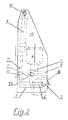
- Fig. 2 die gleiche Anordnung von der linken Seite aus gesehen.
- Die Verbindung besteht aus der mit einer U-förmigen Nut versehenen Aufnahme 1 und dem in diese ragenden Eingreifteil 2. Die Aufnahme 1 ist durch Schrauben 3 am Zylinder 4 bzw. an der Zylinderstange 4′ befestigt. Der Eingreifteil 2 ist am Türwagen 5 angeordnet. Der Türwagen 5 läuft auf den beiden Schienen 6, welche in den Führungen 7 verschieblich gelagert sind. Durch einen eigenen Zylinder 8 und Drehhebel 9 werden die Schienen 6 in der Führung 7 verschoben, wobei die Tür ein- bzw. ausschwenkt. Während des Schwenkvorganges gleiten der Eingreifteil 2 und die Aufnahme 1 ineinander, um den Schwenkweg zu kompensieren und die Krafteinleitung durch den Zylinder 4 zu ermöglichen. Die gesamte Anordnung ist vormontierbar in einem Gestell angeordnet.
- Dieses Gestell besteht aus den beiden Seitenteilen 10 und 10′ und dem Verbindungsholm 11, der zwischen den Seitenteilen 10, 10′ angeordnet ist. Die Führungen 7 für die Schienen 6 des Türwagens 5 sind in den Seitenteilen 10 und 10′ angeordnet. Für den Antrieb des Türwagens 5 ist der Zylinder 4 an einem der beiden Seitenteile 10 oder 10′ mittels Schrauben 12 befestigt. An jeder der beiden Seitenteile 10 und 10′ ist der Zylinder 8 für den Schwenkvorgang durch Verschraubungen 13 angebracht und mittels Versteller 14 justierbar. Er treibt den, ebenfalls jeweils im Seitenteil 10, 10′ gelagerten Drehhebel 9 an, mit dem er mittels Bolzenverbindung 15 verbunden ist. Die beiden Drehhebel 9, 9′ sind durch das Band 15 drehsteif miteinander verbunden. Dadurch ist sichergestellt, daß beide Drehhebel 9, 9′ gleichmäßig geschwenkt werden und kein Kanten oder Verklemmen in den Führungen 7 möglich ist. Die Hebel 9, 9′ sind mittels der Lagerungen 17 und Verschraubungen 18 befestigt.
- Die Erfindung ist nicht auf die dargestellte Ausführung beschränkt, sondern ist diese nur beispielhaft.
Claims (3)
Applications Claiming Priority (2)
| Application Number | Priority Date | Filing Date | Title |
|---|---|---|---|
| AT1695/88 | 1988-06-29 | ||
| AT169588A AT391911B (de) | 1988-06-29 | 1988-06-29 | Kraftuebertragungseinrichtung fuer schwenkschiebetueren an fahrzeugen |
Publications (3)
| Publication Number | Publication Date |
|---|---|
| EP0349525A2 true EP0349525A2 (de) | 1990-01-03 |
| EP0349525A3 EP0349525A3 (en) | 1990-03-28 |
| EP0349525B1 EP0349525B1 (de) | 1994-03-02 |
Family
ID=3518996
Family Applications (1)
| Application Number | Title | Priority Date | Filing Date |
|---|---|---|---|
| EP19890890176 Expired - Lifetime EP0349525B1 (de) | 1988-06-29 | 1989-06-27 | Kraftübertragung für Schwenkschiebetüren an Fahrzeugen |
Country Status (3)
| Country | Link |
|---|---|
| EP (1) | EP0349525B1 (de) |
| AT (1) | AT391911B (de) |
| DE (1) | DE58907065D1 (de) |
Family Cites Families (5)
| Publication number | Priority date | Publication date | Assignee | Title |
|---|---|---|---|---|
| DE854665C (de) * | 1943-01-09 | 1952-11-06 | Ver Baubeschlag Gretsch Co | Druckmittelantrieb fuer Schwenk-Schiebetueren, insbesondere fuer Fahrzeugtueren |
| US2746813A (en) * | 1951-11-16 | 1956-05-22 | Massa Frank | Means for reducing static friction |
| DE2657285A1 (de) * | 1975-12-20 | 1977-07-07 | Westinghouse Brake & Signal | Tuersteuervorrichtung mit einem schwingarm |
| AT361035B (de) * | 1978-12-04 | 1981-02-10 | Ife Gmbh | Antriebsvorrichtung fuer schiebetuerfluegel oder schwenkschiebetuerfluegel von fahrzeugtueren |
| JPS60155882U (ja) * | 1984-03-26 | 1985-10-17 | 木下 日雄 | 冷蔵庫の自動扉 |
-
1988
- 1988-06-29 AT AT169588A patent/AT391911B/de not_active IP Right Cessation
-
1989
- 1989-06-27 EP EP19890890176 patent/EP0349525B1/de not_active Expired - Lifetime
- 1989-06-27 DE DE89890176T patent/DE58907065D1/de not_active Expired - Fee Related
Also Published As
| Publication number | Publication date |
|---|---|
| ATA169588A (de) | 1990-06-15 |
| AT391911B (de) | 1990-12-27 |
| EP0349525B1 (de) | 1994-03-02 |
| EP0349525A3 (en) | 1990-03-28 |
| DE58907065D1 (de) | 1994-04-07 |
Similar Documents
| Publication | Publication Date | Title |
|---|---|---|
| DE3816175C2 (de) | ||
| EP0941889B1 (de) | Ausziehvorrichtung | |
| EP0523630A1 (de) | Antrieb für Sektionaltore | |
| DE3004082C2 (de) | Einrichtung zur Steuerung der Schwenkbewegung eines Radsatzes eines Schienenfahrzeuges in einer Kurve | |
| DE60219764T2 (de) | Kupplungspedal fur ein kraftfahrzeug | |
| WO2007107390A1 (de) | Beschlag für ein fenster oder eine tür | |
| DE3942016C2 (de) | ||
| DE2913742A1 (de) | Universalmanipulator fuer die wiederholungspruefung an reaktordruckbehaeltern | |
| DE2909945A1 (de) | Schieberverschluss fuer giesspfannen u.ae. | |
| EP0139046B1 (de) | Schiebetür- oder Schiebefensteranordnung | |
| EP0349525A2 (de) | Kraftübertragung für Schwenkschiebetüren an Fahrzeugen | |
| DE3620290A1 (de) | Linearantriebseinheit | |
| DE3933640C2 (de) | ||
| DE4427518C1 (de) | Fahrzeugaufbau, insbesondere für Lastkraftwagen und Anhänger, mit einer öffenbaren Seitenwand | |
| DE3317592C2 (de) | Bohrstangenführung für eine Bohrmaschine | |
| WO2010063586A1 (de) | Doppelantrieb für möbel | |
| DE4240725C1 (de) | Biegemaschine für Draht- oder Bandmaterial | |
| DE19745967C1 (de) | Tragvorrichtung für Kameras | |
| DE2508106B2 (de) | Vorrichtung zum öffnen und Schließen von Schiebedächern für Kraftfahrzeuge | |
| CH646376A5 (en) | Holding device with a drive for adjusting a turning bar | |
| EP0461104B1 (de) | Schwenkschiebetür | |
| DE60112854T2 (de) | Bewegungsübertragungssystem für teleskopische Flügel von Aufzugstüren | |
| DE1505966A1 (de) | Lokomotive fuer eine Einschienenhaengebahn Case D | |
| DE2540657C2 (de) | Antriebs- und Verriegelungsvorrichtung für ein zu verschiebendes Teil, beispielsweise für eine Schiebetür | |
| DE102005047297B3 (de) | Antriebsvorrichtung für einen Verdeckkastendeckel eines Kraftfahrzeugs |
Legal Events
| Date | Code | Title | Description |
|---|---|---|---|
| PUAI | Public reference made under article 153(3) epc to a published international application that has entered the european phase |
Free format text: ORIGINAL CODE: 0009012 |
|
| 17P | Request for examination filed |
Effective date: 19890705 |
|
| AK | Designated contracting states |
Kind code of ref document: A2 Designated state(s): BE DE FR GB IT |
|
| PUAL | Search report despatched |
Free format text: ORIGINAL CODE: 0009013 |
|
| AK | Designated contracting states |
Kind code of ref document: A3 Designated state(s): BE DE FR GB IT |
|
| RHK1 | Main classification (correction) |
Ipc: E05F 15/02 |
|
| 17Q | First examination report despatched |
Effective date: 19910726 |
|
| RAP1 | Party data changed (applicant data changed or rights of an application transferred) |
Owner name: WIENER METALLWERK GMBH |
|
| GRAA | (expected) grant |
Free format text: ORIGINAL CODE: 0009210 |
|
| AK | Designated contracting states |
Kind code of ref document: B1 Designated state(s): BE DE FR GB IT |
|
| ITF | It: translation for a ep patent filed | ||
| REF | Corresponds to: |
Ref document number: 58907065 Country of ref document: DE Date of ref document: 19940407 |
|
| GBT | Gb: translation of ep patent filed (gb section 77(6)(a)/1977) |
Effective date: 19940328 |
|
| PGFP | Annual fee paid to national office [announced via postgrant information from national office to epo] |
Ref country code: GB Payment date: 19940517 Year of fee payment: 6 |
|
| PGFP | Annual fee paid to national office [announced via postgrant information from national office to epo] |
Ref country code: BE Payment date: 19940524 Year of fee payment: 6 |
|
| ET | Fr: translation filed | ||
| PGFP | Annual fee paid to national office [announced via postgrant information from national office to epo] |
Ref country code: FR Payment date: 19940622 Year of fee payment: 6 |
|
| PGFP | Annual fee paid to national office [announced via postgrant information from national office to epo] |
Ref country code: DE Payment date: 19940630 Year of fee payment: 6 |
|
| PLBE | No opposition filed within time limit |
Free format text: ORIGINAL CODE: 0009261 |
|
| STAA | Information on the status of an ep patent application or granted ep patent |
Free format text: STATUS: NO OPPOSITION FILED WITHIN TIME LIMIT |
|
| 26N | No opposition filed | ||
| PG25 | Lapsed in a contracting state [announced via postgrant information from national office to epo] |
Ref country code: GB Effective date: 19950627 |
|
| PG25 | Lapsed in a contracting state [announced via postgrant information from national office to epo] |
Ref country code: BE Effective date: 19950630 |
|
| BERE | Be: lapsed |
Owner name: WIENER METALLWERK G.M.B.H. Effective date: 19950630 |
|
| GBPC | Gb: european patent ceased through non-payment of renewal fee |
Effective date: 19950627 |
|
| PG25 | Lapsed in a contracting state [announced via postgrant information from national office to epo] |
Ref country code: FR Effective date: 19960229 |
|
| PG25 | Lapsed in a contracting state [announced via postgrant information from national office to epo] |
Ref country code: DE Effective date: 19960301 |
|
| REG | Reference to a national code |
Ref country code: FR Ref legal event code: ST |
|
| PG25 | Lapsed in a contracting state [announced via postgrant information from national office to epo] |
Ref country code: IT Free format text: LAPSE BECAUSE OF NON-PAYMENT OF DUE FEES;WARNING: LAPSES OF ITALIAN PATENTS WITH EFFECTIVE DATE BEFORE 2007 MAY HAVE OCCURRED AT ANY TIME BEFORE 2007. THE CORRECT EFFECTIVE DATE MAY BE DIFFERENT FROM THE ONE RECORDED. Effective date: 20050627 |