EP0349525B1 - Kraftübertragung für Schwenkschiebetüren an Fahrzeugen - Google Patents
Kraftübertragung für Schwenkschiebetüren an Fahrzeugen Download PDFInfo
- Publication number
- EP0349525B1 EP0349525B1 EP19890890176 EP89890176A EP0349525B1 EP 0349525 B1 EP0349525 B1 EP 0349525B1 EP 19890890176 EP19890890176 EP 19890890176 EP 89890176 A EP89890176 A EP 89890176A EP 0349525 B1 EP0349525 B1 EP 0349525B1
- Authority
- EP
- European Patent Office
- Prior art keywords
- door
- cylinder
- vehicles
- swinging
- piston drive
- Prior art date
- Legal status (The legal status is an assumption and is not a legal conclusion. Google has not performed a legal analysis and makes no representation as to the accuracy of the status listed.)
- Expired - Lifetime
Links
- 230000005540 biological transmission Effects 0.000 title 1
- 238000010276 construction Methods 0.000 description 3
- 238000000034 method Methods 0.000 description 3
- 238000001816 cooling Methods 0.000 description 1
- 230000002028 premature Effects 0.000 description 1
- 230000008439 repair process Effects 0.000 description 1
Images
Classifications
-
- E—FIXED CONSTRUCTIONS
- E05—LOCKS; KEYS; WINDOW OR DOOR FITTINGS; SAFES
- E05F—DEVICES FOR MOVING WINGS INTO OPEN OR CLOSED POSITION; CHECKS FOR WINGS; WING FITTINGS NOT OTHERWISE PROVIDED FOR, CONCERNED WITH THE FUNCTIONING OF THE WING
- E05F15/00—Power-operated mechanisms for wings
- E05F15/50—Power-operated mechanisms for wings using fluid-pressure actuators
- E05F15/56—Power-operated mechanisms for wings using fluid-pressure actuators for horizontally-sliding wings
- E05F15/565—Power-operated mechanisms for wings using fluid-pressure actuators for horizontally-sliding wings for railway-cars
-
- E—FIXED CONSTRUCTIONS
- E05—LOCKS; KEYS; WINDOW OR DOOR FITTINGS; SAFES
- E05Y—INDEXING SCHEME ASSOCIATED WITH SUBCLASSES E05D AND E05F, RELATING TO CONSTRUCTION ELEMENTS, ELECTRIC CONTROL, POWER SUPPLY, POWER SIGNAL OR TRANSMISSION, USER INTERFACES, MOUNTING OR COUPLING, DETAILS, ACCESSORIES, AUXILIARY OPERATIONS NOT OTHERWISE PROVIDED FOR, APPLICATION THEREOF
- E05Y2900/00—Application of doors, windows, wings or fittings thereof
- E05Y2900/50—Application of doors, windows, wings or fittings thereof for vehicles
- E05Y2900/51—Application of doors, windows, wings or fittings thereof for vehicles for railway cars or mass transit vehicles
Definitions
- the invention relates to a pivoting sliding door for vehicles.
- a door for stationary cooling units is known from US Pat. No. 4,688,352.
- This door has a slide pin, along which a slide bearing can be moved.
- This plain bearing in turn carries rollers that are guided in a rail along which the door can be moved. If the door is in the closed position, the door can be moved along the sliding pins into the closed position using suitable units.
- the present invention is based on a prior art, as given by DE-C-854 665.
- a pivoting sliding door is described, the door being moved out of the door wall in its closed position via a cam, and then being able to be moved from this closed position into the open position by means of a piston / cylinder unit.
- the device with which the pivoting movement of the door is carried out in detail can not be found in this patent.
- a cylinder In known drives for pivoting sliding doors, a cylinder is generally provided which engages with one end on the door box and with the other on a door leaf or door trolley. Such a cylinder is pivotable stored to allow the change of the angle between the door leaf and cylinder during the opening and closing process.
- Such a kinematic sequence leads to higher force loads at the points where force is applied, particularly in the door. The forces required to open or close the door are disproportionately high because large masses have to be moved.
- it must also be taken into account that flexible connections for supplying the cylinder with pressure medium are required which, on the one hand, require more effort during assembly and, on the other hand, give rise to premature faults and thus repairs.
- the present invention has set itself the goal of avoiding the disadvantages mentioned above.
- a door is provided with a door carriage, which can be moved along a rail via a first cylinder / piston drive from a closed position to an open position and vice versa, the door carriage being movable transversely to the opening direction in the closed position essential in that the rail can be moved together with the door carriage via a further cylinder / piston drive along a guide transversely to the opening direction, the first cylinder / piston drive being fixed immovably on the door frame and the movable part, in particular the cylinder rod, of which has a receptacle for an engagement part , which can be moved together with the door trolley and which slide into one another when moving transversely to the opening direction.
- the cylinder / piston drive can be arranged fixed on the door box, so that neither joints nor flexible connections are required for a pressure medium.
- the cylinder can be parallel to the door leaf guide, the changing distance between the door box and door leaf being taken into account particularly simply by the parts sliding into one another when the door is being pushed out.
- the engaging part has a longitudinal extent which is at least the sum of the push-out path of the door leaf and the length of the groove in the receptacle, a construction with particularly high strength can be achieved.
- a kinematically particularly advantageous construction is provided when the rail can be displaced in the guide by means of a rotary lever to which the further cylinder / piston drive is articulated.
- the connection consists of the receptacle 1 provided with a U-shaped groove and the engaging part 2 projecting into it.
- the receptacle 1 is fastened by screws 3 to the cylinder 4 or to the cylinder rod 4 '.
- the engaging part 2 is arranged on the door carriage 5.
- the door carriage 5 runs on the two rails 6, which are slidably mounted in the guides 7.
- the rails 6 are displaced in the guide 7 by means of their own cylinder 8 and rotary lever 9, the door swiveling in and out.
- the engaging part 2 and the receptacle 1 slide into one another in order to compensate for the swiveling path and to enable the force to be introduced through the cylinder 4.
- the entire arrangement can be preassembled in a frame.
- This frame consists of the two side parts 10 and 10 'and the connecting bar 11, which is arranged between the side parts 10, 10'.
- the guides 7 for the rails 6 of the door carriage 5 are arranged in the side parts 10 and 10 '.
- the cylinder 4 is attached to one of the two side parts 10 or 10 'by means of screws 12.
- the cylinder 8 is attached for the pivoting process by screw 13 and adjustable by means of adjuster 14. He drives the, also in the side part 10, 10 'mounted rotary lever 9, to which it is connected by means of a bolt connection 15.
- the invention is not limited to the embodiment shown, but is only an example.
Landscapes
- Power-Operated Mechanisms For Wings (AREA)
- Automobile Manufacture Line, Endless Track Vehicle, Trailer (AREA)
Description
- Die Erfindung bezieht sich auf eine Schwenkschiebetüre für Fahrzeuge.
- Es sind unterschiedliche Konstruktionen von Türen bekannt. So wird beispielsweise aus der US-A-4 688 352 eine Türe für stationäre Kühleinheiten bekannt. Diese Türe weist einen Gleitstift auf, entlang welchem ein Gleitlager verschiebbar ist. Dieses Gleitlager trägt seinerseits Rollen, die in einer Schiene geführt sind, entlang welcher die Türe verschiebbar ist. Befindet sich die Türe in der Schließstellung, so kann über geeignete Aggregate die Türe entlang der Gleitstifte in die Geschlossenstellung bewegt werden.
- Die vorliegende Erfindung geht von einem Stand der Technik aus, wie er durch die DE-C-854 665 gegeben ist. In dieser Patentschrift wird eine Schwenkschiebetüre beschrieben, wobei die Türe in ihrer Schließstellung über eine Nocke aus der Türwandung herausbewegt wird, und sodann von dieser Schließstellung über ein Kolben/Zylinderaggregat in die Offenstellung bewegt werden kann. Die Vorrichtung, mit welcher die Schwenkbewegung der Türe im einzelnen durchgeführt wird, kann dieser Patentschrift nicht entnommen werden.
- Bei bekannten Antrieben für Schwenkschiebetüren ist in der Regel ein Zylinder vorgesehen, welcher mit einem Ende am Türkasten und mit dem anderen an einem Türblatt oder Türwagen angreift. Ein derartiger Zylinder ist schwenkbar gelagert, um die Anderung des Winkels zwischen Türblatt und Zylinder während des Öffnungs- und Schließvorganges zu ermöglichen. Durch einen derartigen kinematischen Ablauf kommt es zu höheren Kraftbeanspruchungen an den Stellen der Krafteinleitung, insbesondere in die Türe. Die erforderlichen Kräfte, um die Türe zu öffnen bzw. zu schließen, sind unverhältnismäßig hoch, da große Massen zu bewegen sind. Neben diesem Nachteil ist auch noch zu berücksichtigen, daß flexible Verbindungen zur Versorgung des Zylinders mit Druckmedium erforderlich sind, die einerseits höheren Aufwand bei der Montage bedingen und anderseits Anlaß zu vorzeitigen Störungen und damit Reparaturen bieten.
- Die vorliegende Erfindung hat sich zum Ziel gesetzt, die oben angeführten Nachteile zu vermeiden.
- Die erfindungsgemäße Schwenkschiebetüre für Fahrzeuge, wobei eine Türe mit einem Türwagen versehen ist, welcher entlang einer Schiene über einen ersten Zylinder/Kolbenantrieb von einer Schließstellung in eine Offenstellung und umgekehrt bewegbar ist, wobei der Türwagen in der Schließstellung quer zur Öffnungsrichtung bewegbar ist, besteht im wesentlichen darin, daß die Schiene gemeinsam mit dem Türwagen über einen weiteren Zylinder/Kolbenantrieb entlang einer Führung quer zur Öffnungsrichtung bewegbar ist, wobei der erste Zylinder/Kolbenantrieb am Türrahmen unverschieblich befestigt ist und dessen beweglicher Teil, insbesondere die Zylinderstange eine Aufnahme für einen Eingreifteil aufweist, der gemeinsam mit dem Türwagen bewegbar ist und die bei der Bewegung quer zur Öffnungsrichtung ineinandergleiten.
- Bei einer derartigen konstruktiven Ausbildung kann der Zylinder/Kolbenantrieb fest am Türkasten angeordnet sein, womit weder Gelenke noch flexible Verbindungen für ein Druckmedium erforderlich sind. Der Zylinder kann parallel zur Türblattführung stehen, wobei während des Ausschiebens der Türe den sich ändernden Abstand zwischen Türkasten und Türblatt durch die ineinandergleitenden Teile besonders einfach Rechnung getragen wird.
- Eine weitere konstruktiv besonders einfache Ausbildung ist dann gegeben, wenn die Aufnahme eine U-förmige Nut aufweist und der Eingreifteil in diese ragt.
- Besitzt der Eingreifteil eine Längserstreckung, welche zumindest die Summe des Ausschiebeweges des Türblattes und der Länge der Nut in der Aufnahme beträgt, so kann eine konstruktive Ausbildung mit besonders hoher Festigkeit erreicht werden.
- Eine kinematisch besonders vorteilhafte Konstruktion ist dann gegeben, wenn die Schiene über Drehhebel, an welchem der weitere Zylinder/Kolbenantrieb angelenkt ist, in der Fuhrung verschiebbar ist.
- Im folgenden wird die Erfindung anhand der Zeichnungen näher erläutert.
- Es zeigen:
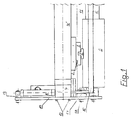
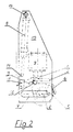
- Fig. 1 den Antriebsteil einer Schwenkschiebetüre vom Wageninneren gesehen und
- Fig. 2 den Antrieb gemäß Fig. 1 in Seitenansicht.
- Die Verbindung besteht aus der mit einer U-förmigen Nut versehenen Aufnahme 1 und dem in diese ragenden Eingreifteil 2. Die Aufnahme 1 ist durch Schrauben 3 am Zylinder 4 bzw. an der Zylinderstange 4′ befestigt. Der Eingreifteil 2 ist am Türwagen 5 angeordnet. Der Türwagen 5 läuft auf den beiden Schienen 6, welche in den Führungen 7 verschieblich gelagert sind. Durch einen eigenen Zylinder 8 und Drehhebel 9 werden die Schienen 6 in der Führung 7 verschoben, wobei die Tür ein- bzw. ausschwenkt. Während des Schwenkvorganges gleiten der Eingreifteil 2 und die Aufnahme 1 ineinander, um den Schwenkweg zu kompensieren und die Krafteinleitung durch den Zylinder 4 zu ermöglichen. Die gesamte Anordnung ist vormontierbar in einem Gestell angeordnet.
- Dieses Gestell besteht aus den beiden Seitenteilen 10 und 10′ und dem Verbindungsholm 11, der zwischen den Seitenteilen 10, 10′ angeordnet ist. Die Führungen 7 für die Schienen 6 des Türwagens 5 sind in den Seitenteilen 10 und 10′ angeordnet. Für den Antrieb des Türwagens 5 ist der Zylinder 4 an einem der beiden Seitenteile 10 oder 10′ mittels Schrauben 12 befestigt. An jeder der beiden Seitenteile 10 und 10′ ist der Zylinder 8 für den Schwenkvorgang durch Verschraubungen 13 angebracht und mittels Versteller 14 justierbar. Er treibt den, ebenfalls jeweils im Seitenteil 10, 10′ gelagerten Drehhebel 9 an, mit dem er mittels Bolzenverbindung 15 verbunden ist. Die beiden Drehhebel 9, 9′ sind durch das Band 15 drehsteif miteinander verbunden. Dadurch ist sichergestellt, daß beide Drehhebel 9, 9′ gleichmäßig geschwenkt werden und kein Kanten oder Verklemmen in den Führungen 7 möglich ist. Die Hebel 9, 9′ sind mittels der Lagerungen 17 und Verschraubungen 18 befestigt.
- Die Erfindung ist nicht auf die dargestellte Ausführung beschränkt, sondern ist diese nur beispielhaft.
Claims (4)
- Schwenkschiebetüre für Fahrzeuge, wobei eine Türe mit einem Türwagen (5) versehen ist, welcher entlang einer Schiene (6) über einen ersten Zylinder/Kolbenantrieb (4) von einer Schließstellung in eine Offenstellung und umgekehrt bewegbar ist, wobei der Türwagen (5) in der Schließstellung quer zur Öffnungsrichtung bewegbar ist, dadurch gekennzeichnet, daß die Schiene (6) gemeinsam mit dem Türwagen (5) über einen weiteren Zylinder/Kolbenantrieb (8) entlang einer Führung (7) quer zur Öffnungsrichtung bewegbar ist, wobei der erste Zylinder/Kolbenantrieb (4) am Türrahmen unverschieblich befestigt ist und dessen beweglicher Teil, insbesondere die Zylinderstange (4') eine Aufnahme (1) für einen Eingreifteil (2) aufweist, der gemeinsam mit dem Türwagen bewegbar ist und die bei der Bewegung quer zur Öffnungsrichtung ineinander gleiten.
- Schwenkschiebetüre für Fahrzeuge nach Anspruch 1, dadurch gekennzeichnet, daß die Aufnahme (1) eine U-förmige Nut aufweist und der Eingreifteil (2) in diese ragt.
- Schwenkschiebetüre für Fahrzeuge nach Anspruch 1 oder 2, dadurch gekennzeichnet, daß der Eingreifteil (2) eine Längserstreckung besitzt, die zumindest die Summe des Ausschiebeweges des Türblattes und der Lange der Nut in der Aufnahme (1) beträgt.
- Schwenkschiebetüre für Fahrzeuge nach einem der Ansprüche 1, 2 oder 3, dadurch gekennzeichnet, daß die Schiene (6) über Drehhebel (9), an welchem der weitere Zylinder/Kolbenantrieb (8) angelenkt ist, in der Führung (7) verschiebbar ist.
Applications Claiming Priority (2)
| Application Number | Priority Date | Filing Date | Title |
|---|---|---|---|
| AT1695/88 | 1988-06-29 | ||
| AT169588A AT391911B (de) | 1988-06-29 | 1988-06-29 | Kraftuebertragungseinrichtung fuer schwenkschiebetueren an fahrzeugen |
Publications (3)
| Publication Number | Publication Date |
|---|---|
| EP0349525A2 EP0349525A2 (de) | 1990-01-03 |
| EP0349525A3 EP0349525A3 (en) | 1990-03-28 |
| EP0349525B1 true EP0349525B1 (de) | 1994-03-02 |
Family
ID=3518996
Family Applications (1)
| Application Number | Title | Priority Date | Filing Date |
|---|---|---|---|
| EP19890890176 Expired - Lifetime EP0349525B1 (de) | 1988-06-29 | 1989-06-27 | Kraftübertragung für Schwenkschiebetüren an Fahrzeugen |
Country Status (3)
| Country | Link |
|---|---|
| EP (1) | EP0349525B1 (de) |
| AT (1) | AT391911B (de) |
| DE (1) | DE58907065D1 (de) |
Family Cites Families (5)
| Publication number | Priority date | Publication date | Assignee | Title |
|---|---|---|---|---|
| DE854665C (de) * | 1943-01-09 | 1952-11-06 | Ver Baubeschlag Gretsch Co | Druckmittelantrieb fuer Schwenk-Schiebetueren, insbesondere fuer Fahrzeugtueren |
| US2746813A (en) * | 1951-11-16 | 1956-05-22 | Massa Frank | Means for reducing static friction |
| DE2657285A1 (de) * | 1975-12-20 | 1977-07-07 | Westinghouse Brake & Signal | Tuersteuervorrichtung mit einem schwingarm |
| AT361035B (de) * | 1978-12-04 | 1981-02-10 | Ife Gmbh | Antriebsvorrichtung fuer schiebetuerfluegel oder schwenkschiebetuerfluegel von fahrzeugtueren |
| JPS60155882U (ja) * | 1984-03-26 | 1985-10-17 | 木下 日雄 | 冷蔵庫の自動扉 |
-
1988
- 1988-06-29 AT AT169588A patent/AT391911B/de not_active IP Right Cessation
-
1989
- 1989-06-27 EP EP19890890176 patent/EP0349525B1/de not_active Expired - Lifetime
- 1989-06-27 DE DE89890176T patent/DE58907065D1/de not_active Expired - Fee Related
Also Published As
| Publication number | Publication date |
|---|---|
| EP0349525A2 (de) | 1990-01-03 |
| ATA169588A (de) | 1990-06-15 |
| AT391911B (de) | 1990-12-27 |
| EP0349525A3 (en) | 1990-03-28 |
| DE58907065D1 (de) | 1994-04-07 |
Similar Documents
| Publication | Publication Date | Title |
|---|---|---|
| DE2554873C3 (de) | Tür mit Lavierbewegung | |
| DE69216232T2 (de) | Einrichtung für Schwenkschiebetüren für Eisenbahn- und Strassenbahnfahrzeuge | |
| DE102020209607B4 (de) | Verschlussanordnung zum Verschließen einer Tankmulde einer Karosserie eines Kraftfahrzeugs | |
| DE4201289C2 (de) | Vorrichtung zur Handhabung von Werkstücken | |
| EP0941889B1 (de) | Ausziehvorrichtung | |
| DE3004082C2 (de) | Einrichtung zur Steuerung der Schwenkbewegung eines Radsatzes eines Schienenfahrzeuges in einer Kurve | |
| EP0716004A1 (de) | Schwenkschiebetür für Fahrzeuge zur Personenbeförderung | |
| DE1580603C3 (de) | Bedienungs und Vernegelungsvor richtung fur ein Fahrzeugschiebedach | |
| DE19946501A1 (de) | Schwenkschiebetür | |
| DE102007050353A1 (de) | Greifvorrichtung | |
| DE19535578B4 (de) | Weichenantrieb mit Innenverschluß | |
| EP0349525B1 (de) | Kraftübertragung für Schwenkschiebetüren an Fahrzeugen | |
| AT395199B (de) | Schwenkschiebetuer, insbesondere fuer fahrzeuge | |
| DE2427334A1 (de) | Schwenkschiebetuer | |
| DE2653680C2 (de) | ||
| DE19745967C1 (de) | Tragvorrichtung für Kameras | |
| DE102005047297B3 (de) | Antriebsvorrichtung für einen Verdeckkastendeckel eines Kraftfahrzeugs | |
| DE2540657C2 (de) | Antriebs- und Verriegelungsvorrichtung für ein zu verschiebendes Teil, beispielsweise für eine Schiebetür | |
| DE2550207A1 (de) | Pneumatischer doppelantrieb fuer schwing- oder drehtueren | |
| EP0461104A1 (de) | Schwenkschiebetür | |
| EP0058827A2 (de) | Hebelwerkzeug | |
| EP4527713A1 (de) | Verfahren zum entkuppeln eines kupplungskopfs einer kupplung eines schienenfahrzeugs, sowie eine vorrichtung zur durchführung des verfahrens | |
| DE2918789C2 (de) | Fensterheber | |
| DE3245123A1 (de) | Verschlusskappe fuer oeffnungen in vertikalen waenden | |
| DE19701799A1 (de) | Ausstellmechanismus |
Legal Events
| Date | Code | Title | Description |
|---|---|---|---|
| PUAI | Public reference made under article 153(3) epc to a published international application that has entered the european phase |
Free format text: ORIGINAL CODE: 0009012 |
|
| 17P | Request for examination filed |
Effective date: 19890705 |
|
| AK | Designated contracting states |
Kind code of ref document: A2 Designated state(s): BE DE FR GB IT |
|
| PUAL | Search report despatched |
Free format text: ORIGINAL CODE: 0009013 |
|
| AK | Designated contracting states |
Kind code of ref document: A3 Designated state(s): BE DE FR GB IT |
|
| RHK1 | Main classification (correction) |
Ipc: E05F 15/02 |
|
| 17Q | First examination report despatched |
Effective date: 19910726 |
|
| RAP1 | Party data changed (applicant data changed or rights of an application transferred) |
Owner name: WIENER METALLWERK GMBH |
|
| GRAA | (expected) grant |
Free format text: ORIGINAL CODE: 0009210 |
|
| AK | Designated contracting states |
Kind code of ref document: B1 Designated state(s): BE DE FR GB IT |
|
| ITF | It: translation for a ep patent filed | ||
| REF | Corresponds to: |
Ref document number: 58907065 Country of ref document: DE Date of ref document: 19940407 |
|
| GBT | Gb: translation of ep patent filed (gb section 77(6)(a)/1977) |
Effective date: 19940328 |
|
| PGFP | Annual fee paid to national office [announced via postgrant information from national office to epo] |
Ref country code: GB Payment date: 19940517 Year of fee payment: 6 |
|
| PGFP | Annual fee paid to national office [announced via postgrant information from national office to epo] |
Ref country code: BE Payment date: 19940524 Year of fee payment: 6 |
|
| ET | Fr: translation filed | ||
| PGFP | Annual fee paid to national office [announced via postgrant information from national office to epo] |
Ref country code: FR Payment date: 19940622 Year of fee payment: 6 |
|
| PGFP | Annual fee paid to national office [announced via postgrant information from national office to epo] |
Ref country code: DE Payment date: 19940630 Year of fee payment: 6 |
|
| PLBE | No opposition filed within time limit |
Free format text: ORIGINAL CODE: 0009261 |
|
| STAA | Information on the status of an ep patent application or granted ep patent |
Free format text: STATUS: NO OPPOSITION FILED WITHIN TIME LIMIT |
|
| 26N | No opposition filed | ||
| PG25 | Lapsed in a contracting state [announced via postgrant information from national office to epo] |
Ref country code: GB Effective date: 19950627 |
|
| PG25 | Lapsed in a contracting state [announced via postgrant information from national office to epo] |
Ref country code: BE Effective date: 19950630 |
|
| BERE | Be: lapsed |
Owner name: WIENER METALLWERK G.M.B.H. Effective date: 19950630 |
|
| GBPC | Gb: european patent ceased through non-payment of renewal fee |
Effective date: 19950627 |
|
| PG25 | Lapsed in a contracting state [announced via postgrant information from national office to epo] |
Ref country code: FR Effective date: 19960229 |
|
| PG25 | Lapsed in a contracting state [announced via postgrant information from national office to epo] |
Ref country code: DE Effective date: 19960301 |
|
| REG | Reference to a national code |
Ref country code: FR Ref legal event code: ST |
|
| PG25 | Lapsed in a contracting state [announced via postgrant information from national office to epo] |
Ref country code: IT Free format text: LAPSE BECAUSE OF NON-PAYMENT OF DUE FEES;WARNING: LAPSES OF ITALIAN PATENTS WITH EFFECTIVE DATE BEFORE 2007 MAY HAVE OCCURRED AT ANY TIME BEFORE 2007. THE CORRECT EFFECTIVE DATE MAY BE DIFFERENT FROM THE ONE RECORDED. Effective date: 20050627 |