EP0348216B1 - Kassette für optische Platte - Google Patents
Kassette für optische Platte Download PDFInfo
- Publication number
- EP0348216B1 EP0348216B1 EP89306376A EP89306376A EP0348216B1 EP 0348216 B1 EP0348216 B1 EP 0348216B1 EP 89306376 A EP89306376 A EP 89306376A EP 89306376 A EP89306376 A EP 89306376A EP 0348216 B1 EP0348216 B1 EP 0348216B1
- Authority
- EP
- European Patent Office
- Prior art keywords
- opening
- shutter
- case
- optical disc
- side wall
- Prior art date
- Legal status (The legal status is an assumption and is not a legal conclusion. Google has not performed a legal analysis and makes no representation as to the accuracy of the status listed.)
- Expired - Lifetime
Links
Images


Classifications
-
- G—PHYSICS
- G11—INFORMATION STORAGE
- G11B—INFORMATION STORAGE BASED ON RELATIVE MOVEMENT BETWEEN RECORD CARRIER AND TRANSDUCER
- G11B23/00—Record carriers not specific to the method of recording or reproducing; Accessories, e.g. containers, specially adapted for co-operation with the recording or reproducing apparatus ; Intermediate mediums; Apparatus or processes specially adapted for their manufacture
- G11B23/02—Containers; Storing means both adapted to cooperate with the recording or reproducing means
- G11B23/03—Containers for flat record carriers
- G11B23/0301—Details
- G11B23/0308—Shutters
-
- G—PHYSICS
- G11—INFORMATION STORAGE
- G11B—INFORMATION STORAGE BASED ON RELATIVE MOVEMENT BETWEEN RECORD CARRIER AND TRANSDUCER
- G11B11/00—Recording on or reproducing from the same record carrier wherein for these two operations the methods are covered by different main groups of groups G11B3/00 - G11B7/00 or by different subgroups of group G11B9/00; Record carriers therefor
- G11B11/10—Recording on or reproducing from the same record carrier wherein for these two operations the methods are covered by different main groups of groups G11B3/00 - G11B7/00 or by different subgroups of group G11B9/00; Record carriers therefor using recording by magnetic means or other means for magnetisation or demagnetisation of a record carrier, e.g. light induced spin magnetisation; Demagnetisation by thermal or stress means in the presence or not of an orienting magnetic field
- G11B11/105—Recording on or reproducing from the same record carrier wherein for these two operations the methods are covered by different main groups of groups G11B3/00 - G11B7/00 or by different subgroups of group G11B9/00; Record carriers therefor using recording by magnetic means or other means for magnetisation or demagnetisation of a record carrier, e.g. light induced spin magnetisation; Demagnetisation by thermal or stress means in the presence or not of an orienting magnetic field using a beam of light or a magnetic field for recording by change of magnetisation and a beam of light for reproducing, i.e. magneto-optical, e.g. light-induced thermomagnetic recording, spin magnetisation recording, Kerr or Faraday effect reproducing
- G11B11/1055—Disposition or mounting of transducers relative to record carriers
- G11B11/10556—Disposition or mounting of transducers relative to record carriers with provision for moving or switching or masking the transducers in or out of their operative position
- G11B11/10558—Disposition or mounting of transducers relative to record carriers with provision for moving or switching or masking the transducers in or out of their operative position in view of the loading or unloading of the carrier
-
- G—PHYSICS
- G11—INFORMATION STORAGE
- G11B—INFORMATION STORAGE BASED ON RELATIVE MOVEMENT BETWEEN RECORD CARRIER AND TRANSDUCER
- G11B23/00—Record carriers not specific to the method of recording or reproducing; Accessories, e.g. containers, specially adapted for co-operation with the recording or reproducing apparatus ; Intermediate mediums; Apparatus or processes specially adapted for their manufacture
- G11B23/50—Reconditioning of record carriers; Cleaning of record carriers ; Carrying-off electrostatic charges
- G11B23/505—Reconditioning of record carriers; Cleaning of record carriers ; Carrying-off electrostatic charges of disk carriers
- G11B23/507—Reconditioning of record carriers; Cleaning of record carriers ; Carrying-off electrostatic charges of disk carriers combined with means for reducing influence of physical parameters, e.g. temperature change, moisture
Definitions
- the present invention relates to an optical disc cartridge.
- Fig. 1 of the accompanying drawings is a perspective view showing a construction of a known optical disc cartridge and Fig. 2 is a sectional view thereof on line II-II of Fig. 1.
- This cartridge is considered to represent the closest prior art.
- reference numeral 1 indicates a plastics case of an optical disc cartridge in which a magneto optical disc 3 is housed.
- the case 1 is shaped like a flat board being hollow inside and having a thickness of several millimeters.
- the case 1 comprises two flat members, that is, an upper case 15 and lower case 16.
- the lower case 16 has a first opening 4 comprising a rectangular hole 6 and a centre hole 8.
- This first opening 4 is provided for access of an optical head (not shown), and the width and length thereof are those sufficient to allow the optical head access to the magneto optical disc 3.
- the upper case 15 has a second opening 5 of the same shape as that of the first opening 4.
- the second opening 5 is for a magnetic head 10 to access, and the width and length thereof are those sufficient to allow the magnetic head 10 set up on an arm 9 shown in Fig. 2 to access the magneto optical disc 3.
- the upper case 15 has thickness of l1.
- the shutter 2 is installed so that it moves freely between a position for closing both openings 4 and 5 and a position for opening them. It is usually energized at the position for closing by means of a spring 11 (refer to Fig. 3).
- the shutter 2 has an aperture 7, facing the first opening 4 of the case 1 when the shutter 2 is at the position for opening, and having the same shape as the first opening, the magnetic head 10 accessing the magneto optical disc 3 therefrom.
- Fig. 3 is a plan view of the upper case 15 side of the optical disc cartridge, when the shutter 2 is at the closing position.
- reference numeral 11 is a spring which changes its shape by the movement of the shutter 2, and energizes the shutter 2 at the position closing the opening 5.
- Fig. 4 shows a plan view of the lower case 16 side of the case 1.
- Fig. 4 shows the side for an optical head.
- numeral 6 indicates a rectangular aperture used when an optical head (not shown) is inserted
- 8 indicates a circle aperture joining with the rectangular aperture, used for inserting a mount for fitting a magneto optical disc when the magneto optical disc is driven by a motor (not shown). These two apertures form the first opening 4.
- Fig. 5(a) is an enlarged view of portion E in Fig. 4, and Fig 5(b) is a plan view, taking Fig. 5(a) to be a front view and Fig. 5(c) is a sectional view on line K-K in Fig. 5(b).
- numeral 25 indicates an outside board of the lower case 16, and since a notch 16b is formed at an end side of the aperture 6 of the first opening 4, the outside board 25 is thinner by a predetermined length than the other part 24 of the lower case 16. This leads an optical head to smooth accessing.
- Fig. 6(a) is a plan view showing a known shutter
- Fig. 6(b) is a left side view of the above
- Fig. 6(c) is a sectional view of the above on line M-M line in Fig. 6(a).
- the under face 33 of the lower case 16 side of the shutter 2 is narrower in width in comparison with the top face 34 of the upper case 15 side.
- An aperture 7 of approximately the same shape as the second opening 5 of the upper case is provided at the top face 34.
- a notch 18 is provided at the under face side of connecting portion 27 of the top face 34 with the under face 33.
- the notch 18 has a width which is the same as that of the aperture 7 and a depth corresponding to the notch 16b of the outside board 25 of the lower case 16.
- EP-A-0133734 discloses a hard disc cartridge arrangement comprising a housing and a "door arrangement" which allows the heads of the disc drive to enter the cartridge from its upper and lower surfaces. In the open position, an aperture in the door arrangement coincides with one which extends through three side walls of the housing to reveal both sides of the disc.
- US-A-4445157 discloses a flexible magnetic disc cassette, the cover of which containing the disc having pad and head insertion openings respectively on its opposite sides.
- the shutter has openings on the opposed plate portions thereof which are substantially the same shape as the pad and head openings, neither of which extend to the side edge of the cover.
- a guide groove is provided on the case along which the shutter slides.
- US-A-4,680,662 discloses another flexible magnetic disc having a guide groove in the side edge of the cover.
- a magnetic head is used for generating biased magnetic field for overwriting.
- the slider-type magnetic head 10 impresses magnetic field in the state that it rises from several »m to ten plus »m above a recording medium by means of dynamic pressure.
- An object of the present invention is to provide an optical disc cartridge which can do without an elevating mechanism for the magnetic head.
- Another object of the present invention is to provide an optical disc cartridge which controls the movement of a shutter and whose connecting part is strengthened.
- An object of an embodiment of the present invention is to provide an optical disc cartridge which supplies clean air all over the surface of a magneto optical disc facing a magnetic head.
- an optical disc cartridge comprising: a case containing a magneto-optical disc, which case has first and second opposing side walls, said first side wall having an opening for a magnetic head, and said second side wall having an opening for an optical head, a recessed portion which extends from said opening in said second side wall through an end wall of the case located between said first and second side walls, and a guide groove in said second side wall adjacent to and parallel with said end wall; and a substantially U-shaped shutter under which a portion of said first and second side walls and said end wall is located, which shutter is spring biased towards and movable from a position for closing to a position for opening said openings, said shutter has openings which correspond to the opening in said case defined by said opening in said first side wall and said recessed portion in said second side wall and said end wall when said shutter is in said position for opening, and has a projection which extends into said guide groove and is movable therein; characterised in that: said first side wall has a recessed portion which extends from
- An embodiment of the present invention provides an optical disc cartridge which supplies clean air all over the surface of a magneto optical disc facing a magnetic head by providing an air intake with a filter at the surface of an optical disc cartridge facing the magnetic head.
- Fig. 7 is a perspective view showing a construction of an embodiment of an optical disc cartridge of the present invention.
- Fig. 8 is a sectional view of this optical disc cartridge on line VIII-VIII in Fig. 7.
- reference numeral 1 indicates a plastics case of optical disc cartridge wherein a magneto optical disc 3 is housed.
- the case 1 is shaped like a flat board being hollow inside and having a thickness of several millimeters, comprising two flat members, that is, an upper case 15 and lower case 16.
- the lower case 16 has a first opening 4 comprising a rectangular hole 6 and a centre hole 8.
- the first opening 4 is for access of an optical head (11), and the width and length thereof are sufficient for the optical head to access a magneto optical disc 3.
- the upper case 15 has a second opening 5 for a magnetic head 10.
- the second opening 5 joins with a notch 15b which is a cut-off portion of an end surface 15a of the upper case 15, having a length which is enough for a magnetic head 10 to access the innermost track of the magneto optical disc 3.
- the width of the opening 5 is determined so that the slider-type magnetic head 10 which is set up on an arm 9 as shown in Fig. 8, can access all the track of the magneto optical disc, at the position where the magnetic head 10 faces an optical head 11. Thickness l2 of the case in the figure is thinner than that l1 of the conventional case by the length cut off.
- Reference numeral 2 indicates a shutter
- 17 indicates a notch at the upper case 15 side of the shutter 2
- 27 shows a bridge at the one end surface side of the case.
- the shutter 2 which is of stainless steel thin board, closes both the openings of the case 1 when an optical disc cartridge is taken out of the disc driving unit. This is located at one end of the case 1 so that having a U-shaped section it has both faces of the case therebetween.
- the shutter 2 is installed so that it moves freely between a position for closing both openings 4 and 5 and a position for opening them. It is usually energized to the position for closing be means of a spring (not shown).
- an aperture 7 therein faces the second opening 5 of the case 1, being wider in width and joining with a notch 17 engaging a notch 15b of the upper case 15.
- a notch 18 is also provided which faces a notch 16b of the lower case 16.
- Fig. 9 is a plan view of the lower case 16 side of the case 1.
- Fig. 9 shows the side at which an optical head 11 is located.
- reference numeral 6 indicates a rectangular aperture used when an optical head 11 is inserted
- 8 indicates a circle aperture which joins with the rectangular aperture, used for inserting a mount for fitting a magneto optical disc when the magneto optical disc is driven by a motor (not shown).
- These two apertures form the first opening 4.
- Fig. 10(a) is an enlarged view of a portion C indicated in Fig. 9
- Fig. 10(b) is a plan view where the view of Fig. 10(a) is taken to be a front view
- Fig. 10(c) is a sectional view on line G-G in Fig. 10(b).
- reference numeral 25 indicates an outside board of the lower case 16. Since a notch 16b is provided at an end side of the aperture 6 of the first opening 4, the outside board is thinner, by a predetermined length, than the other part 24 of the lower case 16. This leads an optical head to smooth accessing.
- a notch 15b which joins with the second opening 5. The width of the notch 15b is a little larger than the largest width of the magnetic head 10. Thus, it is not necessary for the magnetic head 10 to rise and fall to get over the end portion 15a of the upper case 15.
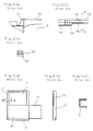
- Fig. 11 and Fig. 12 are plan views showing the construction of a shutter.
- Fig. 11(a) is a plan view of the shutter viewed from the lower case side
- Fig. 11(b) is a sectional view of the shutter on line A-A in Fig. 11(a).
- Fig. 12(a) is a plan view of the shutter viewed from the upper case side
- Fig. 12(b) is a front view of the shutter
- Figs. 12(c) and 12(d) are sectional views of the shutter on lines F-F and D-D respectively in Fig. 12(a).
- An under face 33 at the lower case 16 side of the shutter 2 is narrower in width when compared with a top face 34 of the upper case 15 side.
- the top face 34 has an aperture 7 of approximately the same shape as the second opening 5 of the upper case 15.
- the under face side of a connecting portion 27 of the top face 34 with the under face 33 has a notch 18 having the same width as the aperture 7 and a depth corresponding to the notch 16b of the outside board 25 of the lower case 16.
- the under board 26 At the edge of the connecting portion 27 is the under board 26 which is bent into an L-shape and is to be engaged with the aforesaid groove 23.
- a notch 17 of approximately the same width as that of the notch 15b joining with the second opening 5.
- a guide claw 28 which is bent into an L-shape. The claw 28 engages with the guide groove 16a to guide the movement of the shutter 2.
- the shutter 2 When an optical disc cartridge of the above construction is set in a disc driving unit not shown, the shutter 2 is moved from a position for closing to a position for opening by means of driving means provided in the disc driving unit, and the aperture 7 of the shutter 2 and the second opening 5 of the upper case 15 coordinate with each other.
- the notch 15b and the notch 17 are at the end portion 15a of the upper case 15 and at for connecting portion 27 of the shutter 2, respectively, and the thickness of the end portion of the case 1 is thinner than the conventional one, the magnetic head 10 is arranged on the recording medium 3 without getting over the end surface of the case 1.
- Fig. 13(a) is a plan view showing a construction of a shutter of an optical disc cartridge
- Fig. 13(b) is a side view thereof
- Fig. 13(c) is a sectional view of the shutter on line H-H in Fig. 13(a).
- a bent under board 26 is not provided and notch 17 has the same width as that of aperture 7, thereby, simplifying manufacturing and reducing costs.
- the strength for bending is lower because the width of end face 27 is narrow and is not bent.
- the embodiment shown in Fig. 11 and Fig. 12 has few problems as regards strength since it has a section of L-shape and C-shape. It is also capable of having a function of positional control by moving the shutter 2 with making the under board 26 go along with the groove 23.
- Fig. 14 shows a further embodiment in which the width of opening is reduced corresponding to the size of the magnetic head. Since the thickness of the shutter is thin, being usually about 0.3 mm, the above method increases the strength.
- reference numeral 7 is an aperture.
- the present invention has advantages, for example, there is no need for an arm which carries a magnetic head to have a rise and fall function, the disc driving unit can be small in size and accessing time can be reduced, by forming an opening for access of the magnetic head by cutting off an end of a case. Simultaneously, a groove, formed at the case, has also an effect for positional control of the shutter movement.
- Fig. 15 is a perspective view showing the construction of an embodiment of an optical disc cartridge illustrating this further feature
- Fig. 16 is a sectional view of the optical disc cartridge on line XVI-XVI in Fig. 15.
- reference numeral 1 indicates a plastics case of an optical disc cartridge in which a magneto optical disc 3 is housed.
- the case is shaped like a flat board being hollow inside, and having a thickness of several millimeters, and has a rectangular first opening 4 comprising a centre hole 8 at one surface.
- the first opening 4 is for access of an optical head 11, and has a width and length sufficient to allow the optical head 11 access to the magneto optical disc 3.
- Fig. 17 is an enlarged plan view showing the shape of a second opening 5 when the shutter 2 is positioned at the opening.
- the second opening 5 for the magnetic head 10 At the other surface of the case 1 is the second opening 5 for the magnetic head 10 having a smaller width than that of the first opening 4.
- the second opening 5 joins with a notch 15b which is a cut off portion of an end surface of the case 1, having a length which is enough for a magnetic head 10 to access the innermost track of the magneto optical disc 3 in the vicinity of the centre position at said other surface.
- the width of the second opening 5 is determined so that the slider-type magnetic head 10 which is set up on an arm 9 as shown in Fig. 17, can access all the track of the magneto optical disc at the position in which the magnetic head 10 faces an optical head 11.
- the second opening 5 is formed asymetrically in width to the dimensional centre line L-L of the case 1, and the relationship between the distance m2 from an end portion of the upstream side of the magneto optical disc 3 in the rotational direction shown by an arrow "A" to the centre line L-L and the distance m1 from an end portion of downstream side to the centre line L-L is m1 ⁇ m2.
- the surface of the second opening 5 side of the case 1 has a round shaped air intake 30 formed with the rotational centre of the magneto optical disc 3 as the centre position, the air intake 30 being provided with a filter 31 having numerous pores of about 0.5 »m.
- a shutter 2 of stainless steel thin board which closes both the openings 4 and 5 of the case 1 when an optical disc cartridge is taken out of the disc driving unit, is located at one end 1a of the case 1 so that it, having a U-shaped section, has both faces of the case therebetween.
- the shutter 2 is installed so that it moves freely between a position for closing both openings 4 and 5 and a position for opening them. It is usually energized at a position for closing by means of a spring (not shown).
- the shutter 2 has an aperture 7 which coordinates with the second opening 5 of the case 1 when the shutter 2 is at the position for opening, has the same shape as the opening 5, and has a notch 17.
- Fig. 18 is a side sectional view showing the relationship between a magnetic head and a magneto optical disc.
- the magnetic head 10 comprises a slider portion 10a which rises by dynamic pressure caused by rotation of the magneto optical disc 3, and a head portion 10b which is approximately C-shaped, its upper end being fixed to the slider portion 10a, and its lower end being spaced by a predetermined gap 22 from the slider portion 10a.
- the spot position of the optical head 11 corresponds to the centre position of the gap 22.
- the relationship between the distance m1 and the distance m2 must be determined in proportion to the distance n1 from the centre position of the gap 22 to the end portion of the head portion 10b, and the distance n2 from the centre position of the gap 22 to the end portion of the slider portion 10a.
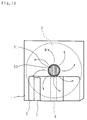
- Fig. 19 is a plan view of an optical disc cartridge, showing air flow taken into the case.
- the dust in the air taken in from the air intake 30 is removed by a filter 31, cleansed and then supplied on to the magneto optical disc 3.
- the air supplied proceeds from the centre to the periphery by means of the rotation of the magneto optical disc 3, and is diffused uniformly as shown by an arrow "B", forming stabilized air flow.
- the magnetic head 10 rises keeping the gap between the magneto optical disc 3 and itself constant.
- the shutter 2 is moved from the position for closing to the position for opening, and the notch 17 of the shutter 2 coordinates with the second opening 5 of the case 1.
- the magnetic head 10 is arranged on the magneto optical disc 3 without getting over the end surface of the case 1 since the notch 15b of the case is open.
- the air intake is circular in shape, and the centre position thereof is the rotational centre of the magneto optical disc, this invention is not limited to this arrangement.
- the air intake may not necessarily be circular in shape, and the centre position may not necessarily coincide with the rotational centre.
- the material of the shutter may not only be of stainless steel but also be of, for example, a synthetic resin.
Claims (3)
- Kassette für eine optische Platte, mit:
einem eine magneto-optische Platte (3) enthaltenden Gehäuse (1), das erste und zweite einander gegenüberliegende Seitenwände aufweist, wobei die erste Seitenwand (15) eine Öffnung (5) für einen magnetischen Kopf (10) und die zweite Seitenwand (16) eine Öffnung-für einen optischen Kopf (11) aufweist, einem ausgesparten Bereich (16b), der sich von der Öffnung (4) in der zweiten Seitenwand (16) durch eine Stirnwand des Gehäuses zwischen der ersten und der zweiten Seitenwand erstreckt, und einer Führungsnut (16a) in der zweiten Seitenwand (16), die an die Stirnwand angrenzt und parallel zu ihr verläuft, und
einem im wesentlichen U-förmigen Verschluß (2), unter dem ein Teil der ersten und der zweiten Seitenwand und die Stirnwand angeordnet sind, der in Richtung auf eine Position zum Schließen federnd vorgespannt und aus dieser heraus in eine Position zum Öffnen der Öffnungen (4,5) bewegbar ist, wobei der Verschluß (2) Öffnungen (7,18) aufweist, die mit den Öffnungen in dem Gehäuse korrespondieren, welche durch die Öffnung (5) in der ersten Seitenwand (15) und den ausgesparten Bereich (15b) in der zweiten Seitenwand (16) und der Stirnwand gebildet sind, wenn sich der Verschluß in der Position zum Öffnen befindet, und einen Vorsprung (28) aufweist, der in die Führungsnut (16a) hineinragt und darin bewegbar ist,
dadurch gekennzeichnet daß
die erste Seitenwand (15) einen ausgesparten Bereich (15b) aufweist, der sich von der Öffnung (5) in der ersten Seitenwand (15) durch die Stirnwand erstreckt, so daß die beiden ausgesparten Bereiche nicht durch die Stirnwand miteinander verbunden sind,
in der Stirnwand eine weitere Nut (23) vorgesehen ist, die sich von der Basis in der Stirnwand des ausgesparten Bereiches (16b) der zweiten Seitenwand erstreckt und mit dieser Basis bündig ist,
in dem Verschluß (2) eine weitere Öffnung (17) vorgesehen ist, die mit einer Öffnung in der Stirnwand des Gehäuses korrespondiert, die durch den ausgesparten Bereich (15b) in der ersten Seitenwand (15) gebildet wird, wenn der Verschluß (2) sich in der Position zum Öffnen befindet, und
der Verschluß einen weiteren-Vorsprung (26) aufweist, der von demjenigen Rand der Öffnung (18) absteht, der parallel zu der Basis in der Stirnwand ist und an diese Basis angrenzt, wobei der Vorsprung in der weiteren Nut (23) zur Bewegung in dieser mit der Bewegung des Verschlusses zwischen den Positionen zum Öffnen und Schließen aufgenommen ist. - Kassette nach Anspruch 1, ferner mit einem Lufteinlaß (20) zum Einlassen von Luft von außen in das Gehäuse, der ein Filter (31) zum Fernhalten von Staub in der Luft aufweist.
- Kassette nach Anspruch 2, bei der der Lufteinlaß (30) in der ersten Seitenwand (15) des Gehäuses an dem Drehmittelpunkt der magneto-optischen Platte vorgesehen ist.
Applications Claiming Priority (6)
| Application Number | Priority Date | Filing Date | Title |
|---|---|---|---|
| JP155228/88 | 1988-06-23 | ||
| JP63155228A JP2707607B2 (ja) | 1988-06-23 | 1988-06-23 | 光ディスク用カートリッジ |
| JP88945/88 | 1988-07-04 | ||
| JP8894588U JPH0212771U (de) | 1988-07-04 | 1988-07-04 | |
| JP90272/88 | 1988-07-07 | ||
| JP9027288U JPH0212772U (de) | 1988-07-07 | 1988-07-07 |
Publications (3)
| Publication Number | Publication Date |
|---|---|
| EP0348216A2 EP0348216A2 (de) | 1989-12-27 |
| EP0348216A3 EP0348216A3 (en) | 1990-03-07 |
| EP0348216B1 true EP0348216B1 (de) | 1995-03-22 |
Family
ID=27305956
Family Applications (1)
| Application Number | Title | Priority Date | Filing Date |
|---|---|---|---|
| EP89306376A Expired - Lifetime EP0348216B1 (de) | 1988-06-23 | 1989-06-23 | Kassette für optische Platte |
Country Status (3)
| Country | Link |
|---|---|
| US (1) | US5237560A (de) |
| EP (1) | EP0348216B1 (de) |
| DE (1) | DE68921794T2 (de) |
Families Citing this family (13)
| Publication number | Priority date | Publication date | Assignee | Title |
|---|---|---|---|---|
| JP2781625B2 (ja) * | 1989-12-13 | 1998-07-30 | 株式会社日立製作所 | 情報処理装置 |
| KR100252370B1 (ko) * | 1990-02-14 | 2000-04-15 | 기타지마 요시토시 | 3.5인치용의디스크카트리지 |
| ATE187839T1 (de) * | 1990-06-29 | 2000-01-15 | Sony Corp | Aufzeichnungs-/wiedergabesystem für eine magneto- optische platte |
| JPH05234332A (ja) * | 1992-02-18 | 1993-09-10 | Sony Corp | ディスク再生装置 |
| JPH0887851A (ja) * | 1994-09-16 | 1996-04-02 | Sony Corp | ディスクカートリッジ |
| US5923641A (en) * | 1995-07-07 | 1999-07-13 | Hitachi Maxell, Ltd. | Disk cartridge |
| JPH0982055A (ja) * | 1995-07-07 | 1997-03-28 | Hitachi Maxell Ltd | ディスクカートリッジ |
| JPH1166797A (ja) * | 1997-08-08 | 1999-03-09 | Sony Corp | ディスクカートリッジ |
| US6639886B1 (en) * | 2000-07-14 | 2003-10-28 | Visteon Global Technologies, Inc. | Thermal management system in single or multiplayer disk system |
| JP2002109856A (ja) * | 2000-10-02 | 2002-04-12 | Teac Corp | ディスク装置 |
| KR100408283B1 (ko) * | 2001-05-16 | 2003-12-03 | 삼성전자주식회사 | 디스크 카트리지 |
| US20040076085A1 (en) * | 2002-10-21 | 2004-04-22 | Patterson Scott R. | Data library with robotically retrievable filter cartridge |
| JP2005032310A (ja) * | 2003-07-09 | 2005-02-03 | Canon Inc | ディスクカートリッジ、及び情報記録再生装置 |
Family Cites Families (14)
| Publication number | Priority date | Publication date | Assignee | Title |
|---|---|---|---|---|
| US4680662A (en) * | 1984-06-12 | 1987-07-14 | Matsushita Electric Industrial Co., Ltd. | Disk cartridge having a shutter mechanism |
| JPS6139280A (ja) * | 1984-07-31 | 1986-02-25 | Hitachi Maxell Ltd | デイスクカ−トリツジ |
| NL8402602A (nl) * | 1984-08-27 | 1986-03-17 | Philips Nv | Schijfcassette. |
| JP2556462B2 (ja) * | 1984-09-19 | 1996-11-20 | キヤノン株式会社 | 記録又は再生装置 |
| JPH0740418B2 (ja) * | 1985-03-09 | 1995-05-01 | 日立マクセル株式会社 | デイスクカ−トリツジ |
| KR950000954B1 (ko) * | 1985-05-20 | 1995-02-06 | 히다찌마구세루 가부시기가이샤 | 디스크 카트리지 |
| JPH0740423B2 (ja) * | 1986-03-01 | 1995-05-01 | 日立マクセル株式会社 | デイスクカ−トリツジ |
| JPS62245191A (ja) * | 1986-04-17 | 1987-10-26 | 株式会社東芝 | 原子力発電所の診断方法 |
| US4945530A (en) * | 1986-11-14 | 1990-07-31 | Opticord, Inc. | Cartridge for optical data discs |
| JPS63122955U (de) * | 1987-02-02 | 1988-08-10 | ||
| US4858050A (en) * | 1987-06-09 | 1989-08-15 | Verbatim Corp. | Structurally rigid disk cartridge adaptable to eliminating relative axial cartridge and/or transducer head loading/unloading movement |
| JPH01119952A (ja) * | 1987-10-31 | 1989-05-12 | Nakamichi Corp | ディスクカートリッジのシャッター開閉機構 |
| NL8802185A (nl) * | 1988-09-05 | 1990-04-02 | Philips Nv | Schijfcassette. |
| JPH0728590Y2 (ja) * | 1988-09-29 | 1995-06-28 | パイオニア株式会社 | 光学式情報記録担体 |
-
1989
- 1989-06-14 US US07/366,138 patent/US5237560A/en not_active Expired - Lifetime
- 1989-06-23 EP EP89306376A patent/EP0348216B1/de not_active Expired - Lifetime
- 1989-06-23 DE DE68921794T patent/DE68921794T2/de not_active Expired - Fee Related
Also Published As
| Publication number | Publication date |
|---|---|
| US5237560A (en) | 1993-08-17 |
| EP0348216A2 (de) | 1989-12-27 |
| DE68921794T2 (de) | 1995-08-03 |
| DE68921794D1 (de) | 1995-04-27 |
| EP0348216A3 (en) | 1990-03-07 |
Similar Documents
| Publication | Publication Date | Title |
|---|---|---|
| EP0348216B1 (de) | Kassette für optische Platte | |
| US5323382A (en) | Disc cartridge | |
| US6094327A (en) | Disk drive cartridge door | |
| EP0690444B1 (de) | Plattenkassette | |
| EP0336637B1 (de) | Plattenkassette | |
| EP0492705B1 (de) | System mit einem Gerät und einer Kassette sowie Gerät und Kassette geeignet zum Gebrauch in einem derartigen System, und Magnetkopfeinheit geeignet zum Gebrauch in einem derartigen Gerät | |
| EP0175347B1 (de) | Bandkassette | |
| EP0209892A2 (de) | Plattenkassette mit einer Reinigungsvorrichtung | |
| EP0056798B1 (de) | Informationsaufzeichnungsgerät mit einer in einer kassette befindlichen platte | |
| US6307711B1 (en) | Disc cartridge | |
| JPH0636291B2 (ja) | デイスクカ−トリツジ | |
| US5689393A (en) | Magnetic disk cartridge having an opening for a magnetic head on a side thereof | |
| JPH0740420B2 (ja) | デイスクカ−トリツジ | |
| GB2270194A (en) | A sliding shutter for a cartridge e.g. a diskette or dat cassette | |
| EP0918329B1 (de) | Magnetplattenkassette | |
| JPH0644726A (ja) | ディスクカートリッジ | |
| JPH0424533Y2 (de) | ||
| JPH08306149A (ja) | 改良型シャッタ機構を備えたデータ記憶ディスケット | |
| KR970001988B1 (ko) | 자기 테이프 카트리지 | |
| JPH05342795A (ja) | ディスクカートリッジ | |
| JP2925852B2 (ja) | カートリッジ及びカートリッジにおけるシャッタの製造方法 | |
| JPH0624055Y2 (ja) | ディスクカートリッジ | |
| JP2509572Y2 (ja) | ディスクカ―トリッジ | |
| JPH0668646A (ja) | カートリッジ及びカートリッジにおけるシャッタの製造方法 | |
| JPH06124525A (ja) | 光磁気ディスクドライブ装置 |
Legal Events
| Date | Code | Title | Description |
|---|---|---|---|
| PUAI | Public reference made under article 153(3) epc to a published international application that has entered the european phase |
Free format text: ORIGINAL CODE: 0009012 |
|
| AK | Designated contracting states |
Kind code of ref document: A2 Designated state(s): DE FR GB NL |
|
| PUAL | Search report despatched |
Free format text: ORIGINAL CODE: 0009013 |
|
| AK | Designated contracting states |
Kind code of ref document: A3 Designated state(s): DE FR GB NL |
|
| 17P | Request for examination filed |
Effective date: 19900605 |
|
| 17Q | First examination report despatched |
Effective date: 19920504 |
|
| GRAA | (expected) grant |
Free format text: ORIGINAL CODE: 0009210 |
|
| AK | Designated contracting states |
Kind code of ref document: B1 Designated state(s): DE FR GB NL |
|
| REF | Corresponds to: |
Ref document number: 68921794 Country of ref document: DE Date of ref document: 19950427 |
|
| ET | Fr: translation filed | ||
| PLBE | No opposition filed within time limit |
Free format text: ORIGINAL CODE: 0009261 |
|
| STAA | Information on the status of an ep patent application or granted ep patent |
Free format text: STATUS: NO OPPOSITION FILED WITHIN TIME LIMIT |
|
| 26N | No opposition filed | ||
| REG | Reference to a national code |
Ref country code: GB Ref legal event code: 746 Effective date: 20000126 |
|
| REG | Reference to a national code |
Ref country code: FR Ref legal event code: D6 |
|
| REG | Reference to a national code |
Ref country code: GB Ref legal event code: IF02 |
|
| PGFP | Annual fee paid to national office [announced via postgrant information from national office to epo] |
Ref country code: NL Payment date: 20050605 Year of fee payment: 17 |
|
| PGFP | Annual fee paid to national office [announced via postgrant information from national office to epo] |
Ref country code: FR Payment date: 20050608 Year of fee payment: 17 |
|
| PGFP | Annual fee paid to national office [announced via postgrant information from national office to epo] |
Ref country code: DE Payment date: 20050616 Year of fee payment: 17 |
|
| PGFP | Annual fee paid to national office [announced via postgrant information from national office to epo] |
Ref country code: GB Payment date: 20050622 Year of fee payment: 17 |
|
| PG25 | Lapsed in a contracting state [announced via postgrant information from national office to epo] |
Ref country code: GB Free format text: LAPSE BECAUSE OF NON-PAYMENT OF DUE FEES Effective date: 20060623 |
|
| PG25 | Lapsed in a contracting state [announced via postgrant information from national office to epo] |
Ref country code: NL Free format text: LAPSE BECAUSE OF NON-PAYMENT OF DUE FEES Effective date: 20070101 |
|
| PG25 | Lapsed in a contracting state [announced via postgrant information from national office to epo] |
Ref country code: DE Free format text: LAPSE BECAUSE OF NON-PAYMENT OF DUE FEES Effective date: 20070103 |
|
| GBPC | Gb: european patent ceased through non-payment of renewal fee |
Effective date: 20060623 |
|
| NLV4 | Nl: lapsed or anulled due to non-payment of the annual fee |
Effective date: 20070101 |
|
| REG | Reference to a national code |
Ref country code: FR Ref legal event code: ST Effective date: 20070228 |
|
| PG25 | Lapsed in a contracting state [announced via postgrant information from national office to epo] |
Ref country code: FR Free format text: LAPSE BECAUSE OF NON-PAYMENT OF DUE FEES Effective date: 20060630 |