EP0347640A1 - Stimulationsvorrichtung - Google Patents
Stimulationsvorrichtung Download PDFInfo
- Publication number
- EP0347640A1 EP0347640A1 EP89110180A EP89110180A EP0347640A1 EP 0347640 A1 EP0347640 A1 EP 0347640A1 EP 89110180 A EP89110180 A EP 89110180A EP 89110180 A EP89110180 A EP 89110180A EP 0347640 A1 EP0347640 A1 EP 0347640A1
- Authority
- EP
- European Patent Office
- Prior art keywords
- housing
- stimulus generator
- pressure
- stimulation device
- force
- Prior art date
- Legal status (The legal status is an assumption and is not a legal conclusion. Google has not performed a legal analysis and makes no representation as to the accuracy of the status listed.)
- Withdrawn
Links
Images

Classifications
-
- A—HUMAN NECESSITIES
- A61—MEDICAL OR VETERINARY SCIENCE; HYGIENE
- A61B—DIAGNOSIS; SURGERY; IDENTIFICATION
- A61B5/00—Measuring for diagnostic purposes; Identification of persons
- A61B5/48—Other medical applications
- A61B5/4824—Touch or pain perception evaluation
-
- A—HUMAN NECESSITIES
- A61—MEDICAL OR VETERINARY SCIENCE; HYGIENE
- A61B—DIAGNOSIS; SURGERY; IDENTIFICATION
- A61B5/00—Measuring for diagnostic purposes; Identification of persons
- A61B5/48—Other medical applications
- A61B5/4824—Touch or pain perception evaluation
- A61B5/4827—Touch or pain perception evaluation assessing touch sensitivity, e.g. for evaluation of pain threshold
- A61B5/483—Touch or pain perception evaluation assessing touch sensitivity, e.g. for evaluation of pain threshold by thermal stimulation
Definitions
- the invention is based on a stimulation device for determining the temperature and pain sensation of a patient by means of cutaneous contact stimulation, with a stimulator arranged in a housing, which can be heated or cooled via a Peltier element.
- the examination of the sensation of temperature and pain is used in numerous diseases, such as diabetic neuropathy, early diagnosis and the examination of the course of the disease and therapy.
- the warm-cold sensation and the ability to perceive heat pain are examined, both of which reflect the functional status of small nerve fibers.
- the stimulator is brought into contact with a suitable part of the patient's body.
- the temperatures of the stimulator are raised or lowered, starting from an average temperature.
- the patient reports if he notices a change in temperature (warm-cold sensation) or if he perceives the first pain sensation (pain sensation).
- both the warm-cold sensation and the joke sensation are shifted to higher values. This also applies to other diseases with damage to the thin nerve fibers, so that in these cases diagnosis and therapy valuation is possible with the method mentioned.
- a stimulation device of the type described at the outset is known from an advertising lettering from Medelec Ltd., titled "TTT".
- the stimulator is arranged in the housing and firmly connected to the housing.
- the Peltier element is heated or cooled in accordance with the direction of the current supplied to the Peltier element.
- the stimulus stands with the Peltier element in such a way that the heat is transferred to the stimulator accordingly.
- the stimulation device is brought into contact with a suitable body part of the patient, for example the hand or the foot.
- the contact pressure is not exactly adjustable in the previously known devices. This increases the measurement error and therefore reduces the measurement reliability.
- DE-OS 33 09 093 shows a device for measuring the blood circulation function of the skin, whereby a certain area of skin is heated up and the temperature profile is measured at an unheated point in the middle of the heated area.
- the device has a housing in which a fluid-actuated piston, supported on a return spring, is movably arranged, which carries an assembly from the Peltier element, so that in this way the Peltier element rests on the patient's skin is possible.
- the reaction force of the pneumatic pressure acting on the housing presupposes that the weight of the housing is correspondingly large so that this reaction force can develop and does not lead to a lifting of the housing from the patient's skin.
- This construction also presupposes that the housing can only be placed vertically downwards on the patient's skin. A reverse position of use or even a position of use in a vertical position of the patient, for example on the patient's cheek or in the foot area, is not possible. In any case, however, the not inconsiderable weight of the housing is loaded on the patient, so that there is a risk that the area to be examined will be pinched off by this weight, so that for this reason there is already less blood flow to the area in question Measurement result, of course, falsified.
- DE-OS 29 12 349 shows a device for determining the moisture status of human skin, where an electrode holder is arranged opposite a housing with a protrusion on a spring and can be placed and pressed against the force of the spring on the patient's skin until the supernatant has disappeared.
- the pressing on the human skin is obviously done by hand and is therefore variable and non-reproducible with regard to the contact pressure.
- the invention is therefore based on the object of developing a stimulation device of the type described in the introduction in such a way that largely reproducible examination results can be achieved in all positions of use.
- the stimulation device of the type described in the introduction in that the stimulus generator is arranged to be movable along an axis in the housing and, in the rest position, has a protrusion from a support surface of the housing, that a first pressure device for the stimulus generator and a second pressure device for the Contact surface of the housing is provided that the first pressure device cooperates with the stimulus generator in such a way that the stimulus generator can be displaced in the direction of the axis by applying a force until the protrusion becomes zero, the force being adjustable via the first pressure device, and in that the second pressure device cooperates with the housing such that the bearing surface of the housing can be determined in the direction of the axis by applying a second adjustable force.
- the stimulus generator is therefore no longer firmly connected to the housing, but is arranged to be movable along an axis.
- the stimulator In the rest position, i.e. if the stimulator is not brought into contact with a body part of the patient, the stimulator has a protrusion towards the housing, so protrudes from the housing by a certain amount.
- the pressure device is connected to the stimulus generator in such a way that a certain force must be applied when the stimulus generator is moved in the direction of the axis.
- the force to be applied is adjustable by the first pressure device.
- the housing is brought into contact with the patient's skin in the respective position of use, that is to say in a horizontal or vertical arrangement or in an inclined position, via the second pressure device.
- the housing of the stimulation device lies flush against the patient's skin or that only a relatively low pressure is applied to the skin by the housing.
- the stimulator is then pressed against the patient's skin with the predetermined force by the pressure device. This ensures that the stimulus is applied to the patient's skin with the specified pressure in all examinations, regardless of the patient's body position.
- This reproducible print run has proven to be an important prerequisite for obtaining reproducible test results.
- mechanosensitive are more or less strongly activated by the pressure forces. This costimulation can influence the sensation of temperature and pain. This also changes the sensation of temperature, which, as described above, is used as a measure for diagnostic purposes.
- the heat transfer from the stimulator to the skin also depends on the contact pressure.
- the contact pressure is dependent on a plurality of parameters, so that ultimately the examination results fluctuate considerably due to the dependency of the contact pressure.
- the contact pressure is always kept constant. Even when selecting different parts of the body, for example when measuring the temperature sensation once on the hand and another time on the patient's foot or in different patients in whom the hands and feet also have different shapes, the constant contact pressure is always guaranteed.
- the first pressure device can have a spring, which is supported on the one hand on the stimulus generator and on the other hand on a stop arranged in the housing.
- the use of the spring preferably as a compression spring, has the advantage that it is relatively easy to manufacture or that it can be purchased at a reasonable price. It reliably fulfills the task assigned to it, namely to exert a certain force on the stimulator.
- the spring is supported on the one hand on the stimulus generator itself and on the other hand on the stop arranged in the housing.
- the stop arranged in the housing can be adjustable to adjust the size of the force acting on the stimulus generator, preferably coaxially to the direction of movement of the stimulus generator. This adjustment can be done by a simple knurled screw, the head of which is led out of the housing.
- the knurled screw then interacts with the stop in such a way that the stop is shifted coaxially to the direction of movement of the stimulator by turning the knurled screw.
- the spring tension and thus ultimately also the size of the force acting on the stimulus generator can then be adapted to the respective conditions.
- a display device reflecting the force acting on the stimulus generator or the position of the stop can be provided.
- the display device can then have, for example, a window arranged in the housing, through which a corresponding marking, on which a pointer arranged on the stop passes, can then be read.
- the second pressure device can have a holding arm which can be pivoted and adjusted in all directions, the housing being mounted on the second pressure device.
- One end of the holding arm is attached to a fixed object, for example a table leg or the like.
- the housing is provided at the other end of the holding arm, the second pressure device being arranged between the holding arm and the housing. The second pressure device ensures that the housing always with almost constant pressure on the respective
- the body part of the patient This is important because it ensures that the housing actually rests on the patient's skin and that the constant pressure load on the irritant on the patient's skin is present.
- the examination result can also be influenced by the housing pressure exerted on the skin.
- the case pressure also contributes to mechanical costimulation and can thus lead to changes in the sensation of temperature and pain.
- too high a housing pressure can impair the blood circulation under and next to the stimulator. This leads to variations in the level of sensitivity via changes in the temperature of the cutaneous and subcutaneous tissue.
- the second pressure device in conjunction with the holding arm contributes to the reproducibility of the examination results.
- the second pressure device can have a shaft rigidly connected to the housing, the shaft being movably guided in a sleeve which can be fastened to the holding arm, and a holding device which fixes the shaft in a preferably central position can be arranged.
- the holding device can be designed and arranged such that the shaft is brought up from the fixed position a force is displaceable.
- the holding device can preferably have two compression springs, each compression spring being assigned a support on the sleeve and a second support on the shaft, and that when one compression spring is loaded, the other is relieved and vice versa.
- the holding device can have a display from which the size and the direction of the load acting on the compression springs can be read.
- the arrangement of two compression springs ensures that one of the two compression springs acts depending on whether the stimulator is upside down or not.
- the force caused by the weight force can be read from the display in the respective position, that is, overhead or not, at an angle or straight.
- the housing is then brought into contact with the patient's skin by appropriate adjustment of the holding arm and, for example, the compression spring is loaded by moving the sleeve in the direction of the housing in such a way that the housing rests on the patient's skin with a certain contact pressure.
- the contact pressure results from the value displayed before the housing was placed on the skin in conjunction with the value displayed after the application.
- This arrangement also has the further advantage that the patient is not firmly connected to the stimulus generator or the housing if the stimulus generator overheats due to, for example, a defect, but can be released from it by a corresponding movement.
- the temperature sensation depends on the cooling rates required for the heating process or for the cooling. Meaningful results are obtained with heating or cooling rates that are as stable as possible.
- the cooling process in particular is technically more difficult to implement.
- the Peltier element can be assigned a liquid-cooled heat exchanger and a second Peltier element cooling the liquid of the heat exchanger can be provided.
- the second Peltier element is arranged or controlled in such a way that the cold side of the Peltier element is connected to the warm side of the heat exchanger and thus cools the cooling liquid. This means that the time required for cooling can be halved or the cooling capacity in degrees / sec. be roughly doubled.
- a Stimulator 1 is conductively connected to a Peltier element 2.
- the Peltier element 2 is cooled by a heat exchanger 3, which is also connected to the Peltier element.
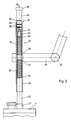
- the stimulus generator 1 and thus the Peltier element 2 and the heat exchanger 3 are mounted in a housing 4 such that the stimulus generator 1, the Peltier element 2 and the heat exchanger 3 can be displaced along an axis 5.
- the displacement takes place against the force of a pressure device 6, which has a spring 7 and a stop 8.
- the stop 8 is adjustable coaxially to the axis 5 by means of a knurled screw 9, so that the spring 7 is adjustable.
- the head of the knurled screw 9 lies outside the housing 4, during which the threaded part of the knurled screw 9 cooperates with the stop 8 with a corresponding thread.
- the knurled screw 9 is turned according to an arrow 10, whereby the stop 8 relieves the spring 7.
- the spring 7 is loaded.
- the stimulus generator 1 has a projection 14 relative to the housing 4.
- the stimulation device is pressed onto the skin of the patient, who is not shown here, in such a way that an essentially flat contact surface 15 of the housing 4 rests on the patient's skin.
- the stimulus generator 1 is displaced in the direction of an arrow 16 against the force of the spring 7 on the axis 5.
- the spring 7 is supported on the one hand on the stop 8 and on the other hand on the stimulus generator 1 or the heat exchanger 3.
- the tension of the spring 7 is adjusted by turning the knurled screw 9, the respective position or the respective tension of the spring 7 being readable on the display device 11. It is thus ensured that the stimulator 1 is always applied to the patient's skin with the same reproducible pressure.
- the now heating or cooling of the stimulus generator 1 takes place by means of corresponding power supplies of the Peltier element 2, which are not shown here.
- the heat exchanger 3 is connected to the warm side of the Peltier element. Elements 2 thermally connected.
- the heat exchanger 3 has a plurality of ribs in its interior in order to achieve the best possible heat transfer.
- the cooling liquid is supplied to the heat exchanger 3 via a supply line 17 and is removed again from a discharge line 18.
- the stimulation device according to FIG. 2 differs essentially from that of FIG. 1 in that a different position of the stop 8 is set with the aid of the knurled screw 9, that is to say the tension of the spring 7 is changed.
- the spring 7 is shown here in the compressed state, that is to say in the state in which the contact surface 15 rests on the patient's skin and thus the stimulus generator 1 or its outer surface comes to lie in a plane 19 with the contact surface 15. In the state shown here, the stimulus generator 1 is acted against by the spring 7 against the direction of the arrow 16 with a force set on the pressure device 6.
- the magnitude of the force can be varied by adjusting the stop 8 using the knurled screw 9, so that depending on the operating position, that is to say a horizontal, vertical arrangement or inclined position, both a compensation of the dead weight of the parts connected to the stimulator 1 takes place as well as a change in the contact pressure of the stimulus generator 1 is possible in a certain range. This makes it possible to achieve an always reproducible contact pressure of the stimulus generator 1 and to adapt the contact pressure to the respective conditions.
- FIG. 3 shows the part of a holding arm 20 to which a second pressure device 21 is attached.
- the holding arm 20 has a plurality of joints 22, so that it is pivotable and adjustable overall in all directions.
- the second pressure device 21 is fixedly connected to one end of the holding arm 20.
- the second pressure device 21 has a sleeve 23 in which a shaft 24, which is fixedly connected to the housing 4, is guided.
- a first compression spring 25 and a second compression spring 26 are provided, which hold the shaft 24 in a middle position.
- the compression springs 25 and 26 are each supported on a support 27 or 28 of the sleeve 23 and on supports 29 or 30 of the shaft 24.
- the support 30 is formed by an extension part 31 that can be screwed onto the shaft 24.
- the extension part 31 has a thread 32 which cooperates with a corresponding counter thread 33 of the shaft 24.
- the axial extent of the extension part 31 is chosen such that the extension part 31 projects beyond an end 34 of the sleeve 23.
- a stop 35 is provided which limits the axial mobility of the shaft 24 in the sleeve 23 in the direction of an arrow 36.
- the limitation in the direction opposite the arrow 36 is carried out by a second stop 37 which is fastened to the housing 4.
- the extension part 31 has notches 38 in the area of the end 34 of the sleeve 23, which in conjunction with the end 34 form a display 39 for the respective position of the shaft 24.
- the shaft 24 is fixedly connected to the housing 4 via the stop 37.
- the holding arm 20 is pivoted and aligned in its joints 22 such that the housing 4 or the stimulator 1 is oriented in the direction of that part of the patient's body on which the stimulator 1 is to be placed.
- the position of the shaft 24 or of the extension part 31 relative to the sleeve 23 is read off on the display 39. This depends on the respective position of the housing 4, that is to say whether the housing 4 is oriented in the direction of the arrow 36 or against the direction of the arrow 36, perpendicularly or obliquely to the arrow 36. This is due to the weight acting in the direction of arrow 36.
- one of the compression springs 25 and 26 is loaded and the other compression spring 25 and 26 is relieved.
- the housing 4 and thus the stimulus generator 1 is now adjusted via the holding arm 20 in such a way that the housing 4 or the contact surface 15 of the housing 4 comes to rest on the patient's skin with a predetermined contact pressure.
- the prevailing contact pressure is shown on the display 39 in connection with the previously read value. This ensures that the housing 4 always rests on the corresponding body part of the patient with the same, previously determinable contact pressure. It is also advantageous that the patient can get rid of the stimulator 1 in emergencies, for example when the stimulator 1 reaches a too high temperature, by moving the stimulator 1 and the housing 4 against the arrow 36.
- the shaft 24 is held in a middle position on the one hand, thus ensuring freedom of movement in both directions and on the other hand achieving the advantage that the housing 4 and the Stimulator 1 can be used in any position.
- One and the same contact pressure is thus achieved both on a patient's hand, ie when the housing is arranged overhead, and on a patient's foot. Of course, this also applies to any other position between these positions.
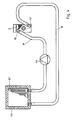
- FIG 4 shows a schematic representation of the cooling circuit of the stimulation device.
- the heat exchanger 3 has a connecting piece 40 and 41 for the discharge line 18 and the supply line 17, which are made of flexible material.
- a second heat exchanger 42 is provided, which is in heat-conducting connection with a second Peltier element 43.
- the second Peltier element 43 is arranged or is fed in such a way that its cold side bears against the heat exchanger 42, so that additional cooling is achieved.
- a pump 44 is provided to convey the cooling liquid at least in one of the supply line 17 or the discharge line 18.
- the arrangement of the second Peltier element 43 on the second heat exchanger 42 has the advantage that a large amount of heat can be dissipated in a short time and thus the cooling capacity of the stimulation device is considerably increased. This is important because the cooling time has had an impact on the test results.
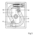
- connecting piece 40 and 41 of the heat exchanger 3 are shown again.
- the connecting pieces 40 and 41 are designed in such a way that the forces caused by the dynamic pressure of the liquid act in a plane perpendicular to the arrow 16, see FIG. 2, that is to say on the plane of the drawing corresponding to FIG. 5.
- This measure also serves to keep the contact pressure of the stimulus generator 1 constant or reproducible and thus also to ensure the reproducibility of the examination results.
Landscapes
- Health & Medical Sciences (AREA)
- Life Sciences & Earth Sciences (AREA)
- Pain & Pain Management (AREA)
- Heart & Thoracic Surgery (AREA)
- Molecular Biology (AREA)
- Psychiatry (AREA)
- Biophysics (AREA)
- Pathology (AREA)
- Engineering & Computer Science (AREA)
- Biomedical Technology (AREA)
- Hospice & Palliative Care (AREA)
- Medical Informatics (AREA)
- Physics & Mathematics (AREA)
- Surgery (AREA)
- Animal Behavior & Ethology (AREA)
- General Health & Medical Sciences (AREA)
- Public Health (AREA)
- Veterinary Medicine (AREA)
- Thermotherapy And Cooling Therapy Devices (AREA)
- Finger-Pressure Massage (AREA)
Abstract
Stimulationsvorrichtung zur Bestimmung des Temperaturempfindens der Haut eines Patienten, mit einem in einem Gehäuse (4) angeordneten Reizgeber (1), der über ein Peltier-Element (2) aufheizbar bzw. abkühlbar ist. Der Reizgeber (1) ist in dem Gehäuse (4) entlang einer Achse (5) beweglich angeordnet und weist in Ruhestellung gegenüber dem Gehäuse (4) einen Überstand (14) auf. Es ist eine erste Andruckeinrichtung (6) vorgesehen, die mit dem Reizgeber (1) derart zusammenwirkt, daß der Reizgeber (1) unter Aufbringung einer Kraft in Richtung der Achse (5) solange verschiebbar ist, bis der Überstand (14) zu Null wird. Die Kraft ist durch die Andruckeinrichtung (6) fest vorgegeben oder einstellbar.
Description
- Die Erfindung geht aus von einer Stimulationsvorrichtung zur Bestimmung des Temperatur- und Schmerzempfindens eines Patienten mittels kutaner Kontaktstimulation, mit einem in einem Gehäuse angeordneten Reizgeber, der über ein Peltier-Element aufheizbar bzw. abkühlbar ist.
- Die Untersuchung des Temperatur- und Schmerzempfindens dient bei zahlreichen Erkrankungen, wie beispielsweise der diabetischen Neuropathie, der Frühdiagnostik sowie der Überprüfung der Krankheits- und Therapieverläufe. Untersucht werden das Warm-Kalt-Empfinden sowie die Wahrnehmungsfähigkeit für Hitzeschmerz, die beide den Funktionsstatus kleiner Nervenfasern wiederspiegeln. Der Reizgeber wird mit einer geeigneten Körperstelle des Patienten in Kontakt gebracht. Die Temperaturen des Reizgebers werden, jeweils von einer mittleren Temperatur ausgehend, erhöht oder gesenkt. Der Patient meldet, wenn er eine Temperaturänderung bemerkt (Warm-Kalt-Empfindung) oder wenn er die erste Schmerzempfindung wahrnimmt (Schmerzempfindung). Bei einem Patienten mit beispielsweise diabetischer Neuropathie ist sowohl die Warm-Kalt-Empfindung als auch die Scherzempfindung zu höheren Werten verlagert. Dies trifft auch bei anderen Erkrankungen mit Schädigung der dünnen Nervenfasern zu, so daß in diesen Fällen mit der genannten Methode Diagnose und Therapievalution möglich ist.
- Eine Stimulationsvorrichtung der eingangs beschriebenen Art ist aus einer Werbeschrift der Firma Medelec Ltd., betitelt "TTT" bekannt. Der Reizgeber ist in dem Gehäuse angeordnet und fest mit dem Gehäuse verbunden. Das Peltier-Element wird, entsprechend der Richtung des dem Peltier-Element zugeführten Stroms, aufgeheizt bzw. abgekühlt. Der Reizgeber steht mit dem Peltier-Element derart in Verbindung, daß die Wärme auf den Reizgeber entsprechend übertragen wird. Die Stimulationsvorrichtung wird mit einer geeigneten Körperstelle des Patienten, beispielsweise der Hand oder dem Fuß, in Kontakt gebracht. Bei den sich daran anschließenden Untersuchungen hat es als nachteilig herausgestellt, daß die Untersuchungsergebnisse vom Auflagedruck des Stimulators abhängig sind. Der Auflagedruck ist bei den bisher bekannten Vorrichtungen nicht exakt einstellbar. Dies erhöht den Meßfehler und verringert daher die Meßzuverlässigkeit. Die DE-OS 33 09 093 zeigt ein Gerät zur Messung der Durchblutungsfunktion der Haut, wobei eine gewisse Hautpartie aufgeheizt wird und der Temperaturverlauf an einer nicht aufgeheizten Stelle inmitten des beheizten Gebiets gemessen wird. Die Vorrichtung weist ein Gehäuse auf, in welches ein fluidbetätigter Kolben, abgestützt auf einer Rückholfeder, beweglich angeordnet ist, der eine Baugruppe aus dem Peltier-Element trägt, so daß auf diese Art und Weise die Anlage des Peltier-Elements an der Haut des Patienten möglich ist. Die auf das Gehäuse einwirkende Reaktionskraft des pneumatischen Drucks setzt voraus, daß das Gewicht des Gehäuses entsprechend groß ist, damit sich diese Reaktionskraft ausbilden kann und nicht zu einem Abheben des Gehäuses von der Haut des Patienten führt. Diese Konstruktion setzt weiterhin voraus,daß das Gehäuse nur von oben senkrecht nach unten weisend auf die Haut des Patienten aufgesetzt werden kann. Eine umgekehrte Gebrauchslage oder gar eine Gebrauchslage an einer senkrechten Stelle des Patienten, beispielsweise an der Wange des Patienten oder im Fußbereich, ist nicht möglich. Auf jeden Fall aber wird mit dem nicht unbeträchtlichen Gewicht des Gehäuses der Patient belastet, so daß die Gefahr besteht, daß der zu untersuchende Bereich durch diese Gewichtskraft abgeschnürt wird, so daß aus diesem Grund bereits eine geringere Durchblutung des betr. Bereichs stattfindet, der das Meßergebnis natürlich verfälscht.
- Die DE-OS 29 12 349 zeigt eine Vorrichtung zur Bestimmung des Feuchtigkeitszustands der menschlichen Haut, wobei dort ein Elektrodenhalter gegenüber einem Gehäuse mit Überstand auf einer Feder gelagert angeordnet ist und entgegen der Kraft der Feder auf die Haut des Patienten aufsetzbar und andrückbar ist, bis der Überstand verschwunden ist. Das Andrücken an der menschlichen Haut geschieht offensichtlich per Hand und ist damit bezüglich der Anpreßkraft variabel und nicht reproduzierbar.
- Der Erfindung liegt daher die Aufgabe zugrunde, eine Stimulationsvorrichtung der eingangs beschriebenen Art so weiterzubilden, daß weitgehend reproduzierbare Untersuchungsergebnisse in allen Gebrauchslagen erzielbar sind.
- Erfindungsgemäß wird dies bei der Stimulationsvorrichtung der eingangs beschriebenen Art dadurch erreicht, daß der Reizgeber in dem Gehäuse entlang einer Achse beweglich angeordnet ist und in Ruhestellung gegenüber einer Auflagefläche des Gehäuses einen Überstand aufweist, daß eine erste Andruckeinrichtung für den Reizgeber und eine zweite Andruckeinrichtung für die Auflagefläche des Gehäuses vorgesehen ist, daß die erste Andruckeinrichtung mit dem Reizgeber derart zusammenwirkt, daß der Reizgeber unter Aufbringung einer Kraft in Richtung der Achse solange verschiebbar ist, bis der Überstand zu Null wird, wobei die Kraft über die erste Andruckeinrichtung einstellbar ist, und daß die zweite Andruckeinrichtung mit dem Gehäuse derart zusammenwirkt, daß die Auflagefläche des Gehäuses unter Aufbringung einer zweiten einstellbaren Kraft in Richtung der Achse feststellbar ist. Der Reizgeber ist also hier nicht mehr fest mit dem Gehäuse verbunden, sondern entlang einer Achse beweglich angeordnet. In der Ruhestellung, d h. wenn der Reizgeber nicht in Kontakt mit einer Körperstelle des Patienten gebracht ist, weist der Reizgeber einen Überstand gegenüber dem Gehäuse auf, ragt also um einen bestimmten Betrag aus dem Gehäuse heraus. Die Andruckeinrichtung ist mit dem Reizgeber derart verbunden, daß beim Verschieben des Reizgebers in Richtung der Achse eine bestimmte Kraft aufgewendet werden muß. Dabei ist die aufzuwendende Kraft durch die erste Andruckeinrichtung einstellbar. Bei Verwendung der Stimulationsvorrichtung wird das Gehäuse mit der ausgewählten Körperstelle des Patienten in der jeweiligen Gebrauchslage, also in waagerechter oder senkrechter Anordnung oder in Schräglage, über die zweite Andruckeinrichtung mit der Haut des Patienten in Kontakt gebracht. Dabei ist wichtig, daß das Gehäuse der Stimulationsvorrichtung auf der Haut des Patienten gerade anliegt bzw. daß von dem Gehäuse nur ein relativ geringer Druck auf die Haut aufgebracht wird. Der Reizgeber wird dann von der Andruckeinrichtung mit der vorgegebenen Kraft an die Haut des Patienten gedrückt. Damit wird sichergestellt, daß der Reizgeber bei allen Untersuchungen, unabhängig von der Körperstelle des Patienten, mit dem vorgegebenen Druck auf der Haut des Patienten aufliegt. Dieser reproduzierbare Auflagedruck hat sich als eine wichtige Voraussetzung zum Erhalten reproduzierbarer Untersuchungsergebnisse herausgestellt. In Abhängigkeit von dem Auflagedruck werden neben den thermosensiblen Nervenfasern mechanosensible durch die Druckkräfte mehr oder weniger stark aktiviert. Diese Kostimulation kann Einfluß auf das Temperatur- und Schmerzempfinden ausüben. Dadurch bedingt ändert sich auch das Temperaturempfinden, welches, wie oben beschrieben, als Maß für diagnostische Zwecke herangezogen wird. Ebenfalls ist der Wärmeübergang von dem Reizgeber auf die Haut abhängig von dem Auflagedruck. Bei der im Stand der Technik bekannten Stimulationsvorrichtung ist der Auflagedruck abhängig von einer Mehrzahl von Parametern,so daß letztendlich die Untersuchungsergebnisse aufgrund der Abhängigkeit des Auflagedrucks erheblich schwanken. Im Gegensatz wird bei der vorliegenden Erfindung der Auflagedruck stets konstantgehalten. Auch bei der Auswahl unterschiedlicher Körperstellen, also beispielsweise bei Messung des Temperaturempfindens einmal an der Hand und ein anderes Mal an dem Fuß des Patienten bzw. bei verschiedenen Patienten, bei denen die Hände und Füße auch unterschiedliche Gestalt aufweisen, ist der konstante Auflagedruck stets gewährleistet.
- Die erste Andruckeinrichtung kann eine Feder aufweisen, die sich einerseits an dem Reizgeber und andererseits an einem in dem Gehäuse angeordneten Anschlag abstützt. Die Verwendung der Feder, vorzugsweise als Druckfeder, hat den Vorteil, daß sie relativ einfach herstellbar ist bzw. daß sie käuflich zu einem günstigen Preis erworben werden kann. Dabei erfüllt sie die ihr zugeordnete Aufgabe, nämlich auf den Reizgeber eine bestimmte Kraft auszuüben, zuverlässig. Die Feder stützt sich einerseits an dem Reizgeber selber ab und andererseits an dem im Gehäuse angeordneten Anschlag. Dabei kann der sich im Gehäuse angeordnete Anschlag zur Verstellung der Größe der auf den Reizgeber wirkenden Kraft, vorzugsweise koaxial zur Bewegungsrichtung des Reizgebers, verstellbar sein. Diese Verstellung kann durch eine einfache Rändelschraube erfolgen, deren Kopf aus dem Gehäuse geführt ist. Die Rändelschraube wirkt dann mit dem Anschlag derart zusammen, daß durch das Drehen der Rändelschraube der Anschlag koaxial zur Bewegungsrichtung des Reizgebers verschoben wird. Damit kann dann die Federspannung und somit letztendlich auch die Größe der auf den Reizgeber wirkenden Kraft den jeweiligen Verhältnissen angepaßt werden. Um die einmal eingestellte Kraft auch später wieder reproduzieren zu können, kann eine die auf den Reizgeber wirkende Kraft bzw. die Stellung des Anschlags wiedergebende Anzeigeeinrichtung vorgesehen sein. Die Anzeigeeinrichtung kann dann beispielsweise ein in dem Gehäuse angeordnetes Fenster aufweisen, durch die dann eine entsprechende Markierung, an der ein an dem Anschlag angeordneter Zeiger vorbeiläuft, abgelesen werden kann.
- Die zweite Andruckeinrichtung kann einen in allen Richtungen schwenk- und verstellbaren Haltearm aufweisen, wobei das Gehäuse an der zweiten Andruckeinrichtung gelagert ist. Das eine Ende des Haltearms ist an einem feststehenden Gegenstand, beispielweise einem Tischbein o. dgl., befestigt. An dem anderen Ende des Haltearms ist das Gehäuse vorgesehen, wobei zwischen dem Haltearm und dem Gehäuse die zweite Andruckeinrichtung angeordnet ist. Die zweite Andruckeinrichtung sorgt dafür, daß das Gehäuse stets mit nahezu gleichbleibendem Druck auf der jeweiligen
- Körperstelle des Patienten anliegt. Dies ist insoweit wichtig, da somit sichergestellt ist, daß das Gehäuse tatsächlich auf der Haut des Patienten anliegt und somit die stets gleichbleibende Druckbelastung des Reizgebers auf der Haut des Patienten vorliegt. Weiterhin kann auch durch den auf die Haut ausgeübten Gehäusedruck eine Beeinflussung des Untersuchungsergebnisses auftreten. Auch der Gehäusedruck trägt zur mechanischen Kostimulation bei und kann so zu Veränderungen des Temperatur- und Schmerzempfindens führen. Außerdem kann bei längeren Untersuchungen, insbesondere bei Patienten mit Durchblutungsstörungen, ein zu hoher Gehäusedruck die Blutzirkulation unter und neben dem Stimulator beeinträchtigen. Dies führt über Veränderungen der Temperatur des kutanen und subkutanen Gewebes zu Variationen in der Empfindungsstärke. Insoweit trägt die zweite Andruckeinrichtung in Verbindung mit dem Haltearm zu der Reproduzierbarkeit der Untersuchungsergebnisse bei.
- Die zweite Andruckeinrichtung kann eine mit dem Gehäuse starr verbundene Welle aufweisen, wobei die Welle in einer an dem Haltearm befestigbaren Hülse beweglich geführt ist und wobei eine die Welle in einer vorzugsweise mittleren Position fixierenden Haltevorrichtung angeordnet sein kann. Die Haltevorrichtung kann derart ausgebildet und angeordnet sein, daß die Welle aus der fixierten Position unter Aufbringung einer Kraft verschiebbar ist. Die Haltevorrichtung kann vorzugsweise zwei Druckfedern aufweisen, wobei jeder Druckfeder eine Auflage an der Hülse und eine zweite Auflage an der Welle zugeordnet sind, und daß bei Belastung der einen Druckfeder die andere entlastet wird und umgekehrt. Die Haltevorrichtung kann eine Anzeige aufweisen, von der die Größe und die Richtung der auf den Druckfedern wirkenden Belastung ablesbar ist. Durch die Anordnung zweier Druckfedern ist gewährleistet, daß jeweils eine der beiden Druckfedern in Abhängigkeit davon, ob der Reizgeber über Kopf steht oder nicht, wirkt. Bevor das Gehäuse mit der Haut des Patienten in Kontakt gebracht wird, kann in der jeweiligen Position, also über Kopf oder nicht, schräg oder gerade, von der Anzeige die durch die Gewichtskraft hervorgerufene Kraft abgelesen werden. Anschließend wird das Gehäuse mit dem Reizgeber durch entsprechende Verstellung des Haltearms mit der Haut des Patienten in Kontakt gebracht und beispielsweise die eine Druckfeder durch Verschiebung der Hülse in Richtung des Gehäuses derart belastet, daß das Gehäuse mit einem bestimmten Auflagedruck auf der Haut des Patienten aufliegt. Der Auflagedruck ergibt sich aus dem angezeigten Wert vor der Auflage des Gehäuses auf die Haut in Verbindung mit dem nach der Auflage angezeigten Wert. Diese Anordnung hat auch den weiteren Vorteil, daß der Patient bei Überhitzung des Reizgebers durch beispielsweise einen Defekt nicht fest mit dem Reizgeber bzw. dem Gehäuse verbunden ist, sondern durch eine entsprechende Bewegung von diesem freikommen kann.
- Als ein weiterer, wenn auch nicht derart ausschlaggebender Einflußfaktor auf die Untersuchungsergebnisse hat sich herausgestellt, daß das Temperaturempfinden abhängig von den für den Aufheizvorgang bzw. für die Kühlung benötigten Kühlraten ist. Aussagekräftige Ergebnisse erhält man bei möglichst stabilen Heiz- bzw. Kühlraten. Dabei ist insbesondere der Kühlvorgang technisch schwieriger zu realisieren. Um eine möglichst stabile Kühlrate auch im unteren Temperaturbereich in der Reizphase zu erhalten sowie eine Rücksetzung zur "Baseline" zur Wiederherstellung der Prästimulationsbedingungen zu ermöglichen, kann dem Peltier-Element ein flüssigkeitsgekühlter Wärmetauscher zugeordnet sein und ein zweites, die Flüssigkeit des Wärmetauschers kühlendes Peltier-Element vorgesehen sein. Durch die Anordnung eines Wärmetauschers, der flüssigkeitsgekühlt ist, wird die Kühlleistung bereits in erheblichem Maße gesteigert. Das zweite Peltier-Element ist derart angeordnet bzw. wird derart angesteuert, daß die kalte Seite des Peltier-Elements mit der warmen Seite des Wärmetauschers in Verbindung steht und somit die Kühlflüssigkeit abkühlt. Damit kann die für die Kühlung benötigte Zeit in etwa halbiert werden bzw. kann die Kühlleistung in Grad/sec. in etwa verdoppelt werden.
- Die Erfindung wird anhand von bevorzugten Ausführungsbeispielen weiter beschrieben. Es zeigen:
- Figur 1 ein Ausführungsbeispiel einer Stimulationsvorrichtung,
- Figur 2 die Stimulationsvorrichtung gemäß Figur 1 nach Auflage auf die Haut eines Patienten,
- Figur 3 einen Haltearm mit einer zweiten Andruckeinrichtung für die Stimulationsvorrichtung,
- Figur 4 eine schematische Darstellung eines Kühlkreislaufs und
- Figur 5 eine Leitungsführung des Kühlkreislaufs.
- In Figur 1 ist eine erste Ausführungsform der erfindungsgemäßen Stimulationsvorrichtung dargestellt. Ein Reizgeber 1 ist mit einem Peltier-Element 2 leitend verbunden. Das Peltier-Element 2 wird von einem Wärmetauscher 3, der ebenfalls mit dem Peltier-Element in Verbindung steht, gekühlt. Der Reizgeber 1 und somit das Peltier-Element 2 und der Wärmetauscher 3 sind in einem Gehäuse 4 derart gelagert, daß der Reizgeber 1, das Peltier-Element 2 und der Wärmetauscher 3 entlang einer Achse 5 verschiebbar sind. Die Verschiebung erfolgt entgegen der Kraft einer Andruckeinrichtung 6, die eine Feder 7 und einen Anschlag 8 aufweist. Der Anschlag 8 ist mit Hilfe einer Rändelschraube 9 koaxial zu der Achse 5 verstellbar, so daß die Feder 7 einstellbar ist. Der Kopf der Rändelschraube 9 liegt außerhalb des Gehäuses 4, währenddessen das Gewindeteil der Rändelschraube 9 mit einem entsprechenden Gewinde mit dem Anschlag 8 zusammenarbeitet. Zum Verstellen des Anschlags 8 wird die Rändelschraube 9 entsprechend einem Pfeil 10 gedreht, wodurch der Anschlag 8 die Feder 7 entlastet. Bei Drehung der Rändelschraube 9 in entgegengesetzter Richtung des Pfeils 10 findet eine Belastung der Feder 7 statt. Eine Anzeigeeinrichtung 11, die im wesentlichen ein Fenster 12 und einen Zeiger 13 sowie eine hier nicht weiter dargestellte Markierung aufweist, dient zum Ablesen der jeweiligen Stellung des Anschlags 8 bzw. der eingestellten Spannung der Feder 7. Im unbelasteten Zustand, also wenn die Stimulationsvorrichtung noch nicht mit der Haut eines Patienten in Kontakt gebracht ist, weist der Reizgeber 1 einen Überstand 14 gegenüber dem Gehäuse 4 auf.
- Im Folgenden wird nun die Funktionsweise der Stimulationsvorrichtung beschrieben. Zur Untersuchung des Temperaturempfindens wird die Stimulationsvorrichtung auf die Haut des hier nicht weiter dargestellten Patienten derart angedrückt, daß eine im wesentlichen ebene Anlagefläche 15 des Gehäuses 4 auf der Haut des Patienten aufliegt. Der Reizgeber 1 wird dabei in Richtung eines Pfeils 16 entgegen der Kraft der Feder 7 auf der Achse 5 verschoben. Die Feder 7 stützt sich einerseits an dem Anschlag 8 und andererseits an dem Reizgeber 1 bzw. dem Wärmetauscher 3 ab. Die Spannung der Feder 7 wird durch Drehen der Rändelschraube 9 verstellt, wobei die jeweilige Stellung bzw. die jeweilige Spannung der Feder 7 an der Anzeigeeinrichtung 11 ablesbar ist. Es ist somit sichergestellt, daß der Reizgeber 1 stets mit dem gleichen reproduzierbaren Druck auf der Haut des Patienten anliegt. Das nun erfolgende Aufheizen bzw. Abkühlen des Reizgebers 1 erfolgt durch entsprechende, hier nicht weiter dargestellte Stromzuführungen des Peltier-Elements 2. Um eine möglichst kurze Abkühlzeit bzw. eine möglichst große Abkühlrate zu erreichen, ist der Wärmetauscher 3 mit der warmen Seite des Peltier-Elements 2 wärmeleitend verbunden. Der Wärmetauscher 3 weist dabei in seinem Innern eine Vielzahl von Rippen auf, um einen möglichst guten Wärmeübergang zu erreichen. Dem Wärmetauscher 3 wird die Kühlflüssigkeit über eine Zufuhrleitung 17 zugeführt und von einer Abfuhrleitung 18 wieder abgeführt.
- Die Stimulationsvorrichtung entsprechend der Figur 2 unterscheidet sich im wesentlichen von derjenigen der Figur 1 dadurch, daß mit Hilfe der Rändelschraube 9 eine andere Stellung des Anschlags 8 eingestellt ist, daß also die Spannung der Feder 7 verändert ist. Die Feder 7 ist hierbei in zusammengedrücktem Zustand gezeigt, also in demjenigen Zustand, bei dem die Anlagefläche 15 auf der Haut des Patienten anliegt und somit der Reizgeber 1 bzw. dessen äußere Oberfläche mit der Anlagefläche 15 in einer Ebene 19 zu liegen kommt. In dem hier dargestellten Zustand wird der Reizgeber 1 entgegen der Richtung des Pfeils 16 durch die Feder 7 mit einer an der Andruckeinrichtung 6 eingestellten Kraft beaufschlagt. Die Größe der Kraft ist durch Verstellen des Anschlags 8 mit Hilfe der Rändelschraube 9 variierbar, so daß je nach Betriebslage, also waagerechter, senkrechter Anordnung oder Schräglage, sowohl eine Kompensation des Eigengewichts der mit dem Reizgeber 1 verbundenen Teile erfolgt als auch eine Veränderung des Auflagedrucks des Reizgebers 1 in einem bestimmten Bereich möglich wird. Damit ist es möglich, einen stets reproduzierbaren Auflagedruck des Reizgebers 1 zu erreichen und den Auflagedruck auch den jeweiligen Verhältnissen anzupassen.
- In Figur 3 ist der eine Teil eines Haltearms 20 gezeigt, an dem eine zweite Andruckeinrichtung 21 befestigt ist. Der Haltearm 20 weist eine Vielzahl von Gelenken 22 auf, so daß er insgesamt in allen Richtungen schwenk- und verstellbar ist. Die zweite Andruckeinrichtung 21 ist mit dem einen Ende des Haltearms 20 fest verbunden. Die zweite Andruckeinrichtung 21 weist eine Hülse 23 auf, in der eine Welle 24, die mit dem Gehäuse 4 fest verbunden ist, geführt wird. Es sind eine erste Druckfeder 25 und eine zweite Druckfeder 26 vorgesehen, die die Welle 24 in einer mittleren Position halten. Die Druckfedern 25 und 26 stützen sich dabei jeweils an einer Auflage 27 bzw. 28 der Hülse 23 und an Auflagen 29 bzw. 30 der Welle 24 ab. Zur Bildung der Auflage 29 ist der Durchmesser der Welle 24 reduziert, die Auflage 30 wird durch ein auf die Welle 24 aufschraubbares Verlängerungsteil 31 gebildet. Das Verlängerungsteil 31 weist dafür ein Gewinde 32 auf, welches mit einem entsprechenden Gegengewinde 33 der Welle 24 zusammenarbeitet. Die axiale Erstreckung des Verlängerungsteils 31 ist derart gewählt, daß das Verlängerungsteil 31 über einem Ende 34 der Hülse 23 hinausragt. An dem dem Gewinde 32 gegenüberliegenden Ende des Verlängerungsteils 31 ist ein Anschlag 35 vorgesehen, der die axiale Beweglichkeit der Welle 24 in der Hülse 23 in Richtung eines Pfeils 36 begrenzt. Die Begrenzung in Richtung entgegen des Pfeils 36 erfolgt durch einen zweiten Anschlag 37, der an dem Gehäuse 4 befestigt ist. Das Verlängerungsteil 31 weist im Bereich des Endes 34 der Hülse 23 Einkerbungen 38 auf, die in Verbindung mit dem Ende 34 eine Anzeige 39 für die jeweilige Stellung der Welle 24 bilden. Die Welle 24 ist über den Anschlag 37 fest mit dem Gehäuse 4 verbunden.
- Zur Durchführung der Untersuchung wird der Haltearm 20 in seinen Gelenken 22 derart verschwenkt und ausgerichtet, daß das Gehäuse 4 bzw. der Reizgeber 1 in Richtung derjenigen Körperstelle des Patienten ausgerichtet ist, auf die der Reizgeber 1 aufgelegt werden soll. In diesem Zustand, also wenn das Gehäuse 4 bzw. der Reizgeber 1 noch nicht auf der Haut des Patienten aufliegt, wird an der Anzeige 39 die Stellung der Welle 24 bzw. des Verlängerungsteils 31 zu der Hülse 23 abgelesen. Dies ist abhängig von der jeweiligen Lage des Gehäuses 4, also ob das Gehäuse 4 in Richtung des Pfeils 36 oder entgegen der Richtung des Pfeils 36, senkrecht oder schräg zu dem Pfeil 36 ausgerichtet ist. Dies begründet sich durch die in Richtung des Pfeils 36 wirkende Gewichtskraft. Entsprechend wird eine der Druckfedern 25 bzw. 26 belastet und die entsprechend andere Druckfeder 25 bzw. 26 entlastet. Das Gehäuse 4 und damit der Reizgeber 1 wird nun über den Haltearm 20 derart verstellt, daß das Gehäuse 4 bzw. die Auflagefläche 15 des Gehäuses 4 mit einem vorgegebenen Auflagedruck auf der Haut des Patienten zum Anliegen kommt. Der jeweils vorhandene Auflagedruck ist an der Anzeige 39 in Verbindung mit dem vorher abgelesenen Wert angezeigt. Damit ist sichergestellt, daß das Gehäuse 4 immer mit dem gleichen, vorher bestimmbaren Auflagedruck auf der entsprechenden Körperstelle des Patienten aufliegt. Weiterhin vorteilhaft ist, daß der Patient in Notfällen, beispielsweise wenn der Reizgeber 1 eine zu hohe Temperatur erreicht, sich von dem Reizgeber 1 befreien kann, indem er den Reizgeber 1 und das Gehäuse 4 entgegen des Pfeils 36 verschiebt. Durch die geschickte Anordnung des doppelt wirkenden Federsystems, also durch die Anordnung der Druckfedern 25 und 26, die jeweils in der einen Richtung wirken, wird die Welle 24 einerseits in einer mittleren Position gehalten und somit eine Bewegungsfreiheit in beiden Richtungen gewährleistet und andererseits der Vorteil erreicht, daß das Gehäuse 4 und der Reizgeber 1 in jeder beliebigen Position verwendbar ist. Ein und derselbe Auflagedruck wird also sowohl an der Hand eines Patienten, d. h. wenn das Gehäuse über Kopf angeordnet ist, als auch an einem Fuß des Patienten erreicht. Natürlich gilt das ebenso für jede x-beliebige andere, zwischen diesen Positionen liegende Stellung.
- Figur 4 zeigt eine schematische Darstellung des Kühlkreislaufs der Stimulationsvorrichtung. Der Wärmetauscher 3 weist für die Abfuhrleitung 18 und die Zufuhrleitung 17, die aus flexiblem Material hergestellt sind, je einen Anschlußstutzen 40 und 41 auf. Am anderen Ende der Zufuhrleitung 17 bzw. Abfuhrleitung 18 ist ein zweiter Wärmetauscher 42 vorgesehen, der mit einem zweiten Peltier-Element 43 wärmeleitend in Verbindung steht. Das zweite Peltier-Element 43 ist dabei derart angeordnet bzw. wird derart gespeist, daß seine kalte Seite an dem Wärmetauscher 42 anliegt, so daß eine zusätzliche Kühlung erzielt wird. Zur Förderung der Kühlflüssigkeit ist zumindest in einer der Zufuhrleitung 17 oder der Abfuhrleitung 18 eine Pumpe 44 vorgesehen. Die Anordnung des zweiten Peltier-Elements 43 an dem zweiten Wärmetauscher 42 hat den Vorteil, daß in kurzer Zeit eine große Wärmemenge abgeführt werden kann und somit die Kühlleistung der Stimulationsvorrichtung erheblich erhöht wird. Dies ist insoweit wichtig, da die Abkühlzeit einen Einfluß auf die Untersuchungsergebnisse gezeigt hat.
- In der Figur 5 sind noch einmal die Anschlußstutzen 40 und 41 des Wärmetauschers 3 dargestellt. Die Anschlußstutzen 40 und 41 sind derart ausgebildet, daß die durch den Staudruck der Flüssigkeit hervorgerufenen Kräfte in einer Ebene senkrecht zu dem Pfeil 16, siehe Figur 2, wirken, also an der Zeichenebene entsprechend der Figur 5. Dies wird dadurch erreicht, daß die Anschlußstutzen 40 und 41 eine L-förmige Gestalt aufweisen, wobei der eine Schenkel der Anschlußstutzen 40 bzw. 41 in der Zeichenebene der Figur 5 liegt und als Einlaß benutzt wird, während der andere Schenkel senkrecht zu der Zeichenebene angeordnet ist und mit dem Wärmetauscher 3 in Verbindung steht. Dies hat den Vorteil, daß beispielsweise Schwankungen der Geschwindigkeit des Kühlmittels, die durch unterschiedliche Positionierung der Stimulationsvorrichtung auftreten können, nahezu keine Auswirkungen in Richtung der Achse 5 besitzen, also den Anpreßdruck des Reizgebers 1 nicht beeinflussen. Auch diese Maßnahme dient somit zur Konstanthaltung bzw. Reproduzierbarkeit des Anpreßdrucks des Reizgebers 1 und damit auch zur Sicherstellung der Reproduzierbarkeit der Untersuchungsergebnisse.
-
- 1 = Reizgeber
- 2 = Peltier-Element
- 3 = Wärmetauscher
- 4 = Gehäuse
- 5 = Achse
- 6 = Andruckeinrichtung
- 7 = Feder
- 8 = Anschlag
- 9 = Rändelschraube
- 10 = Pfeil
- 11 = Anzeigeeinrichtung
- 12 = Fenster
- 13 = Zeiger
- 14 = Überstand
- 15 = Auflagefläche
- 16 = Pfeil
- 17 = Zufuhrleitung
- 18 = Abfuhrleitung
- 19 = Ebene
- 20 = Haltearm
- 21 = zweite Andruckeinrichtung
- 22 = Gelenk
- 23 = Hülse
- 24 = Welle
- 25 = Druckfeder
- 26 = Druckfeder
- 27 = Auflage
- 28 = Auflage
- 29 = Auflage
- 30 = Auflage
- 31 = Verlängerungsteil
- 32 = Gewinde
- 33 = Gegengewinde
- 34 = Ende
- 35 = Anschlag
- 36 = Pfeil
- 37 = Anschlag
- 38 = Einkerbung
- 39 = Anzeige
- 40 = Anschlußstutzen
- 41 = Anschlußstutzen
- 42 = Wärmetauscher
- 43 = zweites Peltier-Element
- 44 = Pumpe
Claims (10)
1. Stimulationsvorrichtung zur Bestimmung des Temperatur- und Schmerzempfindens eines Patienten mittels kutaner Kontaktstimulation, mit einem in einem Gehäuse angeordneten Reizgeber, der über ein Peltier-Element aufheizbar bzw. abkühlbar ist, dadurch gekennzeichnet, daß der Reizgeber (1) in dem Gehäuse (4) entlang einer Achse (5) beweglich angeordnet ist und in Ruhestellung gegenüber einer Auflagefläche (15) des Gehäuses (4) einen Überstand (14) aufweist, daß eine erste Andruckeinrichtung (6) für den Reizgeber (1) und eine zweite Andruckeinrichtung (21) für die Auflagefläche (15) des Gehäuses (4) vorgesehen ist, daß die erste Andruckeinrichtung (6) mit dem Reizgeber (1) derart zusammenwirkt, daß der Reizgeber (1) unter Aufbringung einer Kraft in Richtung der Achse (5) solange verschiebbar ist, bis der Überstand (14) zu Null wird, wobei die Kraft über die erste Andruckeinrichtung (6) einstellbar ist, und daß die zweite Andruckeinrichtung (21) mit dem Gehäuse (4) derart zusammenwirkt, daß die Auflagefläche (15) des Gehäuses (4) unter Aufbringung einer zweiten einstellbaren Kraft in Richtung der Achse (5) feststellbar ist.
2. Stimulationsvorrichtung nach Anspruch 1, dadurch gekennzeichnet, daß die erste Andruckeinrichtung (6) eine Feder (7) aufweist, die sich einerseits an dem Reizgeber (1) und andererseits an einem in dem Gehäuse (4) angeordneten Anschlag (8) abstützt.
3. Stimulationsvorrichtung nach Anspruch 2, dadurch gekennzeichnet, daß der im Gehäuse (4) angeordnete Anschlag (8) zur Verstellung der Größe der auf den Reizgeber (1) wirkenden Kraft vorzugsweise koaxial zur Bewegungsrichtung des Reizgebers (1) verstellbar ist.
4. Stimulationsvorrichtung nach einem der Ansprüche 1 bis 3, dadurch gekennzeichnet, daß eine die auf den Reizgeber (1) wirkende Kraft bzw. die Stellung des Anschlags (8) wiedergebende Anzeigeeinrichtung (11) vorgesehen ist.
5. Stimulationsvorrichtung nach Anspruch 1, dadurch gekennzeichnet, daß die zweite Andruckeinrichtung (21) einen in allen Richtungen schwenk- und verstellbaren Haltearm (20) aufweist, und daß das Gehäuse an der zweiten Andruckeinrichtung (21) gelagert ist.
6. Stimulationsvorrichtung nach Anspruch 5, dadurch gekennzeichnet, daß die zweite Andruckeinrichtung (21) eine mit dem Gehäuse (4) starr verbundene Welle (24) aufweist, daß die Welle (24) in einer an dem Haltearm (20) befestigbaren Hülse (23) beweglich geführt ist, und daß eine die Welle (24) in einer vorzugsweise mittleren Position fixierende Haltevorrichtung angeordnet ist.
7. Stimulationsvorrichtung nach Anspruch 6, dadurch gekennzeichnet, daß die Haltevorrichtung derart ausgebildet und angeordnet ist, daß die Welle (24) aus der fixierten Position unter Aufbringung einer Kraft verschiebbar ist.
8. Stimulationsvorrichtung nach Anspruch 6 oder 7, dadurch gekennzeichnet, daß die Haltevorrichtung vorzugsweise zwei Druckfedern (25, 26) aufweist, daß jeder Druckfeder (25, 26) eine Auflage (27, 28) an der Hülse (23) und eine zweite Auflage (29, 30) an der Welle (24) zugeordnet sind, und daß bei Belastung der einen Druckfeder (25, 26) die andere entlastet wird und umgekehrt.
9. Stimulationsvorrichtung nach Anspruch 8, dadurch gekennzeichnet, daß die Haltevorrichtung eine Anzeige (39) aufweist, von der die Größe und die Richtung der auf den Druckfedern (25, 26) wirkenden Belastung ablesbar ist.
10. Stimulationsvorrichtung nach einem der Ansprüche 1 bis 9, dadurch gekennzeichnet, daß dem Peltier-Element (2) ein flüssigkeitsgekühlter Wärmetauscher (3) zugeordnet ist, und daß ein zweites, die Flüssigkeit des Wärmetauschers (3, 42) kühlendes Peltier-Element (43) vorgesehen ist.
Applications Claiming Priority (2)
| Application Number | Priority Date | Filing Date | Title |
|---|---|---|---|
| DE3821219A DE3821219C1 (de) | 1988-06-23 | 1988-06-23 | |
| DE3821219 | 1988-06-23 |
Publications (1)
| Publication Number | Publication Date |
|---|---|
| EP0347640A1 true EP0347640A1 (de) | 1989-12-27 |
Family
ID=6357095
Family Applications (1)
| Application Number | Title | Priority Date | Filing Date |
|---|---|---|---|
| EP89110180A Withdrawn EP0347640A1 (de) | 1988-06-23 | 1989-06-06 | Stimulationsvorrichtung |
Country Status (3)
| Country | Link |
|---|---|
| US (1) | US5007433A (de) |
| EP (1) | EP0347640A1 (de) |
| DE (1) | DE3821219C1 (de) |
Cited By (1)
| Publication number | Priority date | Publication date | Assignee | Title |
|---|---|---|---|---|
| DE19644427A1 (de) * | 1996-10-25 | 1998-05-07 | Univ Dresden Tech | Gerät für die Diagnostik akraler arterieller Durchblutungsstörungen |
Families Citing this family (51)
| Publication number | Priority date | Publication date | Assignee | Title |
|---|---|---|---|---|
| US5191896A (en) * | 1991-06-28 | 1993-03-09 | Medoc Ltd. | Apparatus for measuring threshold sensitivity to a stimulus |
| IT226580Z2 (it) * | 1992-05-15 | 1997-06-24 | Fidia | Dispositivo portatile per effettuare test di sensibilita' agli stimoli termici |
| US5634472A (en) * | 1995-02-09 | 1997-06-03 | Raghuprasad; Puthalath K. | Pain measurment |
| SE508357C2 (sv) * | 1996-01-02 | 1998-09-28 | Kay Laserow | Mätinstrument för mätning av smärta jämte ett förfarande för att med ett mätinstrument mäta smärta |
| US5830208A (en) * | 1997-01-31 | 1998-11-03 | Laserlite, Llc | Peltier cooled apparatus and methods for dermatological treatment |
| US5941833A (en) * | 1997-06-04 | 1999-08-24 | Neuroscience Toolworks, Inc. | Heatbeam dolorimeter for pain and sensory evaluation |
| SE514751C2 (sv) * | 1998-06-11 | 2001-04-09 | Bo Johansson | Utrustning för bestämning av termisk perception i kroppskaviteter |
| SI3173042T1 (sl) | 2002-03-15 | 2022-05-31 | The General Hospital Corporation | Postopek in naprave za selektivno razbitje maščobnega tkiva z nadzorovanim hlajenjem |
| US8840608B2 (en) * | 2002-03-15 | 2014-09-23 | The General Hospital Corporation | Methods and devices for selective disruption of fatty tissue by controlled cooling |
| DE60330879D1 (de) * | 2002-09-15 | 2010-02-25 | Adolfsson Rune | Sensor zur bestimmung der wirkung einer anästhetischen behandlung durch kühlen der haut mit dem sensor |
| US7854754B2 (en) * | 2006-02-22 | 2010-12-21 | Zeltiq Aesthetics, Inc. | Cooling device for removing heat from subcutaneous lipid-rich cells |
| US7964585B2 (en) * | 2006-03-14 | 2011-06-21 | Case Western Reserve University | Composition and method of treating peripheral neuropathy |
| WO2007127924A2 (en) * | 2006-04-28 | 2007-11-08 | Zeltiq Aesthetics, Inc. | Cryoprotectant for use with a treatment device for improved cooling of subcutaneous lipid-rich cells |
| US8192474B2 (en) * | 2006-09-26 | 2012-06-05 | Zeltiq Aesthetics, Inc. | Tissue treatment methods |
| US9132031B2 (en) | 2006-09-26 | 2015-09-15 | Zeltiq Aesthetics, Inc. | Cooling device having a plurality of controllable cooling elements to provide a predetermined cooling profile |
| US20080077201A1 (en) * | 2006-09-26 | 2008-03-27 | Juniper Medical, Inc. | Cooling devices with flexible sensors |
| US20080287839A1 (en) * | 2007-05-18 | 2008-11-20 | Juniper Medical, Inc. | Method of enhanced removal of heat from subcutaneous lipid-rich cells and treatment apparatus having an actuator |
| US8523927B2 (en) | 2007-07-13 | 2013-09-03 | Zeltiq Aesthetics, Inc. | System for treating lipid-rich regions |
| US20090018624A1 (en) * | 2007-07-13 | 2009-01-15 | Juniper Medical, Inc. | Limiting use of disposable system patient protection devices |
| US20090018625A1 (en) * | 2007-07-13 | 2009-01-15 | Juniper Medical, Inc. | Managing system temperature to remove heat from lipid-rich regions |
| US20090018626A1 (en) * | 2007-07-13 | 2009-01-15 | Juniper Medical, Inc. | User interfaces for a system that removes heat from lipid-rich regions |
| US8285390B2 (en) | 2007-08-21 | 2012-10-09 | Zeltiq Aesthetics, Inc. | Monitoring the cooling of subcutaneous lipid-rich cells, such as the cooling of adipose tissue |
| WO2010036732A1 (en) * | 2008-09-25 | 2010-04-01 | Zeltiq Aesthetics, Inc. | Treatment planning systems and methods for body contouring applications |
| US8603073B2 (en) * | 2008-12-17 | 2013-12-10 | Zeltiq Aesthetics, Inc. | Systems and methods with interrupt/resume capabilities for treating subcutaneous lipid-rich cells |
| WO2010092581A1 (en) | 2009-02-12 | 2010-08-19 | Ramot At Tel-Aviv University Ltd. | Method and system for detecting neuropathy |
| CA3156737A1 (en) | 2009-04-30 | 2010-11-04 | Zeltiq Aesthetics, Inc. | Vacuum applicator for removing heat from subcutaneous lipid-rich cells |
| JP2013517897A (ja) * | 2010-01-25 | 2013-05-20 | ゼルティック エステティックス インコーポレイテッド | 熱を皮下多脂質細胞から相変化冷却剤を介して非侵襲的に除去するための家庭用アプリケータ及びそれと関連した装置、システム及び方法 |
| US8676338B2 (en) | 2010-07-20 | 2014-03-18 | Zeltiq Aesthetics, Inc. | Combined modality treatment systems, methods and apparatus for body contouring applications |
| US10722395B2 (en) | 2011-01-25 | 2020-07-28 | Zeltiq Aesthetics, Inc. | Devices, application systems and methods with localized heat flux zones for removing heat from subcutaneous lipid-rich cells |
| US9545523B2 (en) | 2013-03-14 | 2017-01-17 | Zeltiq Aesthetics, Inc. | Multi-modality treatment systems, methods and apparatus for altering subcutaneous lipid-rich tissue |
| US9844460B2 (en) | 2013-03-14 | 2017-12-19 | Zeltiq Aesthetics, Inc. | Treatment systems with fluid mixing systems and fluid-cooled applicators and methods of using the same |
| US10098585B2 (en) | 2013-03-15 | 2018-10-16 | Cadwell Laboratories, Inc. | Neuromonitoring systems and methods |
| IL230715A (en) * | 2013-05-13 | 2016-04-21 | Abraham Shoshani | An instrument for the treatment of depression and anxiety |
| WO2015117032A1 (en) | 2014-01-31 | 2015-08-06 | Zeltiq Aesthestic, Inc. | Treatment systems for treating glands by cooling |
| US10675176B1 (en) | 2014-03-19 | 2020-06-09 | Zeltiq Aesthetics, Inc. | Treatment systems, devices, and methods for cooling targeted tissue |
| USD777338S1 (en) | 2014-03-20 | 2017-01-24 | Zeltiq Aesthetics, Inc. | Cryotherapy applicator for cooling tissue |
| US10952891B1 (en) | 2014-05-13 | 2021-03-23 | Zeltiq Aesthetics, Inc. | Treatment systems with adjustable gap applicators and methods for cooling tissue |
| US10935174B2 (en) | 2014-08-19 | 2021-03-02 | Zeltiq Aesthetics, Inc. | Stress relief couplings for cryotherapy apparatuses |
| US10568759B2 (en) | 2014-08-19 | 2020-02-25 | Zeltiq Aesthetics, Inc. | Treatment systems, small volume applicators, and methods for treating submental tissue |
| WO2017070112A1 (en) | 2015-10-19 | 2017-04-27 | Zeltiq Aesthetics, Inc. | Vascular treatment systems, cooling devices, and methods for cooling vascular structures |
| HK1259174A1 (zh) | 2016-01-07 | 2019-11-29 | Zeltiq Aesthetics, Inc. | 组织冷却过程中涂敷器与皮肤之间的温度依赖性粘附力 |
| US10765552B2 (en) | 2016-02-18 | 2020-09-08 | Zeltiq Aesthetics, Inc. | Cooling cup applicators with contoured heads and liner assemblies |
| US11382790B2 (en) | 2016-05-10 | 2022-07-12 | Zeltiq Aesthetics, Inc. | Skin freezing systems for treating acne and skin conditions |
| US10682297B2 (en) | 2016-05-10 | 2020-06-16 | Zeltiq Aesthetics, Inc. | Liposomes, emulsions, and methods for cryotherapy |
| US10555831B2 (en) | 2016-05-10 | 2020-02-11 | Zeltiq Aesthetics, Inc. | Hydrogel substances and methods of cryotherapy |
| US9935395B1 (en) | 2017-01-23 | 2018-04-03 | Cadwell Laboratories, Inc. | Mass connection plate for electrical connectors |
| US11076879B2 (en) | 2017-04-26 | 2021-08-03 | Zeltiq Aesthetics, Inc. | Shallow surface cryotherapy applicators and related technology |
| US11253182B2 (en) | 2018-05-04 | 2022-02-22 | Cadwell Laboratories, Inc. | Apparatus and method for polyphasic multi-output constant-current and constant-voltage neurophysiological stimulation |
| US11992339B2 (en) | 2018-05-04 | 2024-05-28 | Cadwell Laboratories, Inc. | Systems and methods for dynamic neurophysiological stimulation |
| US11443649B2 (en) | 2018-06-29 | 2022-09-13 | Cadwell Laboratories, Inc. | Neurophysiological monitoring training simulator |
| AU2019315940B2 (en) | 2018-07-31 | 2025-05-08 | Zeltiq Aesthetics, Inc. | Methods, devices, and systems for improving skin characteristics |
Citations (3)
| Publication number | Priority date | Publication date | Assignee | Title |
|---|---|---|---|---|
| US3570312A (en) * | 1968-06-21 | 1971-03-16 | Frank Kreith | Skin temperature sensing device |
| DE3309093A1 (de) * | 1983-03-15 | 1984-09-20 | Schwarzhaupt Medizintechnik GmbH, 5000 Köln | Geraet zur messung der durchblutungsfunktion der haut |
| FR2583974A1 (fr) * | 1985-06-27 | 1987-01-02 | Lavit Eric | Dispositif de controle des sensibilites exteroceptives notamment pour des applications medicales et particulierement en neurologie |
Family Cites Families (6)
| Publication number | Priority date | Publication date | Assignee | Title |
|---|---|---|---|---|
| DE7805988U1 (de) * | 1978-11-16 | Hellige Gmbh, 7800 Freiburg | Vorrichtung zur Thermostatisierung einer strömenden Flüssigkeit | |
| US1842323A (en) * | 1930-06-30 | 1932-01-19 | Sensame Lab Inc | Medical diagnostic device |
| US3533397A (en) * | 1966-05-04 | 1970-10-13 | Jordan M Scher | Diagnostic instrument used in testing patient response to heat,cold and electrical stimuli |
| CH564938A5 (de) * | 1973-04-16 | 1975-08-15 | Lovida Ag | |
| US3938526A (en) * | 1974-05-20 | 1976-02-17 | Anderson Weston A | Electrical acupuncture needle heater |
| DE2912349A1 (de) * | 1979-03-29 | 1980-10-16 | Liebisch Geb | Verfahren und vorrichtung zur bestimmung des feuchtigkeitszustandes der menschlichen haut |
-
1988
- 1988-06-23 DE DE3821219A patent/DE3821219C1/de not_active Expired
-
1989
- 1989-06-06 EP EP89110180A patent/EP0347640A1/de not_active Withdrawn
- 1989-06-22 US US07/369,720 patent/US5007433A/en not_active Expired - Fee Related
Patent Citations (3)
| Publication number | Priority date | Publication date | Assignee | Title |
|---|---|---|---|---|
| US3570312A (en) * | 1968-06-21 | 1971-03-16 | Frank Kreith | Skin temperature sensing device |
| DE3309093A1 (de) * | 1983-03-15 | 1984-09-20 | Schwarzhaupt Medizintechnik GmbH, 5000 Köln | Geraet zur messung der durchblutungsfunktion der haut |
| FR2583974A1 (fr) * | 1985-06-27 | 1987-01-02 | Lavit Eric | Dispositif de controle des sensibilites exteroceptives notamment pour des applications medicales et particulierement en neurologie |
Cited By (1)
| Publication number | Priority date | Publication date | Assignee | Title |
|---|---|---|---|---|
| DE19644427A1 (de) * | 1996-10-25 | 1998-05-07 | Univ Dresden Tech | Gerät für die Diagnostik akraler arterieller Durchblutungsstörungen |
Also Published As
| Publication number | Publication date |
|---|---|
| US5007433A (en) | 1991-04-16 |
| DE3821219C1 (de) | 1989-08-24 |
Similar Documents
| Publication | Publication Date | Title |
|---|---|---|
| DE3821219C1 (de) | ||
| DE2609627C3 (de) | Manuell betätigbarer Härteprüfer | |
| DE2753291A1 (de) | Regelanordnung zur feinregelung bzw. grobregelung | |
| DE3124877A1 (de) | "einspannvorichtung fuer werkstofpruefmaschinen zur durchfuehrung von wechselspannungs- und wechseldehnversuchen bei hohen temperaturen" | |
| DE953922C (de) | Werkstuecklehr- oder -messkopf | |
| DE2542783A1 (de) | Vorrichtung zum messen von kraeften, insbesondere waegevorrichtung | |
| DE2929605C2 (de) | Vorrichtung zum Messen des Anstelldruckes zwischen zwei Schmitzringen | |
| DE19741271A1 (de) | Haltegerät für gehaltene Aufnahmen des Kniegelenks oder des Sprunggelenks | |
| DE2040238C2 (de) | Applanations-Tonometer | |
| DE102013206966A1 (de) | Vorrichtung und Verfahren zur Messung der Kompressibilität eines biologischen Gewebes | |
| DE3018084C2 (de) | Einrichtung zur Messung des Augendruckes | |
| AT411321B (de) | Einrichtung zur applikation von eeg-elektroden | |
| DE60101988T2 (de) | Sehnenspannvorrichtung | |
| DE870606C (de) | Vorrichtung zum Messen der Staerke blattfoermiger Werkstoffe | |
| DE4439803C2 (de) | Vorrichtung zur Rotationsmessung der Wirbelsäule auf mechanischer Basis | |
| EP0495461A1 (de) | Vorrichtung zum Messen der Kräfte der menschlichen Hand oder ihrer einzelnen Finger | |
| DE4321733C2 (de) | Vorrichtung zur Applikation von Drehmomenten und zur Messung biomechanischer Parameter | |
| DE1489795C (de) | Vorrichtung fur Dehnungs und Streck versuche im Elektronenmikroskop | |
| DE861819C (de) | Fussmessgeraet | |
| DE573373C (de) | Nachgiebiger Tischtraeger fuer Pressen | |
| DE761477C (de) | Vorrichtung zum Anpressen von Heizwiderstaenden auf damit zu beheizende Flaechen, insbesondere bei elektrisch beheizten Geraeten | |
| DE251296C (de) | ||
| DE2063498C3 (de) | ||
| DE3217142A1 (de) | Durchblutungsmessgeraet | |
| DE2033862C3 (de) | MeBvorrichtung zum Messen des Durchmessers sowie der Konzentrizität' einer ringförmigen Ausnehmung |
Legal Events
| Date | Code | Title | Description |
|---|---|---|---|
| PUAI | Public reference made under article 153(3) epc to a published international application that has entered the european phase |
Free format text: ORIGINAL CODE: 0009012 |
|
| AK | Designated contracting states |
Kind code of ref document: A1 Designated state(s): CH GB IT LI SE |
|
| 17P | Request for examination filed |
Effective date: 19891110 |
|
| RAP1 | Party data changed (applicant data changed or rights of an application transferred) |
Owner name: ERICH JAEGER GMBH & CO. KG |
|
| 17Q | First examination report despatched |
Effective date: 19930324 |
|
| STAA | Information on the status of an ep patent application or granted ep patent |
Free format text: STATUS: THE APPLICATION IS DEEMED TO BE WITHDRAWN |
|
| 18D | Application deemed to be withdrawn |
Effective date: 19931115 |