EP0346940A2 - Dispositif pour établir des accords et instrument à vent électronique utilisant ce dispositif - Google Patents
Dispositif pour établir des accords et instrument à vent électronique utilisant ce dispositif Download PDFInfo
- Publication number
- EP0346940A2 EP0346940A2 EP89111123A EP89111123A EP0346940A2 EP 0346940 A2 EP0346940 A2 EP 0346940A2 EP 89111123 A EP89111123 A EP 89111123A EP 89111123 A EP89111123 A EP 89111123A EP 0346940 A2 EP0346940 A2 EP 0346940A2
- Authority
- EP
- European Patent Office
- Prior art keywords
- chord
- pitch
- designating
- type
- actuators
- Prior art date
- Legal status (The legal status is an assumption and is not a legal conclusion. Google has not performed a legal analysis and makes no representation as to the accuracy of the status listed.)
- Granted
Links
Images


Classifications
-
- G—PHYSICS
- G10—MUSICAL INSTRUMENTS; ACOUSTICS
- G10H—ELECTROPHONIC MUSICAL INSTRUMENTS; INSTRUMENTS IN WHICH THE TONES ARE GENERATED BY ELECTROMECHANICAL MEANS OR ELECTRONIC GENERATORS, OR IN WHICH THE TONES ARE SYNTHESISED FROM A DATA STORE
- G10H1/00—Details of electrophonic musical instruments
- G10H1/36—Accompaniment arrangements
- G10H1/38—Chord
- G10H1/386—One-finger or one-key chord systems
-
- G—PHYSICS
- G10—MUSICAL INSTRUMENTS; ACOUSTICS
- G10H—ELECTROPHONIC MUSICAL INSTRUMENTS; INSTRUMENTS IN WHICH THE TONES ARE GENERATED BY ELECTROMECHANICAL MEANS OR ELECTRONIC GENERATORS, OR IN WHICH THE TONES ARE SYNTHESISED FROM A DATA STORE
- G10H1/00—Details of electrophonic musical instruments
- G10H1/02—Means for controlling the tone frequencies, e.g. attack or decay; Means for producing special musical effects, e.g. vibratos or glissandos
- G10H1/04—Means for controlling the tone frequencies, e.g. attack or decay; Means for producing special musical effects, e.g. vibratos or glissandos by additional modulation
- G10H1/053—Means for controlling the tone frequencies, e.g. attack or decay; Means for producing special musical effects, e.g. vibratos or glissandos by additional modulation during execution only
- G10H1/055—Means for controlling the tone frequencies, e.g. attack or decay; Means for producing special musical effects, e.g. vibratos or glissandos by additional modulation during execution only by switches with variable impedance elements
-
- G—PHYSICS
- G10—MUSICAL INSTRUMENTS; ACOUSTICS
- G10H—ELECTROPHONIC MUSICAL INSTRUMENTS; INSTRUMENTS IN WHICH THE TONES ARE GENERATED BY ELECTROMECHANICAL MEANS OR ELECTRONIC GENERATORS, OR IN WHICH THE TONES ARE SYNTHESISED FROM A DATA STORE
- G10H2230/00—General physical, ergonomic or hardware implementation of electrophonic musical tools or instruments, e.g. shape or architecture
- G10H2230/045—Special instrument [spint], i.e. mimicking the ergonomy, shape, sound or other characteristic of a specific acoustic musical instrument category
- G10H2230/155—Spint wind instrument, i.e. mimicking musical wind instrument features; Electrophonic aspects of acoustic wind instruments; MIDI-like control therefor
- G10H2230/205—Spint reed, i.e. mimicking or emulating reed instruments, sensors or interfaces therefor
- G10H2230/221—Spint saxophone, i.e. mimicking conical bore musical instruments with single reed mouthpiece, e.g. saxophones, electrophonic emulation or interfacing aspects therefor
-
- Y—GENERAL TAGGING OF NEW TECHNOLOGICAL DEVELOPMENTS; GENERAL TAGGING OF CROSS-SECTIONAL TECHNOLOGIES SPANNING OVER SEVERAL SECTIONS OF THE IPC; TECHNICAL SUBJECTS COVERED BY FORMER USPC CROSS-REFERENCE ART COLLECTIONS [XRACs] AND DIGESTS
- Y10—TECHNICAL SUBJECTS COVERED BY FORMER USPC
- Y10S—TECHNICAL SUBJECTS COVERED BY FORMER USPC CROSS-REFERENCE ART COLLECTIONS [XRACs] AND DIGESTS
- Y10S84/00—Music
- Y10S84/22—Chord organs
Definitions
- the present invention relates to a chord setting apparatus and an electronic wind instrument which produces a musical tone associated with a chord set by this apparatus.
- pitches are assigned to different combinations of the pitch designating switches in operation, not in one-to-one correspondence to the switches. It is not therefore possible to designate a plurality of pitches simultaneously.
- Typical electronic wind instruments have around ten pitch designating switches which include seven switches corresponding to pitches of notes C to B and two for designating sharp (#) and flat (b). Unlike electronic keyboard instruments and electronic stringed instruments having many pitch designating switches, therefore, the electronic wind instruments may designate major chords at the best if need be and cannot be expected to ensure easy designation of different chords such as minor and seventh chords.
- chord setting apparatus particularly effective for use in an electronic wind instrument, which has fewer number of pitch designating switches and normally designates a pitch by a combination of operated pitch designating switches, and an electronic wind instrument which facilitates the setting of a chord using this chord setting apparatus.
- a chord setting apparatus comprising: pitch designating means for designating only one pitch from among pitches in at least one octave range based on a combination of operational statuses of a plurality of pitch designating actuators; type designating means for designating a type of a chord; and chord setting means for setting a chord of a type designated by the type designating means, with a root being a pitch designated by the pitch designating means.
- an electronic wind instrument com strictlyprising: pitch designating means for designating only one pitch from among pitches in at least one octave range based on a combination of operational statuses of a plurality of pitch designating actuators; type designating means for designating a type of a chord., chord setting means for setting a chord of a type designated by the type designating means, with a root being a pitch designated by the pitch designating means; and tone generating means for generating a musical tone associated with the chord set by the chord setting means.
- a chord setting apparatus comprising: a plurality of pitch designating actuators respectively assigned with pitches in at least one octave range; quantity detecting means for, upon operation of the pitch designating actuators, detecting a number of the pitch designating actuators simultaneously operated; type designating means for designating a type of a chord in accordance with a detection result of the quantity detecting means; and chord setting means for, upon operation of one of the pitch designating actuators, setting a chord of the type designated by the type designating means, with a root being a pitch assigned to the operated pitch designating actuator, and for, upon simultaneous operation of two or more of the pitch designating actuators, setting a chord of the type designated by the type designating means, with a root being a highest or lowest one of those pitches assigned to the operated two or more pitch designating actuators.
- an electronic wind instrument comprising: a plurality of pitch designating actuators respectively assigned with pitches in at least one octave range; quantity detecting means for, upon operation of the pitch designating actuators, detecting a number of the pitch designating actuators simultaneously operated; type designating means for designating a type of a chord in accordance with a detection result of the quantity detecting means; chord setting means for, upon operation of one of the pitch designating actuators, setting a chord of the type designated by the type designating means, with a root being a pitch assigned to the operated pitch designating actuator, and for, upon simultaneous operation of two or more of the pitch designating actuators, setting a chord of the type designated by the type designating means, with a root being a highest or lowest one of those pitches assigned to the operated two or more pitch designating actuators; command means for detecting a strength of a breath operation and giving a command to generate a musical tone associated with the chord set by the chord setting means when the strength of the
- a chord setting apparatus comprising: a plurality of pitch designating actuators respectively assigned with pitches in at least one octave range; quantity detecting means for, upon operation of the pitch designating actuators, detecting a number of the pitch designating actuators simultaneously operated; type designating means for designating a type of a chord in accordance with a detection result of the quantity detecting means; and chord setting means for, upon operation of one of the pitch designating actuators, setting a chord of the type designated by the type designating means, with a root being a pitch assigned to the operated pitch designating actuator, and for, upon simultaneous operation of two or more of the pitch designating actuators, discriminating whether or not those pitches which are assigned to the operated two or more pitch designating actuators have a non-continuous pitch relation, setting a chord of the type designated by the type designating means, with a root being a highest or lowest one of those pitches assigned to the operated two or more pitch designating actuators when it is discriminated that there exists
- an electronic wind instrument comprising: a plurality of pitch designating actuators respectively assigned with pitches in at least one octave range; quantity detecting means for, upon operation of the pitch designating actuators, detecting a number of the pitch designating actuators simultaneously operated; type designating means for designating a type of a chord in accordance with a detection result of the quantity detecting means; chord setting means for, upon operation of one of the pitch designating actuators, setting a chord of the type designated by the type designating means, with a root being a pitch assigned to the operated pitch designating actuator, and for, upon simultaneous operation of two or more of the pitch designating actuators, discriminating whether or not those pitches which are assigned to the operated two or more pitch designating actuators have a non-continuous pitch relation, setting a chord of the type designated by the type designating means, with a root being a highest or lowest one of those pitches assigned to the operated two or more pitch designating actuators when it is discriminated that there exists the
- Fig. 1 illustrates the system arrangement of one embodiment of the present invention.
- a mode selecting switch 1 serves to switch among a normal mode (normal playing mode) and two types of chord modes (chord playing modes) including chord modes 1 and 2.
- An ordinary melody can be played in normal mode, while chords can be played in chord mode (chord mode 1 or 2).
- the mode selecting switch 1 is turned ON when coupled to a power source of voltage V DD .
- the normal mode, chord mode 1 and chord mode 2 are switched from one to another every time the mode selecting switch is switched ON.
- Pitch designating actuator or switches 2 include switches 2a to 2g serving to designate notes within one octave range of "C4,” “D4,” “E4,” “F4,” “G4,” “A4" and “B4.” In normal mode the pitch designating switches 2 can designate pitches of musical tones within the above octave range by combinations of those switches depressed (in ON state).
- the root of a chord is designated in chord mode 1 whereas the type of a chord and the root thereof are designated in chord mode 2, as will be described later.
- Octave setting switches 3 serve to command alteration of an octave with respect to the pitch of a musical tone designated by operation of the pitch designating switches 1 in normal mode and chord mode 2.
- Five types of octaves can be set by operating these switches 3. For instance, with the pitch of "C4" designated by operation of the pitch designating switches, octaves of "C2,” “C3,” “C4", “C5" and “C6” which are notes of "C” can be set.
- chord mode 1 the type of any one of a minor 7th chord, minor chord, major chord, SUS chord (suspended chord) and augmented chord can be set through operation of the octave setting switches 3.
- Timbre/effect select switches 4 serve to select the timbre of a musical tone and select whether or not to add various effects to the musical tone.
- the octave setting switches 3 and timbre/effect select switches 4 are parameter designating switches which designate parameters such as an octave and timbre/effects for the pitch of a musical tone designated by the operation of the pitch designating switches 2.
- Sharp/flat setting switches 5 include a sharp (#) setting switch 5a and a flat (b) setting switch 5b.
- the former switch 5a serves to designate a pitch a half tone higher than the one designated by operation of the pitch designating switches 2.
- the flat setting switch 5b serves to designate a pitch a half tone lower than the one designated by operation of the switches 2.
- the sharp setting switch 5a and flat setting switch 5b can respectively set half tone higher and lower pitches.
- pitch designation in the range between “B1” and “C7” as shown in Fig. 2 is possible by operating the pitch designating switches 2, octave setting switches 3 and sharp/flat setting switches 5.
- the pitches of "B1" to “C7” correspond to the pitch data (internal code values) shown in Fig. 2, and a CPU (central processing unit) 6 uses this pitch data to executes its process.
- the CPU 6 comprising a microprocessor, for example, scans the status (ON/0FF state) of each of the mode selecting switch 1, pitch designating switches 2, octave setting switches 3, timbre/effect select switches 4 and sharp/flat setting switches 5 in predetermined intervals in a timer interrupt or the like, and acquires the pitch (in normal mode) designated by the switches 2, the pitch of the root of a chord (in chord mode 1) or the type of a chord and the pitch of the root of the chord (in chord mode 2) from the status data of the switches 2. From the scanned status data of the octave setting switches 3, the CPU 6 determines the octave (in normal mode and chord mode 2) designated by the switches 3 or the type of a chord (in chord mode 1).
- the CPU 6 determines the timbre/effect designated by the operation of the switches 4. When pitch designation is altered in normal mode, the CPU 6 sends pitch data to a tone generator 7 to generate a musical tone at the newly designated pitch. Further, the CPU 6 sends timbre data to the tone generator 7 to generate a musical tone with the designated timbre and controls the tone generator 7 so as to add the specified effect to the musical tone.
- a breath sensor 8 detects strength (or volume) information of a player's breath blown through the mouth section of the electronic wind instrument body, and the information sensed by the sensor 8 is converted into its corresponding analog voltage (sense signal) by a voltage detector 9 before it is supplied to an A/D converter 10.
- This A/D converter 10 converts the received analog voltage into digital data (breath data) and sends it to the CPU 6. Based on the breath data from the A/D converter 10, the CPU 6 prepares key-ON data for starting tone generation, key-0FF data for stopping the tone generation or volume data for specifying the volume level of a musical tone generated from the tone generator 7 and outputs the data to the tone generator 7.
- chord flag Built in the CPU 6 are a chord flag, various buffers such as KENAME, 0CTBF, NEWKEY, OLDKEY, KDATA, CHORD0, CHORD1, CHORD2, CHORD3, OLDCHORD1, OLDCHORD2, OLDCHORD3, NEWCODE and OLDCODE, and various registers such as BRATH and R registers, which will be described in detail later.
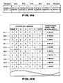
- the R register serves to hold in bit units the status data of each of the pitch designating switches 2a-2g which is scanned by the CPU 6, and has a 7-bit structure as shown in Fig. 3A. As this diagram clearly shows, the status data of each of the switches 2a to 2g are respectively stored in the individual bits 1 (LSB) to 7 (MSB) of the R register. The value of each bit is "1" when its associated switch is ON and "0" when it is OFF (see Fig. 3B).
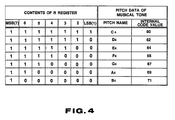
- a single tone conversion table 11 holds the contents of the R register and pitch data (internal code values) of single tones corresponding to these contents as shown in Fig. 4.
- the CPU 6 searches through the single tone conversion table 11 using the content of the R register as a key to acquire the pitch data of a single tone designated by operation of the pitch designating switches 2 in normal mode.
- every bit of the R register becomes “1" and the CPU 6 searches through the single tone conversion table 11 and reads out pitch data (internal code value) "60" (in decimal notation) corresponding to the content of the R register having all the bits set to "1."
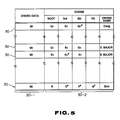
- a first chord conversion table 12 holds chord data 30 consisting of a pair of chord data 30-1 and pitch data 30-2 of each constituent of a chord corresponding to the chord data 30-1 for every chord designated in chord mode 1, as shown in Fig. 5. These data, which will be described later, are associated with a chord set by operating the pitch designating switches 2 and octave setting switches 3 in chord mode 1.
- the CPU 6 searches through the first chord conversion table 12 using the chord data 30-1 as a key and reads out pitch data of the individual constituents of the designated chord.
- the individual constituents of each chord stored in a chord constituent region 30 are indicated by pitch symbols such as "C4" and "E4" in Fig. 5, actually pitch data (internal code values) corresponding to these pitch symbols are stored.
- a second chord conversion table 13 holds pitch data (internal code values) of the individual constituents of every chord designated in chord mode 2, as shown in Fig. 6.
- the pitch data (internal code values) of the individual constituents of a chord designated by operation of the pitch designating switches 2 is stored in the conversion table 13 at an address corresponding to the value of the R register.
- chord mode 2 the CPU 6 searches through the second chord conversion table 13 using the value of the R register holding the status data of each of the pitch designating switches 2 as a key and reads out pitch data (internal code values) of the individual constituents of the chord designated by operation of the switches 2.
- the tone generator 7 has an analog sound source or a digital sound source such as an FM sound source or PCM sound source, and can simultaneously generate a plurality of musical tone signals with different pitches. Based on the pitch data, timbre data, volume data, etc. sent from the CPU 6 in normal mode, the tone generator 7 generates a musical tone signal at the designated pitch with musical characteristics such as the timbre and volume corresponding to the above timbre data and volume data. The tone generator 7 starts generating the musical tone upon reception of key-ON data from the CPU 6, and stops the tone generation upon reception of key-OFF data from the CPU 6. The musical tone signal from the tone generator 7 is sent to a sound or tone output unit 14.
- an analog sound source or a digital sound source such as an FM sound source or PCM sound source
- the CPU 6 searches the single tone conversion table 11 shown in Fig. 4 from the status data of the pitch designating switches 2 stored in the R register to obtain the root of a chord and obtains the type of the chord from the status data of the octave setting switches 3. Based on the root and type of the chord, the CPU 6 prepares pitch data of each constituent of the chord and sends it to the tone generator 7.
- the CPU 6 searches the root and type of a chord from the status data of the pitch designating switches 2 stored in the R register. Based on the status data of the octave setting switches 3 and sharp/flat setting switches 5, the CPU 6 alters the pitches of the individual constituents of the chord and sends the resulting pitch data of each constituent of the chord to the tone generator 7.
- the tone generator 7 Based on the received pitch data of each chord constituent, the tone generator 7 generates the chord and sends it to the tone output unit 14.
- the tone output unit 14 comprises an amplifier 14-1 and a loud speaker 14-2 and produces a single tone or a chord sent from the tone generator 7 outside as a sound.
- Figs. 7A and 7B are outer views of an electronic wind instrument realized by providing various switches illustrated in Fig. 1.
- This embodiment takes the shape of a wind instrument having a horn section 15 and a mouth section 16.
- the pitch designating switches 2 comprising the switches 2a-2g, octave setting switches 3 comprising the switches 3a-3e, timbre/effect select switch 4 and sharp/flat setting switches 5a and 5b, which have been explained referring to Fig. 1, are provided on the horn section 15 where a player can easily put his fingers on.
- the breath sensor 8 shown in Fig. 1 is provided near the joint between the mouth section 16 and the horn section 15.
- Fig. 1 The other elements also shown in Fig. 1 are provided at the interior of the horn section 15 shown in Figs. 7A and 7B.
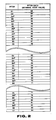
- Figs. 8A through 8F are diagrams for explaining how to play a music in normal mode and chord mode 1.
- Figs. 8C-8F illustrate the statuses of the pitch designating switches 2 and octave setting switches 3, and those switches activated (ON) are marked in black.
- the switches 2a and 2b of the pitch designating switches are switched ON to designate the pitch name of "A” and at the same time the switch 3b of the octave setting switches is switched ON to specify "one octave above.”
- the pitches of "D5 and "G6" are set by performing the switch operations as shown in Figs. 8E and 8F.
- the pitches of "A4" to "G4" are designated by operation of the pitch designating switches 2 and "2 octaves above,” “1 octave above,” “no octave alteration,” “1 octave below” and “2 octaves below” can be specified to those pitches designated by the pitch designating switches 2, by activating the associated switches 3a 3e of the octave setting switches 3.
- a pitch half tone higher than the one set in the above manner can be set by activating the sharp setting switch 5a and a half tone lower pitch can be set by activating the flat setting switch 5b.
- a musical tone (single tone) having the pitch set by operation of the pitch designating switches 2, octave setting switches 3 and sharp/flat setting switches 5 is generated from the tone generator 7 and produced as a sound from the tone output unit 14.
- the pitch of the desired musical tone (single tone) can be set by operating the pitch designating switches 2, octave setting switches 3 and sharp/flat setting switches 5, and the desired melody can be played by performing the above breath operation.
- chord mode 1 should be selected by the mode selecting switch 1.
- chord mode 1 operating the pitch designating switches 2 specifies the roots of chords and operating the octave setting switches 3 specifies the types of chords, such as minor 7th chord, minor chord, major chord, suspended chord, and augmented chord. More specifically, the minor 7th chord, minor chord, major chord, suspended chord, and augmented chord are designated by respectively operating the switches 3a to 3e of the octave setting switches 3.
- chord mode 1 therefore, the root “C4" of the chord is set by operating the pitch designating switches 2 as shown in Fig. 8C and the "major chord" is set by operating the octave setting switch 3C as shown in the same diagram.
- chord of "C (C major)” shown in Fig. 8B is generated from the tone generator 7 and produced as a sound from the tone output unit 14.
- chords "Am (A minor),” “Dm (D minor)” and “"Gm7 (G minor 7th)” as shown in Fig. 8B are set by the operation of the pitch designating switches 2 and octave setting switches 3, and these chords are generated from the tone generator 7 and produced as a sound from the tone output unit 14 by effecting the breath operation.
- chord mode 1 the desired chord can be set by operating the pitch designating switches 2 and octave setting switches 3 and this chord can be played by effecting the breath operation.
- chord mode 2 the octave setting switches 3 will not be operated, and the types of chords (major chord, minor chord, major 7th chord, etc.) and the roots of the chords are set by operating only the pitch designating switches 2. Operating the octave setting switches 3 can set and alter in the units of octaves the pitches of the constituents of each chord set in the above manner.
- the functions of the individual octave setting switches 3 are the same as those in normal mode. That is, the pitch of each constituent of the chord set by the operation of the pitch designating switches 2 can be altered in the units of octaves like "2 octaves above,” “1 octave above,” “no octave alteration,” “1 octave below” and “2 octaves below” by activating the associated switches 3a-3e of the octave setting switches 3.
- chord mode 2 the individual switches 2a-2g of the pitch designating switches are respectively assigned with the pitches "C4" (switch 2g), “D4" (switch 2f), “E4" (switch 2e), “F4" (switch 2d), “G4" (switch 2c), “A4" (switch 2b) and “B4" (switch 2a), as indicated within the parentheses "( )" affixed on the right of the switches in Fig. 9B.
- any two of the pitch designating switches 2 are switched ON. If, at this time, the designated two pitch names are adjacent to each other (having an adjacent pitch relation), the lowest pitch designated will be the root of the minor chord. For instance, when the switch 2g associated with the pitch name "C4" and the switch 2f associated with the pitch name "D4" are switched ON as shown in Fig. 9C, the C minor chord having the lowest pitch "C4" as its root is specified since those two designated pitches "C4" and "D4" have a continuous pitch relation. Since the switch 3d is ON specifying "1 octave below," the C minor chord (Cm) having the pitch "C3" as the root is specified.
- a minor chord having the highest pitch designated as the root is set. For instance, when the switch 2a associated with the pitch name "B4" and the switch 2d associated with the pitch name "F4" are switched ON, with the switch 3c for specifying "no octave alteration" being switched ON as shown in Fig. 9D, "B4" and "F4" have a non-adjacent pitch relation and "B4" is the highest pitch. Accordingly, the B minor chord (Bm) having the highest pitch "B4" (see Fig. 9A) as its root is specified.
- a D minor chord (Dm), E minor chord (Em), F minor chord (Fm) and G minor chord (Gm) other than the aforementioned C minor chord (Cm) and B minor chord (Bm) can be set by operating the pitch designating switches 2 and octave setting switches 3 as shown in Figs. 10B to 10F. That is, it is possible to set minor chords having all the notes of "C,” “D,” “E,” “F,” “G,” “A” and “B” in one octave range as the roots.
- a major 7th chord having the lowest pitch designated as the root is set. For instance, when the switches 2c to 2e are switched ON, with the switch 3b for specifying "1 octave above" being switched ON as shown in Fig. 9E, the E major 7th chord (E7) (see Fig. 9A) having the lowest pitch "E5" (associated with the switch 2c) as its root is specified.
- a major 7th chord having the highest pitch designated as the root is set. For instance, when the switches 2c, 2e and 2f are switched ON, with the switch 3c for specifying "no octave alteration" being switched ON as shown in Fig. 9F, the G major 7th chord (G7) (see Fig. 9A) having the highest pitch "G4" as its root is specified.
- a C major 7th chord (C7), D major 7th chord (D7), F major 7th chord (F7) and A major 7th chord (A7) other than the aforementioned E major 7th chord (E7) and G major 7th chord (G7) can be set by operating the pitch designating switches 2 and octave setting switches 3 as shown in Figs. 11B to 11E. That is, it is possible to set major 7th chords having all the notes of "C,” “D,” “E,” “F,” “G,” “A” and “B” in one octave range as the roots.
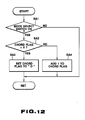
- chord flag used in the flowchart is for storing the presently selected mode; it stores "0" for normal mode, "1" for chord mode 1 and "2" for chord mode 2.
- the CPU 6 discriminates whether or not the mode selecting switch 1 is ON (SA1), then discriminates whether or not the chord flag is set to "2" (SA2) if the switch 1 is ON.
- chord flag is set to "2" (i.e., if the chord mode 2 has been selected), this flag is then set to "0" (SA3).
- chord flag is not set to "2" in SA2, i.e., if it is "0" or "1,” the value of the flag is incremented by 1 (SA4).
- the CPU 6 executes the process of the operational flowchart shown in Fig. 13 based on the chord flag upon occurrence of a timer interrupt at a predetermined cycle.
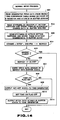
- the statuses (ON/OFF states) of the individual switches 2a-2g of the pitch designating switches 2 are scanned and are stored in the R register shown in Fig. 2A (SB1).
- the statuses of the switches 2a-2g are stored in the first bit (LSB) to seventh bit (MSB) of the R register, respectively.
- the CPU 6 discriminates whether or not the value of the chord flag is "0" (SB2) and executes the normal mode process to generate a musical tone (single tone) at the pitch designated by the operation of the pitch designating switches 2 if the flag is "0" (i.e., if the normal mode has been selected) (SB3).
- the CPU 6 discriminates whether or not the value of the chord flag is "1" (SB4). If the chord flag is "1" (if the chord mode 1 has been selected), the CPU 6 executes the chord mode 1 process to generate a chord whose root is the pitch designated by the operation of the pitch designating switches 2 and which is designated by the operation of the octave setting switches 3 (SB5).
- chord flag is not "1" in SB4, i.e., if it is "2" (chord mode 2 having been selected)
- the CPU 6 executes the chord mode 2 process to generate a chord designated by the operation of the pitch designating switches 2 (SB6).
- Fig. 14 illustrates the operational flowchart for explaining the normal mode process SB3.
- the CPU 6 searches the single tone conversion table 11 shown in Fig. 3 using the value of the R register as a key, reads out the pitch data (internal code value) designated by operation of the pitch designating switches 2 and stores the pitch data in the buffer KENAME (SC1).
- the CPU 6 searches the single tone conversion table 11, reads out pitch data "71" of "B4" (4-th octave of "B") corresponding to the content of the R register and stores the data in the buffer KENAME (see Fig. 4).
- the CPU 6 scans the statuses of the sharp/flat setting switches 5, and it sets "1" in the buffer SHA.FRA if sharp setting switch 5a is ON and sets "-1" therein if the flat setting switch 5b is ON (SC2).
- the CPU 6 scans the statuses of the individual switches 3a-3e of the octave setting switches 3 and stores octave change data corresponding to activated switches in the buffer OCTBF (SC3). For instance, if the switch 3b is ON, octave change data "12" is written in the buffer OCTBF. If the switches 3a, 3c, 3d and 3e are ON, octave change data of "24,” "0,” “-12” and “-24” are respectively written in the buffer 0CTBF.
- the pitch data (internal code value) of the pitch of the same pitch name increases by 12 upon each 1-octave increment and decreases by 12 upon each 1-octave decrement.
- the above operation permits the buffer OCTBF to store values corresponding to pitch differences associated with a command to alter the 4-th octave pitch designated by the operation of the pitch designating switches 2 in the units of octaves designated by the operation of the octave setting switches 3.
- This operation permits the buffer NEWKEY to store the pitch data (internal code value) designated by the pitch designating switches 2, octave setting switches 3 and sharp/flat setting switches 5.
- the CPU 6 then discriminates whether or not the value in the buffer NEWKEY equals the value in buffer OLDKEY (SC5).
- the value in the buffer NEWKEY becomes equal to that in the buffer OLDKEY if the previous operation of the pitch designating switches 2, octave setting switches 3 and sharp/flat setting switches 5 is the same as the present operation thereof. It is therefore discriminated whether or not pitch designation has been changed by determining if the values in the buffers NEWKEY and OLDKEY equals each other.
- the value of the buffer NEWKEY is stored in the buffer OLDKEY (SC6).
- the pitch data stored in the buffer NEWKEY is then written in the buffer KDATA (SC7) and it is discriminated whether or not a tone-ON flag is ON (SC8).
- the tone-ON flag serves to memorize whether a musical tone is presently generated from the tone generator 7; it holds “1" (ON) if the tone generation is in progress and "0" (OFF) if otherwise.
- the CPU 6 If the tone-ON flag is ON in SC8, the CPU 6 outputs a key-OFF signal to the tone generator 7 to specify interruption of the tone generation (SC9) and sets the tone-ON flag to "0" (OFF) (SC10).
- the pitch data stored in the buffer KDATA is then sent to the tone generator 7 (SC11).
- tone generation from the tone generator 7 will be stopped when a musical tone is presently produced therefrom, and newly designated pitch data will be sent to the tone generator 7.
- the tone-ON flag is reset to "0" (OFF) from the "1" (ON) status.
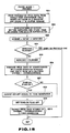
- chord mode 1 process of the aforementioned SB5 referring to the flowchart shown in Fig. 15.
- the CPU 6 searches the single tone conversion table 11 using the value of the R register as a key, and stores the pitch data of the root of the chord designated by operation of the pitch designating switches 2, in the buffer KENAME (SD1).
- the CPU 6 scans the statuses of the octave setting switches 3 and stores the chord type data designated by the operation of the switches 3 into the buffer OCTBF (SD2).
- the values of the chord type data are the same as those of the aforementioned octave change data in normal mode. That is, the value of the chord type data is "24" when the switch 3a is switched ON specifying a minor 7th chord, is "12" when the switch 3b is switched ON specifying a minor chord, and is "0" when the switch 3c is switched ON specifying a major chord. Similarly, the value of the chord type data is "-2" when the switch 3d is switched ON specifying a suspended chord and "-24" when the switch 3e is switched ON specifying an augmented chord.
- the pitch data (internal code value) of the root of a chord stored in the buffer KENAME is added to the designated chord type data stored in the buffer OCTBF, and the result (chord data 30-1) is stored in the buffer NEWCODE (SD3).
- the CPU 6 then discriminates whether or not the chord data 30-1 stored in the buffer NEWCODE equals the chord data 30-1 stored in the buffer OLDCODE (SD4).
- the values of the chord data 30-1 in the buffers NEWCODE AND OLDCODE become equal to each other if the chord previously designated by the operation of the pitch designating switches 2 and octave setting switches 3 is the same as the presently designated chord. It is therefore discriminated whether or not chord designation has been changed by determining if the value of the buffer NEWCODE equals that of the buffer OLDCODE,
- chord data 30-1 stored in the buffer NEWCODE will be written in the buffer OLDCODE (SD5).
- the CPU 6 searches the first chord conversion table 12 shown in Fig. 5 using the chord data 30-1 in the buffer NEWCODE as key data, acquires pitch data of the root, third and fifth (also seventh in case of a minor 7th chord), which are the constituents of a chord corresponding to the chord data 30-1, and writes these pitch data in the buffers CHORD0-CHORD2 (CHORD3) (SD6).
- the CPU 6 searches the first chord conversion table 12 using as a key the chord data 30-1 which is the result of adding the pitch data (pitch data of the root of a chord) stored in the buffer KENAME to the chord type data stored in the buffer OCTBF, and prepares the pitch data of the root, third and fifth (also seventh in case of a minor 7th chord), which are the constituents of the designated chord.
- the value of the chord data 30-1 associated with a C major chord is "60.”
- the first chord conversion table 11 shown in Fig. 5 contains the individual constituents of a C augmented chord as a chord associated with the chord data 30-1 having a value of "36.”
- the CPU 6 discriminates whether or not the tone-ON flag is ON ("1") (SD7), and outputs the key-OFF signal to the tone generator 7 if the flag is ON (SD8). Then, the CPU 6 sets the tone-ON flag OFF ("0") (SD9) and sends the pitch data of the constituents of a chord stored in the buffers CHORD0-CHORD2 (CHORD3) to the tone generator 7 (SD10).
- tone generation from the tone generator 7 is stopped and the pitch data of each constituent of a newly designated chord is sent to the tone generator 7.
- the tone-ON flag is reset to OFF ("0").
- the CPU attains pitch data of each constituent of a chord designated by operation of the pitch designating switches 2, from the second chord conversion table 13 shown in Fig. 6 based on the value of the R register and stores the attained pitch data in the buffers CHORD1(root), CHORD1 (third), CHORD2 (fifth) and CHORD4 (seventh) (SE1).
- the value of the R register is equal to the value of the address at which the pitch data of each corresponding chord constituent stored in the second chord conversion table 13, and this pitch data is acquired by reading pitch data from the second chord conversion table 13 at the address specified by the value of the R register.
- a C major 7th chord is specified as shown in Fig. 3B, and the value of the R register would be "7.”
- pitch data (internal code values) of "C4,” “E4,” “G4" and “B4b” the constituents of the C major 7th chord, are stored at the address 7.
- the CPU 6 scans the statuses of the sharp/flat setting switches 5 (SE2) and discriminates whether or not the sharp setting switch 5a is ON (SE3). If the switch 5a is ON, the CPU 6 increments the values of the buffers CHORD0-CHORD2 (CHORD3) by 1 (SE4). If the switch 5a is OFF in SE3, the CPU 6 then discriminates whether or not the flat setting switch 5b is ON (SE5) and decrements the values of the buffers CHORD0-CHORD2 (CHORD3) by 1 (SE6).
- the CPU 6 scans the statuses of the individual octave setting switches 3 and alters the pitch data stored in the buffers CHORD0-CHORD2 (CHORD3) in the units of octaves in accordance with the octave setting switches 3a-3e switched OFF. More specifically, if the switch 3a is ON, the values of the buffers CHORD0-CHORD2 (CHORD3) are all incremented by "24" (2-octave increment), and if the switch 3b is ON, the values of the buffers CHORD0-CHORD2 (CHORD3) are all incremented by "12" (1-octave increment).
- the pitches of the individual constituents of the chord designated by the operation of the pitch designating switches 2 are altered in the units of octaves by operating the octave setting switches 3.
- the CPU 6 discriminates whether or not the values of the buffers CHORD0-CHORD2 (CHORD3) equal those of OLDCHORD0-OLDCHORD2 (OLDCHORD3) (SE8).
- OLDCHORD0-OLDCHORD2 (OLDCHORD3) contain pitch data of the constituents of the previously designated chord (which will be described later).
- octave setting switches 3 and sharp/flat setting switches 5 When the present chord designation done by operating the pitch designating switches 2, octave setting switches 3 and sharp/flat setting switches 5 is the same as the previous one, the values of the buffers CHORD0-CHORD2 (CHORD3) respectively coincide with those of the buffers OLDCHORD0-OLDCHORD2 (OLDCHORD3). Accordingly, it is discriminated in the aforementioned SE8 whether or not chord designation has been changed.
- the tone-ON flag is ON, i.e., if a musical tone is presently generated from the tone generator 7, the key-OFF signal is sent to the tone generator 7 (SE11) and the tone-ON flag is set OFF ("0") (SE12). Subsequently, the pitch data stored in the buffers CHORD0-CHORD2 (CHORD3) are sent to the tone generator 7.
- tone generation is stopped and the pitch data of the individual constituents of a newly designated chord is sent to the tone generator 7.
- a single tone of the pitch selected from the range of "B1" to "C7" shown in Fig. 2 can be set by operating the pitch designating switches 2, octave setting switches 3 and sharp/flat setting switches 5.
- chord mode 1 Five types of chords, "minor 7th chord,” “minor chord,” “major chord,” “suspended chord” and “augmented chord” having each the full scale notes of 1 octave can be set as the root by operating the pitch designating switches 2 and octave setting switches 3.
- chord mode 2 three types of chords, "major chord,” “minor chord” and “major 7th chord” having each the full scale notes of 1 octave can be set at the root by operating the pitch designating switches 2, octave setting switches 3 and sharp/flat setting switches 5.
- the single tone or chord set in the above manner can be generated from the tone generator 7 by performing a breath operation on the mouth section 15 at a strength equal to or greater than a predetermined level.
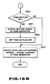
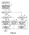
- Fig. 17 illustrates the operation flowchart of the tone generation control process the CPU 6 executes when a breath operation is performed.
- the CPU 6 When a timer interrupt occurs at a predetermined cycle, the CPU 6 reads breath data corresponding to the breath operation through the A/D converter 10, and writes this data into the BRATH register (not shown) (SF1).
- the CPU 6 discriminates whether or not the value in the BRATH register is equal to or greater than a threshold value Th at the start of generation of the key-ON signal (SF2). If it is equal to or greater than the threshold value Th, the CPU 6 discriminates whether or not the tone-ON flag is ON ("1") (SF3). If the tone-ON flag is not ON, i.e., if no tone generation is presently done by the tone generator 7, the key-ON signal and initial data specifying the volume, etc. at the start of tone generation are sent to the tone generator 7 (SF4), and the tone-ON flag is set ON ("1") (SF5).
- the initial data is set based on the amount of a change in breath data per unit time, for example.
- the tone generator 7 Upon reception of the key-ON signal through the above operation, the tone generator 7 starts generating a chord or a single tone based on the pitch data of each constituent of the chord or the pitch data of the single tone sent from the CPU 6.
- the CPU 6 prepares after data such as volume data for specifying the volume of a presently generated chord (or single tone) based on the value of the breath data (SF6).
- the volume of the chord or single tone to be generated will be changed in accordance with the strength of the breath operation.
- the CPU 6 discriminates whether or not the tone-ON flag is ON ("1"(SF7). If this flag is ON ("1"), the CPU 6 sends the key-OFF signal to the tone generator 7 (SF8) and then sets the flag OFF ("0") (SF9).
- the key-OFF data is sent to the tone generator 7, causing the generator 7 to stop the chord or single tone generation.
- the number of the pitch designating switches switched ON is 1, 2 or 3 in chord mode 2, the major chord, minor chord or seventh chord is set, it is also possible to set other chords associated with the number of operated switches when it is 4 or more.
- the association between the number of activated switches and the types of chords to be set by the switches need not be limited, but may hold an arbitrary relation.
- the number of the pitch designating switches is in no way restricted to 7; it can vary as long as the switches can designate pitches in at least a 1-octave range. Further, the root of a chord need not be restricted to fall within the range specified in the above embodiment.
- the CPU may prepare pitch data of each constituent of a chord through a computation without using any chord conversion table.
- pitch designating switches are not restricted to be of an ON/OFF type, but may be electrostatic capacitive or pressure-sensitive switches.
- this invention can realize a chord setting apparatus particularly effective in an electronic wind instrument, which has fewer number of pitch designating switches and normally designates a pitch by a combination of operated pitch designating switches, and an electronic wind instrument which facilitates the setting of a chord using this chord setting apparatus.
Landscapes
- Physics & Mathematics (AREA)
- Engineering & Computer Science (AREA)
- Acoustics & Sound (AREA)
- Multimedia (AREA)
- Electrophonic Musical Instruments (AREA)
Applications Claiming Priority (4)
| Application Number | Priority Date | Filing Date | Title |
|---|---|---|---|
| JP80183/88 | 1988-06-17 | ||
| JP8018388 | 1988-06-17 | ||
| JP305722/88 | 1988-12-02 | ||
| JP63305722A JP2591121B2 (ja) | 1988-06-17 | 1988-12-02 | 和音設定装置及び電子管楽器 |
Publications (3)
| Publication Number | Publication Date |
|---|---|
| EP0346940A2 true EP0346940A2 (fr) | 1989-12-20 |
| EP0346940A3 EP0346940A3 (en) | 1990-02-28 |
| EP0346940B1 EP0346940B1 (fr) | 1993-09-15 |
Family
ID=26421245
Family Applications (1)
| Application Number | Title | Priority Date | Filing Date |
|---|---|---|---|
| EP89111123A Expired - Lifetime EP0346940B1 (fr) | 1988-06-17 | 1989-06-19 | Dispositif pour établir des accords et instrument à vent électronique utilisant ce dispositif |
Country Status (5)
| Country | Link |
|---|---|
| US (1) | US5014586A (fr) |
| EP (1) | EP0346940B1 (fr) |
| JP (1) | JP2591121B2 (fr) |
| KR (1) | KR930005219B1 (fr) |
| DE (1) | DE68909119T2 (fr) |
Families Citing this family (9)
| Publication number | Priority date | Publication date | Assignee | Title |
|---|---|---|---|---|
| US5403966A (en) * | 1989-01-04 | 1995-04-04 | Yamaha Corporation | Electronic musical instrument with tone generation control |
| JP2775793B2 (ja) * | 1989-01-06 | 1998-07-16 | ヤマハ株式会社 | 電子管楽器 |
| US5446238A (en) | 1990-06-08 | 1995-08-29 | Yamaha Corporation | Voice processor |
| US5461189A (en) * | 1990-07-06 | 1995-10-24 | Yamaha Corporation | Waveguide electronic musical instrument employing pre-performance tuning |
| US5278348A (en) * | 1991-02-01 | 1994-01-11 | Kawai Musical Inst. Mfg. Co., Ltd. | Musical-factor data and processing a chord for use in an electronical musical instrument |
| KR940003126B1 (ko) * | 1991-11-15 | 1994-04-13 | 주식회사 금성사 | 전자악기의 코드 처리방법과 장치 |
| JP3013648B2 (ja) * | 1993-03-23 | 2000-02-28 | ヤマハ株式会社 | 自動編曲装置 |
| US7723605B2 (en) | 2006-03-28 | 2010-05-25 | Bruce Gremo | Flute controller driven dynamic synthesis system |
| US20190172434A1 (en) * | 2017-12-04 | 2019-06-06 | Gary S. Pogoda | Piano Key Press Processor |
Family Cites Families (23)
| Publication number | Priority date | Publication date | Assignee | Title |
|---|---|---|---|---|
| US2138500A (en) * | 1936-10-28 | 1938-11-29 | Miessner Inventions Inc | Apparatus for the production of music |
| US2301184A (en) * | 1941-01-23 | 1942-11-10 | Leo F J Arnold | Electrical clarinet |
| US3439106A (en) * | 1965-01-04 | 1969-04-15 | Gen Electric | Volume control apparatus for a singletone electronic musical instrument |
| US3429976A (en) * | 1966-05-11 | 1969-02-25 | Electro Voice | Electrical woodwind musical instrument having electronically produced sounds for accompaniment |
| US3767833A (en) * | 1971-10-05 | 1973-10-23 | Computone Inc | Electronic musical instrument |
| US3938419A (en) * | 1974-05-20 | 1976-02-17 | David De Rosa | Electronic musical instrument |
| US4065993A (en) * | 1974-12-26 | 1978-01-03 | Nippon Gakki Seizo Kabushiki Kaisha | Electronic organ with a three-finger chord and one-finger automatic chord playing mode selector |
| DE2523623C3 (de) * | 1975-05-28 | 1981-10-15 | Naumann, Klaus, 8013 Haar | Elektronisches Musikinstrument |
| DE2535344C2 (de) * | 1975-08-07 | 1985-10-03 | CMB Colonia Management- und Beratungsgesellschaft mbH & Co KG, 5000 Köln | Einrichtung zum elektronischen Erzeugen von Klangsignalen |
| US4178821A (en) * | 1976-07-14 | 1979-12-18 | M. Morell Packaging Co., Inc. | Control system for an electronic music synthesizer |
| US4168645A (en) * | 1977-05-20 | 1979-09-25 | Morris B. Squire | Electronic musical instrument |
| US4274321A (en) * | 1979-07-30 | 1981-06-23 | Jerome Swartz | Harmony authorization detector synthesizer |
| US4353278A (en) * | 1980-01-28 | 1982-10-12 | Nippon Gakki Seizo Kabushiki Kaisha | Chord generating apparatus of electronic musical instrument |
| JPS56153388A (en) * | 1980-04-30 | 1981-11-27 | Matsushita Electric Industrial Co Ltd | Electronic musical instrument |
| DE3023578C2 (de) * | 1980-06-24 | 1983-08-04 | Matth. Hohner Ag, 7218 Trossingen | Schaltungsanordnung zum Identifizieren des Akkordtyps und seines Grundtons bei einem chromatisch gestimmten elektronischen Musikinstrument |
| GB2083669B (en) * | 1980-09-05 | 1985-01-03 | Casio Computer Co Ltd | Key data entry system |
| JPS5773799A (en) * | 1980-10-28 | 1982-05-08 | Nippon Musical Instruments Mfg | Electronic musical instrument |
| US4418599A (en) * | 1982-04-08 | 1983-12-06 | Raskin Gregory D | Electronic signal level control apparatus for acoustical-electrical transducer instrument |
| US4757737A (en) * | 1986-03-27 | 1988-07-19 | Ugo Conti | Whistle synthesizer |
| JPS63128596A (ja) * | 1986-11-17 | 1988-06-01 | 富士通株式会社 | エレクトロルミネツセンスパネル |
| JPS63210893A (ja) * | 1987-02-27 | 1988-09-01 | 株式会社 コムニクス | 電子弦楽器の入力装置 |
| US4915008A (en) * | 1987-10-14 | 1990-04-10 | Casio Computer Co., Ltd. | Air flow response type electronic musical instrument |
| US4919032A (en) * | 1987-12-28 | 1990-04-24 | Casio Computer Co., Ltd. | Electronic instrument with a pitch data delay function |
-
1988
- 1988-12-02 JP JP63305722A patent/JP2591121B2/ja not_active Expired - Fee Related
-
1989
- 1989-06-09 US US07/364,010 patent/US5014586A/en not_active Expired - Lifetime
- 1989-06-15 KR KR1019890008279A patent/KR930005219B1/ko not_active Expired - Fee Related
- 1989-06-19 EP EP89111123A patent/EP0346940B1/fr not_active Expired - Lifetime
- 1989-06-19 DE DE89111123T patent/DE68909119T2/de not_active Expired - Fee Related
Also Published As
| Publication number | Publication date |
|---|---|
| DE68909119T2 (de) | 1994-02-17 |
| DE68909119D1 (de) | 1993-10-21 |
| JPH0277095A (ja) | 1990-03-16 |
| EP0346940B1 (fr) | 1993-09-15 |
| KR930005219B1 (ko) | 1993-06-16 |
| US5014586A (en) | 1991-05-14 |
| EP0346940A3 (en) | 1990-02-28 |
| JP2591121B2 (ja) | 1997-03-19 |
| KR900000833A (ko) | 1990-01-30 |
Similar Documents
| Publication | Publication Date | Title |
|---|---|---|
| US5619003A (en) | Electronic musical instrument dynamically responding to varying chord and scale input information | |
| EP0486925B1 (fr) | Instrument de musique électronique | |
| EP0346940B1 (fr) | Dispositif pour établir des accords et instrument à vent électronique utilisant ce dispositif | |
| JPH07261762A (ja) | 自動伴奏情報発生装置 | |
| JPH0713036Y2 (ja) | 電子鍵盤楽器 | |
| US5585586A (en) | Tempo setting apparatus and parameter setting apparatus for electronic musical instrument | |
| JP2543307Y2 (ja) | 電子楽器 | |
| JPH06259070A (ja) | 電子楽器 | |
| US5418324A (en) | Auto-play apparatus for generation of accompaniment tones with a controllable tone-up level | |
| KR970000428Y1 (ko) | 코러스 기능이 구비된 컴퓨터 반주기 | |
| JP2580746Y2 (ja) | 電子管楽器 | |
| JP2596303B2 (ja) | 電子楽器 | |
| JPH08185174A (ja) | 音声発生装置 | |
| JPH05204297A (ja) | 階名発生装置 | |
| JP2001051681A (ja) | 自動伴奏情報発生装置 | |
| JP2699745B2 (ja) | 電子楽器 | |
| JP3030940B2 (ja) | 楽音制御装置 | |
| JP2694788B2 (ja) | 電子楽器 | |
| JP3277662B2 (ja) | 楽音発生装置 | |
| JP3082294B2 (ja) | 伴奏音信号形成装置 | |
| JP3282254B2 (ja) | 楽音発生装置 | |
| JPH09198048A (ja) | チューニング装置 | |
| JPH07152374A (ja) | 電子楽器 | |
| JPH05265458A (ja) | 電子楽器 | |
| JPH08160945A (ja) | 楽音制御装置 |
Legal Events
| Date | Code | Title | Description |
|---|---|---|---|
| PUAI | Public reference made under article 153(3) epc to a published international application that has entered the european phase |
Free format text: ORIGINAL CODE: 0009012 |
|
| AK | Designated contracting states |
Kind code of ref document: A2 Designated state(s): DE FR GB IT |
|
| PUAL | Search report despatched |
Free format text: ORIGINAL CODE: 0009013 |
|
| AK | Designated contracting states |
Kind code of ref document: A3 Designated state(s): DE FR GB IT |
|
| 17P | Request for examination filed |
Effective date: 19900625 |
|
| 17Q | First examination report despatched |
Effective date: 19910808 |
|
| GRAA | (expected) grant |
Free format text: ORIGINAL CODE: 0009210 |
|
| AK | Designated contracting states |
Kind code of ref document: B1 Designated state(s): DE FR GB IT |
|
| REF | Corresponds to: |
Ref document number: 68909119 Country of ref document: DE Date of ref document: 19931021 |
|
| ITF | It: translation for a ep patent filed | ||
| ET | Fr: translation filed | ||
| PLBE | No opposition filed within time limit |
Free format text: ORIGINAL CODE: 0009261 |
|
| STAA | Information on the status of an ep patent application or granted ep patent |
Free format text: STATUS: NO OPPOSITION FILED WITHIN TIME LIMIT |
|
| 26N | No opposition filed | ||
| PGFP | Annual fee paid to national office [announced via postgrant information from national office to epo] |
Ref country code: FR Payment date: 19970610 Year of fee payment: 9 |
|
| PGFP | Annual fee paid to national office [announced via postgrant information from national office to epo] |
Ref country code: GB Payment date: 19980610 Year of fee payment: 10 |
|
| PGFP | Annual fee paid to national office [announced via postgrant information from national office to epo] |
Ref country code: DE Payment date: 19980629 Year of fee payment: 10 |
|
| PG25 | Lapsed in a contracting state [announced via postgrant information from national office to epo] |
Ref country code: FR Free format text: LAPSE BECAUSE OF NON-PAYMENT OF DUE FEES Effective date: 19990226 |
|
| REG | Reference to a national code |
Ref country code: FR Ref legal event code: ST |
|
| PG25 | Lapsed in a contracting state [announced via postgrant information from national office to epo] |
Ref country code: GB Free format text: LAPSE BECAUSE OF NON-PAYMENT OF DUE FEES Effective date: 19990619 |
|
| GBPC | Gb: european patent ceased through non-payment of renewal fee |
Effective date: 19990619 |
|
| PG25 | Lapsed in a contracting state [announced via postgrant information from national office to epo] |
Ref country code: DE Free format text: LAPSE BECAUSE OF NON-PAYMENT OF DUE FEES Effective date: 20000503 |
|
| PG25 | Lapsed in a contracting state [announced via postgrant information from national office to epo] |
Ref country code: IT Free format text: LAPSE BECAUSE OF NON-PAYMENT OF DUE FEES;WARNING: LAPSES OF ITALIAN PATENTS WITH EFFECTIVE DATE BEFORE 2007 MAY HAVE OCCURRED AT ANY TIME BEFORE 2007. THE CORRECT EFFECTIVE DATE MAY BE DIFFERENT FROM THE ONE RECORDED. Effective date: 20050619 |