EP0346797A2 - Moteur à deux temps avec un carburateur - Google Patents
Moteur à deux temps avec un carburateur Download PDFInfo
- Publication number
- EP0346797A2 EP0346797A2 EP89110592A EP89110592A EP0346797A2 EP 0346797 A2 EP0346797 A2 EP 0346797A2 EP 89110592 A EP89110592 A EP 89110592A EP 89110592 A EP89110592 A EP 89110592A EP 0346797 A2 EP0346797 A2 EP 0346797A2
- Authority
- EP
- European Patent Office
- Prior art keywords
- combustion engine
- inlet
- internal combustion
- additional
- channel
- Prior art date
- Legal status (The legal status is an assumption and is not a legal conclusion. Google has not performed a legal analysis and makes no representation as to the accuracy of the status listed.)
- Withdrawn
Links
Images

Classifications
-
- F—MECHANICAL ENGINEERING; LIGHTING; HEATING; WEAPONS; BLASTING
- F02—COMBUSTION ENGINES; HOT-GAS OR COMBUSTION-PRODUCT ENGINE PLANTS
- F02M—SUPPLYING COMBUSTION ENGINES IN GENERAL WITH COMBUSTIBLE MIXTURES OR CONSTITUENTS THEREOF
- F02M3/00—Idling devices for carburettors
- F02M3/08—Other details of idling devices
- F02M3/12—Passageway systems
-
- F—MECHANICAL ENGINEERING; LIGHTING; HEATING; WEAPONS; BLASTING
- F02—COMBUSTION ENGINES; HOT-GAS OR COMBUSTION-PRODUCT ENGINE PLANTS
- F02B—INTERNAL-COMBUSTION PISTON ENGINES; COMBUSTION ENGINES IN GENERAL
- F02B25/00—Engines characterised by using fresh charge for scavenging cylinders
-
- F—MECHANICAL ENGINEERING; LIGHTING; HEATING; WEAPONS; BLASTING
- F02—COMBUSTION ENGINES; HOT-GAS OR COMBUSTION-PRODUCT ENGINE PLANTS
- F02B—INTERNAL-COMBUSTION PISTON ENGINES; COMBUSTION ENGINES IN GENERAL
- F02B75/00—Other engines
- F02B75/02—Engines characterised by their cycles, e.g. six-stroke
- F02B2075/022—Engines characterised by their cycles, e.g. six-stroke having less than six strokes per cycle
- F02B2075/025—Engines characterised by their cycles, e.g. six-stroke having less than six strokes per cycle two
Definitions
- the invention relates to a two-stroke internal combustion engine with a carburetor with a gasification part (Venturi), a suction part upstream of the gasification part, a throttle valve part, an output channel downstream of the throttle valve part, a main and a part-load nozzle chamber and a pressurizable fuel supply line, a cylinder with an inlet channel with a Inlet slot, wherein the inlet duct formed in the intake flange is connected to the outlet duct of the carburetor.
- Venturi gasification part
- suction part upstream of the gasification part a throttle valve part
- an output channel downstream of the throttle valve part a main and a part-load nozzle chamber and a pressurizable fuel supply line
- a cylinder with an inlet channel with a Inlet slot wherein the inlet duct formed in the intake flange is connected to the outlet duct of the carburetor.
- Such internal combustion engines have long been known in all areas of application and in particular for use in motor chain saws.
- it is necessary to supply it with air and fuel in a certain air ratio for each operating point given by speed and load.
- the task of the carburetor is to allocate the correct amount of fuel to the intake air and to carry out the measurement of the amount of the mixture of air and fuel necessary for setting the operating point.
- This preparation and supply of the internal combustion engine with a corresponding fuel-air mixture can usually be carried out without problems during operation of the internal combustion engine.
- Two-stroke engines which are supplied with a fuel-air mixture from the carburetor via long intake ducts for thermal or vibration-related reasons, generally suffer from thermal and position-related idling sensitivity, which can lead to fluctuations in engine speed when idling and to engine stall.
- This effect is caused by condensation, puddling due to too large a surface and, at the same time, a lack of air speed in the intake duct of the engine when idling
- a two-stroke internal combustion engine with a gasification part (Venturi), an intake part upstream of the gasification part, a throttle valve part, an outlet duct downstream of the throttle valve part, a main and a part-load nozzle chamber and a pressurizable fuel supply line, a cylinder arranged on a crank chamber with a Inlet duct with an inlet slot, the inlet duct formed in the intake flange being connected to the outlet duct of the carburetor, proposed that the fuel-air mixture can be supplied to the crank chamber through an additional idling duct.
- Venturi gasification part
- the fuel-air mixture is drawn in through the additional idling duct when idling.
- the additional idling duct is controlled by the piston skirt and is opened before the actual inlet duct, so that there is predominantly a vacuum in the additional idling duct.
- the idle channel consists of an additional inlet slot with an upstream channel arranged below the actual inlet slot, i.e. closer to the crankcase.
- the additional idling duct be arranged differently and / or controlled differently, for example by a valve, such as e.g. a diaphragm valve or a flutter valve, which ensures predominant vacuum operation in the idle channel and allows a connection directly to the crank chamber.
- a valve such as e.g. a diaphragm valve or a flutter valve, which ensures predominant vacuum operation in the idle channel and allows a connection directly to the crank chamber.
- the performance characteristics of the internal combustion engine are not influenced, and high air velocities are generated when idling, that the idling duct is designed to be very narrow, a design to 1/10 of the intake time cross section being recommended.
- the fuel-air mixture is drawn in directly at the carburetor in idle mode, in which case an annular slot is formed between the carburetor and the intake flange.
- the idle fuel is introduced directly from the part-load nozzle chamber into the additional idle channel, the air being sucked in from the area between the air filter and the throttle valve.
- the design of the idling system in this way leads to various advantages, namely no position sensitivity, low temperature sensitivity and, due to the small cross section of the additional idling duct, a small condensation surface and a high air speed at the same time. This improves starting behavior and stabilizes idling. At the same time, the acceleration behavior is improved since a relatively "rich idling mixture" can be used.
- the idling speed can be reduced overall.
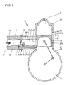
- the internal combustion engine shown only in principle in the figures is designated by 10 and consists of a carburetor 11, which is arranged on an intake flange 20 of a cylinder 30.
- a gasification part (venturi) 12 is formed, into which the air flows in through the intake part 13 and the flow through which the throttle valve part 14 arranged in the gasification part 12 downstream can be regulated.
- the carburetor has the outlet channel 15 behind the throttle valve part 14.
- the partial load is in the region of the throttle valve part 14 formed nozzle chamber 16 which is connected to a control chamber, not shown.
- the housing 18 of the carburetor 11 is connected in the region of the outlet channel 15 to the intake flange 20, in which the inlet channel known per se is formed, which feeds the fuel-air mixture formed in the carburetor 11 to the inlet slot 22 in the cylinder 30, from which it flows flows into the crank chamber 34, is supplied to the combustion chamber 31 via overflow channels, not shown, and after compression by the piston 32, which consists of the piston crown 32a and the piston skirt 32b, and subsequent ignition, flows out via the outlet slot 34.
- the cylinder 30 is on a conventional one Crankcase 33 arranged.
- an additional idle channel 23 is formed in the intake flange 20 parallel to the inlet channel 21, the inlet slot 24 of which is arranged on the inside of the cylinder below the inlet slot 22 of the inlet channel 21.
- the inlet part 25 of the additional idle channel 23 is arranged directly on the carburetor 11, specifically in the transition area from Carburetor 11 to the intake flange 20.
- the inlet part 25 is designed as an annular slot 26, the extent of which comprises approximately a semicircle of the circular cross section of the inlet channel 21.
- the fuel-air mixture which arises in the region of the part-load nozzle chamber in the throttle valve part 14 is drawn in at idle by the inlet part 25 of the additional idle duct 23, as is indicated by the arrow denoted by X in the drawing. From here it is fed to the crank chamber 34 via the additional idling channel 23.
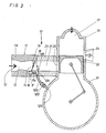
- FIGS. 2, 3 and 4 have essentially the same basic structure as the arrangement described above.
- the additional idling duct 123 connects the transition region of the carburetor 11 to the intake flange 20 directly with the crank chamber 34.
- the inlet part 125 of the additional idling duct 123 is arranged directly on the carburetor and is designed as an annular slot 126, the expansion of which is approximately comprises a semicircle of the circular cross section of the inlet duct 21.
- the outflow slot 124 is suitably arranged for the inflow of the fuel-air mixture into the crank chamber 34, and a check valve 127 is arranged in the course of the additional idling channel 123, so that the idle-fuel-air mixture can be fed in smoothly during operation of the internal combustion engine is feasible.
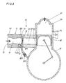
- the additional idle channel 223 is also arranged to open into the crank chamber 34 via an outflow slot 224, a check valve 225 which can be regulated through flow being arranged in the course of the additional idle channel 223.
- the inlet part 225 of the additional idling channel 223 is arranged directly in the carburetor 11 behind the outlet nozzles of the part-load nozzle chamber 16 in front of the throttle valve 19.
- the fuel is supplied via an additional idle fuel supply line 114, which connects the additional idle channel 223 directly to the part-load nozzle chamber 16.
- the inlet 325 of the additional idling duct 223 is likewise arranged directly in the carburetor behind the nozzles of the part-load nozzle chamber 16 and in front of the throttle valve 19.
- An additional idle fuel line 314 is also provided, which connects the part-load nozzle chamber 16 to the additional idle duct 323.
- the idle channel 323 is formed parallel to the inlet channel 21 in the intake flange 20, the inlet slot 324 of which is arranged on the inside of the cylinder below the inlet slot 22 of the inlet channel 21.
Landscapes
- Engineering & Computer Science (AREA)
- Chemical & Material Sciences (AREA)
- Combustion & Propulsion (AREA)
- Mechanical Engineering (AREA)
- General Engineering & Computer Science (AREA)
- Control Of The Air-Fuel Ratio Of Carburetors (AREA)
- Control Of Throttle Valves Provided In The Intake System Or In The Exhaust System (AREA)
Applications Claiming Priority (2)
| Application Number | Priority Date | Filing Date | Title |
|---|---|---|---|
| DE3819971 | 1988-06-11 | ||
| DE19883819971 DE3819971A1 (de) | 1988-06-11 | 1988-06-11 | Zweitakt-brennkraftmaschine mit einem vergaser |
Publications (2)
| Publication Number | Publication Date |
|---|---|
| EP0346797A2 true EP0346797A2 (fr) | 1989-12-20 |
| EP0346797A3 EP0346797A3 (fr) | 1990-05-09 |
Family
ID=6356378
Family Applications (1)
| Application Number | Title | Priority Date | Filing Date |
|---|---|---|---|
| EP89110592A Withdrawn EP0346797A3 (fr) | 1988-06-11 | 1989-06-12 | Moteur à deux temps avec un carburateur |
Country Status (2)
| Country | Link |
|---|---|
| EP (1) | EP0346797A3 (fr) |
| DE (1) | DE3819971A1 (fr) |
Citations (11)
| Publication number | Priority date | Publication date | Assignee | Title |
|---|---|---|---|---|
| GB559771A (en) * | 1943-01-18 | 1944-03-03 | Morris Motors Ltd | Improvements relating to two-stroke internal combustion engines |
| US2388331A (en) * | 1943-04-14 | 1945-11-06 | Metal Products Corp | Fuel supply for two-cycle, crankcase compression engines |
| US2759716A (en) * | 1954-01-21 | 1956-08-21 | Acf Ind Inc | Idling system for two-cycle engines |
| DE1046395B (de) * | 1956-03-10 | 1958-12-11 | Auto Union Gmbh | Leerlaufbetrieb von Zweitakt-Brennkraftmaschinen |
| CH367002A (de) * | 1956-05-23 | 1963-01-31 | Auto Union Gmbh | Zweitakt-Brennkraftmaschine |
| DE1804339A1 (de) * | 1968-10-22 | 1970-05-21 | Audi Nsu Auto Union Ag | Vergaseranlage fuer Brennkraftmaschinen |
| US4159012A (en) * | 1977-06-13 | 1979-06-26 | Textron Inc. | Diaphragm type carburetor for a two-stroke cycle engine |
| GB2088477A (en) * | 1980-12-29 | 1982-06-09 | Brunswick Corp | Idle fuel system for a two-cycle engine |
| GB2125480A (en) * | 1982-08-09 | 1984-03-07 | Outboard Marine Corp | Fuel system for a crankcase compression two-stroke |
| JPS59180026A (ja) * | 1983-03-31 | 1984-10-12 | Suzuki Motor Co Ltd | 2サイクル内燃機関の吸気装置 |
| JPS6043122A (ja) * | 1983-08-18 | 1985-03-07 | Kubota Ltd | 2サイクルエンジンの燃料供給装置 |
-
1988
- 1988-06-11 DE DE19883819971 patent/DE3819971A1/de not_active Withdrawn
-
1989
- 1989-06-12 EP EP89110592A patent/EP0346797A3/fr not_active Withdrawn
Patent Citations (11)
| Publication number | Priority date | Publication date | Assignee | Title |
|---|---|---|---|---|
| GB559771A (en) * | 1943-01-18 | 1944-03-03 | Morris Motors Ltd | Improvements relating to two-stroke internal combustion engines |
| US2388331A (en) * | 1943-04-14 | 1945-11-06 | Metal Products Corp | Fuel supply for two-cycle, crankcase compression engines |
| US2759716A (en) * | 1954-01-21 | 1956-08-21 | Acf Ind Inc | Idling system for two-cycle engines |
| DE1046395B (de) * | 1956-03-10 | 1958-12-11 | Auto Union Gmbh | Leerlaufbetrieb von Zweitakt-Brennkraftmaschinen |
| CH367002A (de) * | 1956-05-23 | 1963-01-31 | Auto Union Gmbh | Zweitakt-Brennkraftmaschine |
| DE1804339A1 (de) * | 1968-10-22 | 1970-05-21 | Audi Nsu Auto Union Ag | Vergaseranlage fuer Brennkraftmaschinen |
| US4159012A (en) * | 1977-06-13 | 1979-06-26 | Textron Inc. | Diaphragm type carburetor for a two-stroke cycle engine |
| GB2088477A (en) * | 1980-12-29 | 1982-06-09 | Brunswick Corp | Idle fuel system for a two-cycle engine |
| GB2125480A (en) * | 1982-08-09 | 1984-03-07 | Outboard Marine Corp | Fuel system for a crankcase compression two-stroke |
| JPS59180026A (ja) * | 1983-03-31 | 1984-10-12 | Suzuki Motor Co Ltd | 2サイクル内燃機関の吸気装置 |
| JPS6043122A (ja) * | 1983-08-18 | 1985-03-07 | Kubota Ltd | 2サイクルエンジンの燃料供給装置 |
Non-Patent Citations (2)
| Title |
|---|
| PATENT ABSTRACTS OF JAPAN vol. 9, no. 172 (M-397)(1895) 17 Juli 1985; & JP-A-60 043 122 (KUBOTA TEKKO) 07 März 1985 * |
| PATENT ABSTRACTS OF JAPAN vol. 9, no. 38 (M-358)(1761) 19 Februar 1985; & JP-A-59 180 026 (SUZUKI) 12 Oktober 1984 * |
Also Published As
| Publication number | Publication date |
|---|---|
| DE3819971A1 (de) | 1989-12-14 |
| EP0346797A3 (fr) | 1990-05-09 |
Similar Documents
| Publication | Publication Date | Title |
|---|---|---|
| DE60009266T2 (de) | Zylinder für eine brennkraftmaschine | |
| DE3624899C2 (fr) | ||
| DE2120949A1 (de) | Vorrichtung zum Verbinden von Schwingungen eines mehrzylindrigen, über Zündkerzen gezündeten Verbrennungsmotors | |
| DE2609082C2 (de) | Vergaser für Verbrennungsmotoren | |
| DE3823525A1 (de) | Vergaser fuer verbrennungsmotoren | |
| AT4966U1 (de) | Viertakt-brennkraftmaschine mit zumindest zwei einlassventilen | |
| DE19939898A1 (de) | Kraftstoff-Luft-Zuführeinrichtung für eine Brennkraftmaschine | |
| DE2211698A1 (de) | Vergaser mit Verzogerungskreis | |
| DE3024181A1 (de) | Rotor-vergasereinrichtung mit leerlauf-gemischbildung fuer brennkraftmaschinen | |
| DE4416693A1 (de) | Vergaser | |
| DE2060612A1 (de) | Vergaser | |
| DE2448819A1 (de) | Brennkraftmaschine | |
| DE2452342C3 (de) | Vergaser für Verbrennungsmotoren | |
| EP0346797A2 (fr) | Moteur à deux temps avec un carburateur | |
| DE2411698A1 (de) | Viertakt-kreiskolben-brennkraftmaschine | |
| DE949913C (de) | Vergaser fuer Verbrennungsmotoren | |
| DE602004005062T2 (de) | Vergaser | |
| DE3243702A1 (de) | Vergaser-verbindungsrohr fuer brennkraftmaschinen | |
| DE3314206C2 (de) | Veränderbarer Venturivergaser | |
| DE2601605C3 (de) | Fallstromvergaser mit Beschleunigungspumpe für Brennkraftmaschinen | |
| WO1985003741A1 (fr) | Installation d'amenee d'air additionnel pour carburateurs de moteurs a combustion interne | |
| DE2440354A1 (de) | Zweitakt-ottomotor | |
| DE1576442A1 (de) | Zusatzgeraet zu Vergasermotoren | |
| DE3215605C1 (de) | Vergaser für Brennkraftmaschinen | |
| DE2607355A1 (de) | Vergaser fuer brennkraftmaschinen |
Legal Events
| Date | Code | Title | Description |
|---|---|---|---|
| PUAI | Public reference made under article 153(3) epc to a published international application that has entered the european phase |
Free format text: ORIGINAL CODE: 0009012 |
|
| AK | Designated contracting states |
Kind code of ref document: A2 Designated state(s): AT BE CH DE ES FR GB GR IT LI LU NL SE |
|
| RBV | Designated contracting states (corrected) |
Designated state(s): DE FR GB IT SE |
|
| PUAL | Search report despatched |
Free format text: ORIGINAL CODE: 0009013 |
|
| AK | Designated contracting states |
Kind code of ref document: A3 Designated state(s): DE FR GB IT SE |
|
| STAA | Information on the status of an ep patent application or granted ep patent |
Free format text: STATUS: THE APPLICATION IS DEEMED TO BE WITHDRAWN |
|
| 18D | Application deemed to be withdrawn |
Effective date: 19901112 |