EP0346797A2 - Two-stroke combustion engine with a carburettor - Google Patents
Two-stroke combustion engine with a carburettor Download PDFInfo
- Publication number
- EP0346797A2 EP0346797A2 EP89110592A EP89110592A EP0346797A2 EP 0346797 A2 EP0346797 A2 EP 0346797A2 EP 89110592 A EP89110592 A EP 89110592A EP 89110592 A EP89110592 A EP 89110592A EP 0346797 A2 EP0346797 A2 EP 0346797A2
- Authority
- EP
- European Patent Office
- Prior art keywords
- combustion engine
- inlet
- internal combustion
- additional
- channel
- Prior art date
- Legal status (The legal status is an assumption and is not a legal conclusion. Google has not performed a legal analysis and makes no representation as to the accuracy of the status listed.)
- Withdrawn
Links
Images

Classifications
-
- F—MECHANICAL ENGINEERING; LIGHTING; HEATING; WEAPONS; BLASTING
- F02—COMBUSTION ENGINES; HOT-GAS OR COMBUSTION-PRODUCT ENGINE PLANTS
- F02M—SUPPLYING COMBUSTION ENGINES IN GENERAL WITH COMBUSTIBLE MIXTURES OR CONSTITUENTS THEREOF
- F02M3/00—Idling devices for carburettors
- F02M3/08—Other details of idling devices
- F02M3/12—Passageway systems
-
- F—MECHANICAL ENGINEERING; LIGHTING; HEATING; WEAPONS; BLASTING
- F02—COMBUSTION ENGINES; HOT-GAS OR COMBUSTION-PRODUCT ENGINE PLANTS
- F02B—INTERNAL-COMBUSTION PISTON ENGINES; COMBUSTION ENGINES IN GENERAL
- F02B25/00—Engines characterised by using fresh charge for scavenging cylinders
-
- F—MECHANICAL ENGINEERING; LIGHTING; HEATING; WEAPONS; BLASTING
- F02—COMBUSTION ENGINES; HOT-GAS OR COMBUSTION-PRODUCT ENGINE PLANTS
- F02B—INTERNAL-COMBUSTION PISTON ENGINES; COMBUSTION ENGINES IN GENERAL
- F02B75/00—Other engines
- F02B75/02—Engines characterised by their cycles, e.g. six-stroke
- F02B2075/022—Engines characterised by their cycles, e.g. six-stroke having less than six strokes per cycle
- F02B2075/025—Engines characterised by their cycles, e.g. six-stroke having less than six strokes per cycle two
Definitions
- the invention relates to a two-stroke internal combustion engine with a carburetor with a gasification part (Venturi), a suction part upstream of the gasification part, a throttle valve part, an output channel downstream of the throttle valve part, a main and a part-load nozzle chamber and a pressurizable fuel supply line, a cylinder with an inlet channel with a Inlet slot, wherein the inlet duct formed in the intake flange is connected to the outlet duct of the carburetor.
- Venturi gasification part
- suction part upstream of the gasification part a throttle valve part
- an output channel downstream of the throttle valve part a main and a part-load nozzle chamber and a pressurizable fuel supply line
- a cylinder with an inlet channel with a Inlet slot wherein the inlet duct formed in the intake flange is connected to the outlet duct of the carburetor.
- Such internal combustion engines have long been known in all areas of application and in particular for use in motor chain saws.
- it is necessary to supply it with air and fuel in a certain air ratio for each operating point given by speed and load.
- the task of the carburetor is to allocate the correct amount of fuel to the intake air and to carry out the measurement of the amount of the mixture of air and fuel necessary for setting the operating point.
- This preparation and supply of the internal combustion engine with a corresponding fuel-air mixture can usually be carried out without problems during operation of the internal combustion engine.
- Two-stroke engines which are supplied with a fuel-air mixture from the carburetor via long intake ducts for thermal or vibration-related reasons, generally suffer from thermal and position-related idling sensitivity, which can lead to fluctuations in engine speed when idling and to engine stall.
- This effect is caused by condensation, puddling due to too large a surface and, at the same time, a lack of air speed in the intake duct of the engine when idling
- a two-stroke internal combustion engine with a gasification part (Venturi), an intake part upstream of the gasification part, a throttle valve part, an outlet duct downstream of the throttle valve part, a main and a part-load nozzle chamber and a pressurizable fuel supply line, a cylinder arranged on a crank chamber with a Inlet duct with an inlet slot, the inlet duct formed in the intake flange being connected to the outlet duct of the carburetor, proposed that the fuel-air mixture can be supplied to the crank chamber through an additional idling duct.
- Venturi gasification part
- the fuel-air mixture is drawn in through the additional idling duct when idling.
- the additional idling duct is controlled by the piston skirt and is opened before the actual inlet duct, so that there is predominantly a vacuum in the additional idling duct.
- the idle channel consists of an additional inlet slot with an upstream channel arranged below the actual inlet slot, i.e. closer to the crankcase.
- the additional idling duct be arranged differently and / or controlled differently, for example by a valve, such as e.g. a diaphragm valve or a flutter valve, which ensures predominant vacuum operation in the idle channel and allows a connection directly to the crank chamber.
- a valve such as e.g. a diaphragm valve or a flutter valve, which ensures predominant vacuum operation in the idle channel and allows a connection directly to the crank chamber.
- the performance characteristics of the internal combustion engine are not influenced, and high air velocities are generated when idling, that the idling duct is designed to be very narrow, a design to 1/10 of the intake time cross section being recommended.
- the fuel-air mixture is drawn in directly at the carburetor in idle mode, in which case an annular slot is formed between the carburetor and the intake flange.
- the idle fuel is introduced directly from the part-load nozzle chamber into the additional idle channel, the air being sucked in from the area between the air filter and the throttle valve.
- the design of the idling system in this way leads to various advantages, namely no position sensitivity, low temperature sensitivity and, due to the small cross section of the additional idling duct, a small condensation surface and a high air speed at the same time. This improves starting behavior and stabilizes idling. At the same time, the acceleration behavior is improved since a relatively "rich idling mixture" can be used.
- the idling speed can be reduced overall.
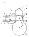
- the internal combustion engine shown only in principle in the figures is designated by 10 and consists of a carburetor 11, which is arranged on an intake flange 20 of a cylinder 30.
- a gasification part (venturi) 12 is formed, into which the air flows in through the intake part 13 and the flow through which the throttle valve part 14 arranged in the gasification part 12 downstream can be regulated.
- the carburetor has the outlet channel 15 behind the throttle valve part 14.
- the partial load is in the region of the throttle valve part 14 formed nozzle chamber 16 which is connected to a control chamber, not shown.
- the housing 18 of the carburetor 11 is connected in the region of the outlet channel 15 to the intake flange 20, in which the inlet channel known per se is formed, which feeds the fuel-air mixture formed in the carburetor 11 to the inlet slot 22 in the cylinder 30, from which it flows flows into the crank chamber 34, is supplied to the combustion chamber 31 via overflow channels, not shown, and after compression by the piston 32, which consists of the piston crown 32a and the piston skirt 32b, and subsequent ignition, flows out via the outlet slot 34.
- the cylinder 30 is on a conventional one Crankcase 33 arranged.
- an additional idle channel 23 is formed in the intake flange 20 parallel to the inlet channel 21, the inlet slot 24 of which is arranged on the inside of the cylinder below the inlet slot 22 of the inlet channel 21.
- the inlet part 25 of the additional idle channel 23 is arranged directly on the carburetor 11, specifically in the transition area from Carburetor 11 to the intake flange 20.
- the inlet part 25 is designed as an annular slot 26, the extent of which comprises approximately a semicircle of the circular cross section of the inlet channel 21.
- the fuel-air mixture which arises in the region of the part-load nozzle chamber in the throttle valve part 14 is drawn in at idle by the inlet part 25 of the additional idle duct 23, as is indicated by the arrow denoted by X in the drawing. From here it is fed to the crank chamber 34 via the additional idling channel 23.
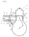
- FIGS. 2, 3 and 4 have essentially the same basic structure as the arrangement described above.
- the additional idling duct 123 connects the transition region of the carburetor 11 to the intake flange 20 directly with the crank chamber 34.
- the inlet part 125 of the additional idling duct 123 is arranged directly on the carburetor and is designed as an annular slot 126, the expansion of which is approximately comprises a semicircle of the circular cross section of the inlet duct 21.
- the outflow slot 124 is suitably arranged for the inflow of the fuel-air mixture into the crank chamber 34, and a check valve 127 is arranged in the course of the additional idling channel 123, so that the idle-fuel-air mixture can be fed in smoothly during operation of the internal combustion engine is feasible.
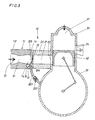
- the additional idle channel 223 is also arranged to open into the crank chamber 34 via an outflow slot 224, a check valve 225 which can be regulated through flow being arranged in the course of the additional idle channel 223.
- the inlet part 225 of the additional idling channel 223 is arranged directly in the carburetor 11 behind the outlet nozzles of the part-load nozzle chamber 16 in front of the throttle valve 19.
- the fuel is supplied via an additional idle fuel supply line 114, which connects the additional idle channel 223 directly to the part-load nozzle chamber 16.
- the inlet 325 of the additional idling duct 223 is likewise arranged directly in the carburetor behind the nozzles of the part-load nozzle chamber 16 and in front of the throttle valve 19.
- An additional idle fuel line 314 is also provided, which connects the part-load nozzle chamber 16 to the additional idle duct 323.
- the idle channel 323 is formed parallel to the inlet channel 21 in the intake flange 20, the inlet slot 324 of which is arranged on the inside of the cylinder below the inlet slot 22 of the inlet channel 21.
Abstract
Description
Die Erfindung betrifft eine Zweitakt-Brennkraftmaschine mit einem Vergaser mit einem Vergasungsteil (Venturi), einem den Vergasungsteil vorgeschalteten Ansaugteil, einem Drosselklappenteil, einem dem Drosselklappenteil nachgeschalteten Ausgangskanal, einer Haupt- und einer Teillastdüsenkammer und einer druckbeaufschlagbaren Kraftstoffzuführungsleitung, einem Zylinder mit einem Einlaßkanal mit einem Einlaßschlitz, wobei der im Ansaugflansch ausgebildete Einlaßkanal mit dem Ausgangskanal des Vergasers verbunden ist.The invention relates to a two-stroke internal combustion engine with a carburetor with a gasification part (Venturi), a suction part upstream of the gasification part, a throttle valve part, an output channel downstream of the throttle valve part, a main and a part-load nozzle chamber and a pressurizable fuel supply line, a cylinder with an inlet channel with a Inlet slot, wherein the inlet duct formed in the intake flange is connected to the outlet duct of the carburetor.
Derartige Brennkraftmaschinen sind in allen Einsatzbereichen und insbesondere für den Einsatz bei Motorkettensägen seit langem bekannt. Für den Betrieb einer Brennkraftmaschine ist es nötig, dieser für jeden durch Drehzahl und Last gegebenen Betriebspunkt jeweils Luft und Kraftstoff in einem bestimmten Luftverhältnis zuzuführen. Der Vergaser hat dabei die Aufgabe, der angesaugten Luft die richtige Menge des Kraftstoffes zuzuteilen und die für die Einstellung des Betriebspunktes nötige Bemessung der Menge des Gemisches aus Luft und Kraftstoff durchzuführen. Diese Aufbereitung und Versorgung der Brennkraftmaschine mit einem entsprechenden Kraftstoff-Luft-Gemisch ist während des Betriebes der Brennkraftmaschine zumeist problemlos durchführbar.Such internal combustion engines have long been known in all areas of application and in particular for use in motor chain saws. For the operation of an internal combustion engine, it is necessary to supply it with air and fuel in a certain air ratio for each operating point given by speed and load. The task of the carburetor is to allocate the correct amount of fuel to the intake air and to carry out the measurement of the amount of the mixture of air and fuel necessary for setting the operating point. This preparation and supply of the internal combustion engine with a corresponding fuel-air mixture can usually be carried out without problems during operation of the internal combustion engine.
Zweitaktmotoren, die aus thermischen oder schwingungstechnischen Gründen über lange Ansaugkanäle vom Vergaser mit einem Kraftstoff-Luft-Gemisch versorgt werden, leiden generell unter einer thermischen und lagebedingten Leerlaufsensibilität, die zu Drehzahlschwankungen im Leerlauf und zum Absterben des Motors führen können.Two-stroke engines, which are supplied with a fuel-air mixture from the carburetor via long intake ducts for thermal or vibration-related reasons, generally suffer from thermal and position-related idling sensitivity, which can lead to fluctuations in engine speed when idling and to engine stall.
Hervorgerufen wird dieser Effekt durch Kondensation, Pfützenbildung wegen zu großer Oberfläche und gleichzeitigem Mangel an Luftgeschwindigkeit im Ansaugkanal des Motors im LeerlaufbetriebThis effect is caused by condensation, puddling due to too large a surface and, at the same time, a lack of air speed in the intake duct of the engine when idling
Mit den bisher bekannten Vergasern konnte dieses Problem nicht gelöst werden. Eine Teillösung kann in der Verwendung eines Vergasers mit kurzem Ansaugkanal bestehen, wobei die dabei auftretenden thermischen Probleme durch einen "Injektion-Vergaser" überbrückt werden müssen. Sofern jedoch lange Ansaugkanäle konzipiert werden müssen, treten die genannten Probleme aufThis problem could not be solved with the carburetors known to date. A partial solution can consist in the use of a carburetor with a short intake duct, whereby the thermal problems that arise must be bridged by an "injection carburetor". However, if long intake ducts have to be designed, the problems mentioned arise
Es ist daher Aufgabe der vorliegenden Erfindung, eine Brennkraftmaschine mit einem Vergaser so weiterzubilden, daß eine Leerlaufstabilisierung erreicht werden kann.It is therefore an object of the present invention to develop an internal combustion engine with a carburetor so that idle stabilization can be achieved.
Zur Lösung dieser Aufgabe wird eine Zweitakt-Brennkraftmaschine mit einem Vergasungsteil (Venturi), einem dem Vergasungsteil vorgeschalteten Ansaugteil, einem Drosselklappenteil, einem dem Drosselklappenteil nachgeschalteten Ausgangskanal, einer Haupt- und einer Teillastdüsenkammer und einer druckbeaufschlagbaren Kraftstoffzuführungsleitung, einem auf einer Kurbelkammer angeordneten Zylinder mit einem Einlaßkanal mit einem Einlaßschlitz, wobei der im Ansaugflansch ausgebildete Einlaßkanal mit dem Ausgangskanal des Vergasers verbunden ist, vorgeschlagen, daß der Kurbelkammer Kraftstoff-Luft-Gemisch durch einen zusätzlichen Leerlaufkanal zuführbar ist.To solve this problem, a two-stroke internal combustion engine with a gasification part (Venturi), an intake part upstream of the gasification part, a throttle valve part, an outlet duct downstream of the throttle valve part, a main and a part-load nozzle chamber and a pressurizable fuel supply line, a cylinder arranged on a crank chamber with a Inlet duct with an inlet slot, the inlet duct formed in the intake flange being connected to the outlet duct of the carburetor, proposed that the fuel-air mixture can be supplied to the crank chamber through an additional idling duct.
Hierbei ist vorzusehen, daß im Leerlauf das Kraftstoff-Luft-Gemisch durch den zusätzlichen Leerlaufkanal angesaugt wird.It should be provided that the fuel-air mixture is drawn in through the additional idling duct when idling.
Bevorzugterweise ist dabei vorgesehen, daß der zusätzliche Leerlaufkanal durch das Kolbenhemd gesteuert wird und vor dem eigentlichen Einlaßkanal geöffnet wird, so daß überwiegend ein Vakuum im zusätzlichen Leerlaufkanal vorliegt. In diesem Fall besteht der Leerlaufkanal aus einem unterhalb des eigentlichen Einlaßschlitzes, d.h näher zum Kurbelgehäuse angeordneten zusätzlichen Einlaßschlitz mit vorgeschaltetem Kanal.It is preferably provided that the additional idling duct is controlled by the piston skirt and is opened before the actual inlet duct, so that there is predominantly a vacuum in the additional idling duct. In this case, the idle channel consists of an additional inlet slot with an upstream channel arranged below the actual inlet slot, i.e. closer to the crankcase.
Es kann jedoch auch vorgesehen sein, den zusätzlichen Leerlaufkanal anders anzuordnen und/oder anders zu steuern, beispielsweise durch ein Ventil, wie z.B. ein Membranventil oder ein Flatterventil, das einen überwiegenden Vakuumbetrieb im Leerlaufkanal gewährleistet und einen Anschluß direkt an die Kurbelkammer zuläßt.However, it can also be provided that the additional idling duct be arranged differently and / or controlled differently, for example by a valve, such as e.g. a diaphragm valve or a flutter valve, which ensures predominant vacuum operation in the idle channel and allows a connection directly to the crank chamber.
Bevorzugterweise ist, damit die Leistungscharakteristik der Brennkraftmaschine nicht beeinflußt wird, und im Leerlauf hohe Luftgeschwindigkeiten erzeugt werden, vorzusehen, daß der Leerlaufkanal sehr eng ausgeführt wird, wobei sich eine Auslegung auf 1/10 des Einlaßzeitquerschnittes empfiehlt.It is preferable, so that the performance characteristics of the internal combustion engine are not influenced, and high air velocities are generated when idling, that the idling duct is designed to be very narrow, a design to 1/10 of the intake time cross section being recommended.
Gemäß einer bevorzugten Ausführungsform ist vorgesehen, das Kraftstoff-Luft-Gemisch im Leerlaufbetrieb direkt am Vergaser anzusaugen, wobei in diesem Fall zwischen Vergaser und Ansaugflansch ein ringförmiger Schlitz ausgebildet ist.According to a preferred embodiment, it is provided that the fuel-air mixture is drawn in directly at the carburetor in idle mode, in which case an annular slot is formed between the carburetor and the intake flange.
Gemäß einer anderen Ausbildungsvariante ist vorgesehen, daß der Leerlauf-Kraftstoff direkt aus der Teillastdüsenkammer in den zusätzlichen Leerlaufkanal eingeführt wird, wobei die Luft aus dem Bereich zwischen dem Luftfilter und der Drosselklappe angesaugt wird.According to another embodiment variant, it is provided that the idle fuel is introduced directly from the part-load nozzle chamber into the additional idle channel, the air being sucked in from the area between the air filter and the throttle valve.
Die Ausbildung des Leerlaufsystems in dieser Weise führt dazu, daß sich verschiedene Vorteile ergeben, nämlich keine Lageempfindlichkeit, geringe Temperaturempfindlichkeit und aufgrund des geringen Querschnittes des zusätzlichen Leerlaufkanals eine geringe Kondensationsoberfläche und eine gleichzeitig hohe Luftgeschwindigkeit. Hierdurch wird sowohl das Startverhalten verbessert als auch der Leerlauf stabilisiert. Gleichzeitig wird das Beschleunigungsverhalten verbessert, da ein relativ "fettes Leerlaufgemisch" benutzt werden kann.The design of the idling system in this way leads to various advantages, namely no position sensitivity, low temperature sensitivity and, due to the small cross section of the additional idling duct, a small condensation surface and a high air speed at the same time. This improves starting behavior and stabilizes idling. At the same time, the acceleration behavior is improved since a relatively "rich idling mixture" can be used.
Im Hinblick darauf, daß der Leerlauf stabilisiert wird bzw. der Rundlauf der Brennkraftmaschine verbessert wird, kann die Leerlaufdrehzahl insgesamt verringert werden.In view of the fact that idling is stabilized or the concentricity of the internal combustion engine is improved, the idling speed can be reduced overall.
Bevorzugterweise ergibt sich dabei eine einfache Leerlaufjustierung, da die Brennkraftmaschine bei dieser Ausgestaltung auf die Einstellung des Drosselklappenanschlages und der Leerlaufdüse sehr präzise reagiert.This preferably results in a simple idle adjustment, since the internal combustion engine reacts very precisely to the setting of the throttle valve stop and the idle nozzle in this embodiment.
Als weiterer Vorteil hat es sich gezeigt, daß eine vereinfachte Ausführung des Ansaugkanals vorgesehen werden kann. Da nämlich Unebenheiten sich nicht mehr auf das Leerlaufverhalten auswirken können, kann der Vergaser problemlos durch einen langen, isolierenden Ansaugschlauch vor Überhitzung geschützt werden.As a further advantage, it has been shown that a simplified design of the intake duct can be provided. Because bumps can no longer affect idling behavior, the carburetor can be protected from overheating with a long, insulating intake hose.
Vorteilhafte Ausgestaltungen bzw. zweckmäßige Weiterbildungen der Erfindung sind in den Unteransprüchen gekennzeichnet. Dabei sind Kombinationen der verschiedenen Ausführungsformen ebenso möglich wie die Anwendung auf Mehrzylinder-Zweitakt-Brennkraftmaschinen.Advantageous refinements or expedient developments of the invention are characterized in the subclaims. Combinations of the different embodiments are possible, as is the application to multi-cylinder two-stroke internal combustion engines.
Ausführungsbeispiele der Erfindung werden nachstehend anhand der Zeichnung näher erläutert. Es zeigen
- Fig. 1 in einer schematischen Prinzipdarstellung einen an einem Ansaugflansch einer Einzylinderbrennkraftmaschine angeordneten Vergaser in einem senkrechten Schnitt,
- Fig. 2 in einer schematischen Prinzipdarstellung eine weitere Ausführungsform einer Anordnung eines Vergasers an einer Brennkraftmaschine in einem senkrechten Schnitt,
- Fig. 3 in einer schematischen Prinzipdarstellung eine weitere Ausführungsform einer Anordnung eines Vergasers an einer Brennkraftmaschine in einem senkrechten Schnitt und
- Fig. 4 in einer schematischen Prinzipdarstellung eine weitere Ausführungsform einer Anordnung eines Vergasers an einer Brennkraftmaschine in einem senkrechten Schnitt.
- 1 shows a schematic basic illustration of a carburetor arranged on an intake flange of a single-cylinder internal combustion engine in a vertical section,
- 2 shows a schematic basic illustration of a further embodiment of an arrangement of a carburetor on an internal combustion engine in a vertical section,
- 3 shows a schematic basic illustration of a further embodiment of an arrangement of a carburetor on an internal combustion engine in a vertical section and
- Fig. 4 is a schematic representation of a further embodiment of an arrangement of a carburetor on an internal combustion engine in a vertical section.
Die in den Figuren nur prinzipiell dargestellte Brennkraftmaschine ist mit 10 bezeichnet und besteht aus einem Vergaser 11, der an einem Ansaugflansch 20 eines Zylinders 30 angeordnet ist. Im Gehäuse 18 des Vergasers 11 ist ein Vergasungsteil (Venturi) 12 ausgebildet, in das die Luft durch den Ansaugteil 13 einströmt und dessen Durchfluß durch die in dem Vergasungsteil 12 nachgeschalteten Drosselklappenteil 14 angeordnete Drosselklappe 19 regelbar ist. Hinter dem Drosselklappenteil 14 weist der Vergaser den Ausgangskanal 15 auf. Im Bereich des Drosselklappenteils 14 ist die Teillast düsenkammer 16 ausgebildet, die mit einer nicht dargestellten Regelkammer verbunden ist.The internal combustion engine shown only in principle in the figures is designated by 10 and consists of a
Das Gehäuse 18 des Vergasers 11 ist im Bereich des Ausgangskanals 15 mit dem Ansaugflansch 20 verbunden, in dem der an sich bekannte Einlaßkanal ausgebildet ist, der das im Vergaser 11 gebildete Kraftstoff-Luft-Gemisch dem Einlaßschlitz 22 im Zylinder 30 zuführt, aus dem es in die Kurbelkammer 34 strömt, über nicht dargestellte Überströmkanäle dem Brennraum 31 zugeführt wird und nach Kompression durch den Kolben 32, der aus dem Kolbenboden 32a und dem Kolbenhemd 32b besteht, und nachfolgender Entzündung über den Auslaßschlitz 34 ausströmt Der Zylinder 30 ist dabei auf einem üblichen Kurbelkasten 33 angeordnet.The
In Fig. 1 ist im Ansaugflansch 20 parallel zum Einlaßkanal 21 ein zusätzlicher Leerlaufkanal 23 ausgebildet, dessen Einlaßschlitz 24 zylinderinnenseitig unterhalb des Einlaßschlitzes 22 des Einlaßkanals 21 angeordnet ist Der Einlaßteil 25 des zusätzlichen Leerlaufkanals 23 ist direkt am Vergaser 11 angeordnet, und zwar im Übergangsbereich vom Vergaser 11 zum Ansaugflansch 20. Der Einlaßteil 25 ist dabei als ringförmiger Schlitz 26 ausgebildet, dessen Ausdehnung etwa einen Halbkreis des kreisförmigen Querschnitts des Einlaßkanals 21 umfaßt.In Fig. 1, an
Das im Bereich der Teillastdüsenkammer im Drosselklappenteil 14 entstehende Kraftstoff-Luft-Gemisch wird im Leerlauf vom Einlaßteil 25 des zusätzlichen Leerlaufkanals 23 angesaugt, wie dies durch den mit X bezeichneten Pfeil in der Zeichnung angedeutet ist. Von hier aus wird es über den zusätzlichen Leerlaufkanal 23 der Kurbelkammer 34 zugeführt.The fuel-air mixture which arises in the region of the part-load nozzle chamber in the
Die in den Fig. 2, 3 und 4 dargestellten Ausführungsformen weisen im wesentlichen den gleichen Grundaufbau auf wie die voranstehend beschriebene Anordnung.The embodiments shown in FIGS. 2, 3 and 4 have essentially the same basic structure as the arrangement described above.
Bei der in Fig. 2 dargestellten Ausführungsform verbindet der zusätzliche Leerlaufkanal 123 den Übergangsbereich des Vergasers 11 zum Ansaugflansch 20 direkt mit der Kurbelkammer 34. Dabei ist der Einlaßteil 125 des zusätzlichen Leerlaufkanals 123 direkt am Vergaser angeordnet und als ringförmiger Schlitz 126 ausgebildet, dessen Ausdehnung etwa einen Halbkreis des kreisförmigen Querschnittes des Einlaßkanals 21 umfaßt. Der Ausströmschlitz 124 ist für die Einströmung des Kraftstoff-Luft-Gemisches in die Kurbelkammer 34 geeignet angeordnet und im Verlauf des zusätzlichen Leerlaufkanals 123 ist ein Rückschlagventil 127 angeordnet, so daß eine problemlose Zuführung des Leerlauf-Kraftstoff-Luft-Gemisches während des Betriebes der Brennkraftmaschine durchführbar ist.In the embodiment shown in FIG. 2, the additional
Bei der in Fig. 3 dargestellten Ausführungsform ist der zusätzliche Leerlaufkanal 223 ebenfalls über einen Ausströmschlitz 224 in die Kurbelkammer 34 mündend angeordnet, wobei im Verlauf des zusätzlichen Leerlaufkanals 223 ein durchflußregelbares Rückschlagventil 225 angeordnet ist. Der Einlaßteil 225 des zusätzlichen Leerlaufkanals 223 ist direkt im Vergaser 11 hinter den Austrittdüsen der Teillastdüsenkammer 16 vor der Drosselklappe 19 angeordnet. Die Kraftstoffversorgung erfolgt dabei über eine zusätzliche Leerlauf-Kraftstoff-Zuführungsleitung 114, die den zusätzlichen Leerlaufkanal 223 direkt mit der Teillastdüsenkammer 16 verbindet.In the embodiment shown in FIG. 3, the
Bei der in Fig. 4 dargestellten Ausführungsform ist der Einlaß 325 des zusätzlichen Leerlaufkanals 223 ebenfalls direkt im Vergaser hinter den Düsen der Teillastdüsenkammer 16 und vor der Drosselklappe 19 angeordnet. Ebenfalls ist eine zusätzliche Leerlauf-Kraftstoffleitung 314 vorgesehen, die die Teillastdüsenkammer 16 mit dem zusätzlichen Leerlaufkanal 323 verbindet. Der Leerlaufkanal 323 ist dabei parallel zum Einlaßkanal 21 im Ansaugflansch 20 ausgebildet, wobei dessen Einlaßschlitz 324 zyinderinnenseitig unterhalb des Einlaßschlitzes 22 des Einlaßkanals 21 angeordnet ist.In the embodiment shown in FIG. 4, the
Die Erfindung ist nicht beschränkt auf die in den Zeichnungen dargestellten und voranstehend beschriebenen Ausführungsfiguren. Eine andere Kombination der verschiedenen Gestaltungsmöglichkeiten des Einlaßteiles für den zusätzlichen Leerlaufkanal liegt ebenso im Rahmen der Erfindung wie die Anordnung aufwendigerer Steuerelemente im Verlauf des zusätzlichen Einlaßkanals.The invention is not restricted to the embodiment figures shown in the drawings and described above. Another combination of the different design options of the inlet part for the additional idling duct is within the scope of the invention, as is the arrangement of more complex control elements in the course of the additional inlet duct.
Claims (11)
dadurch gekennzeichnet,
daß der Kurbelkammer (34) Kraftstoff-Luft-Gemisch durch einen zusätzlichen Leerlaufkanal (23; 123; 223; 323) zuführbar ist.1. Two-stroke internal combustion engine with a carburetor with a gasification part (Venturi), a suction part upstream of the gasification part, a throttle valve part, an output channel downstream of the throttle valve part, a main and a part-load nozzle chamber and a pressurizable fuel supply line, a cylinder arranged on a crank chamber with an inlet channel with an inlet slot, the inlet duct formed in the intake flange being connected to the outlet duct of the carburetor,
characterized,
that the crank chamber (34) fuel-air mixture can be supplied through an additional idle channel (23; 123; 223; 323).
dadurch gekennzeichnet,
daß ein den zusätzlichen Leerlaufkanal (23; 323) zylinderinnenseitig begrenzende Einlaßschlitz (24; 324) im Zylinder (30) unterhalb des Einlaßschlitzes (22) des Einlaßkanals (21) angeordnet ist.2. Two-stroke internal combustion engine according to claim 1,
characterized,
that an inlet slot (24; 324) delimiting the additional idling channel (23; 323) on the cylinder side is arranged in the cylinder (30) below the inlet slot (22) of the inlet channel (21).
dadurch gekennzeichnet,
daß der zusätzliche Leerlaufkanal (23; 123; 223; 323) durch ein Steuerventil (127; 227; 327) querschnittsveränderlich ist3. two-stroke internal combustion engine according to claim 1 or 2,
characterized,
that the additional idle channel (23; 123; 223; 323) can be changed in cross section by a control valve (127; 227; 327)
dadurch gekennzeichnet,
daß ein Ausströmschlitz (124; 224) des zusätzlichen Leerlaufkanals (123; 223) in die Kurbelkammer (34) mündend angeordnet ist und das Steuerventil ein Rückschlagventil (127; 227) ist4. Two-stroke internal combustion engine according to claim 3,
characterized,
that an outflow slot (124; 224) of the additional Idle channel (123; 223) is arranged opening into the crank chamber (34) and the control valve is a check valve (127; 227)
dadurch gekennzeichnet,
daß der Querschnitt des zusätzlichen Leerlaufkanals (23) in bezug auf den Zeitquerschnitt des Leerlaufkanals (21) klein, insbesondere ca 1:10 ist.5. Two-stroke internal combustion engine according to one of claims 1 to 4,
characterized,
that the cross section of the additional idle channel (23) is small, in particular about 1:10, with respect to the time cross section of the idle channel (21).
dadurch gekennzeichnet,
daß ein Einlaßteil (225; 325) des zusätzlichen Leerlaufkanals (223; 323) direkt im Vergaser (11) vor der Drosselklappe (19) angeordnet ist.6. Two-stroke internal combustion engine according to one of claims 1 to 5,
characterized,
that an inlet part (225; 325) of the additional idling channel (223; 323) is arranged directly in the carburetor (11) in front of the throttle valve (19).
dadurch gekennzeichnet,
daß der Einlaßteil (25; 125) des zusätzlichen Leerlaufkanals (23; 123) im Bereich hinter der Drosselklappe (19) angeordnet ist.7. Two-stroke internal combustion engine according to claim 6,
characterized,
that the inlet part (25; 125) of the additional idling channel (23; 123) is arranged in the area behind the throttle valve (19).
dadurch gekennzeichnet,
daß der Einlaßteil (25; 125) des zusätzlichen Leerlaufkanals (23; 123) im Übergangsbereich vom Vergaser (11) zum Ansaugflansch (20) ausgebildet ist.8. Two-stroke internal combustion engine according to claim 6,
characterized,
that the inlet part (25; 125) of the additional idling duct (23; 123) is formed in the transition area from the carburetor (11) to the intake flange (20).
dadurch gekennzeichnet,
daß der Einlaßteil (25; 125) des zusätzlichen Leer laufkanals (23) als ringförmiger Schlitz (26; 126) ausgebildet ist9. Two-stroke internal combustion engine according to one of claims 1 to 8,
characterized,
that the inlet part (25; 125) of the additional empty running channel (23) is designed as an annular slot (26; 126)
dadurch gekennzeichnet,
daß der Einlaßteil (25; 125) im Ansaugteil (13) oder im Vergasungsteil (12) des Vergasers (11) angeordnet ist und dem zusätzlichen Leerlaufkanal (23; 123) über einen zusätzlichen Kraftstoffkanal Kraftstoff zuführbar ist.10. Two-stroke internal combustion engine according to one of claims 1 to 9,
characterized,
that the inlet part (25; 125) is arranged in the intake part (13) or in the gasification part (12) of the carburetor (11) and the additional idling duct (23; 123) can be supplied with fuel via an additional fuel duct.
dadurch gekennzeichnet,
daß der zusätzliche Kraftstoffkanal (114) an die Teillastdüsenkammer (16) angeschlossen ist.11. Two-stroke internal combustion engine according to one of claims 1 to 10,
characterized,
that the additional fuel channel (114) is connected to the part-load nozzle chamber (16).
Applications Claiming Priority (2)
| Application Number | Priority Date | Filing Date | Title |
|---|---|---|---|
| DE3819971 | 1988-06-11 | ||
| DE19883819971 DE3819971A1 (en) | 1988-06-11 | 1988-06-11 | TWO-STROKE INTERNAL COMBUSTION ENGINE WITH A CARBURETTOR |
Publications (2)
| Publication Number | Publication Date |
|---|---|
| EP0346797A2 true EP0346797A2 (en) | 1989-12-20 |
| EP0346797A3 EP0346797A3 (en) | 1990-05-09 |
Family
ID=6356378
Family Applications (1)
| Application Number | Title | Priority Date | Filing Date |
|---|---|---|---|
| EP89110592A Withdrawn EP0346797A3 (en) | 1988-06-11 | 1989-06-12 | Two-stroke combustion engine with a carburettor |
Country Status (2)
| Country | Link |
|---|---|
| EP (1) | EP0346797A3 (en) |
| DE (1) | DE3819971A1 (en) |
Citations (11)
| Publication number | Priority date | Publication date | Assignee | Title |
|---|---|---|---|---|
| GB559771A (en) * | 1943-01-18 | 1944-03-03 | Morris Motors Ltd | Improvements relating to two-stroke internal combustion engines |
| US2388331A (en) * | 1943-04-14 | 1945-11-06 | Metal Products Corp | Fuel supply for two-cycle, crankcase compression engines |
| US2759716A (en) * | 1954-01-21 | 1956-08-21 | Acf Ind Inc | Idling system for two-cycle engines |
| DE1046395B (en) * | 1956-03-10 | 1958-12-11 | Auto Union Gmbh | Idle operation of two-stroke internal combustion engines |
| CH367002A (en) * | 1956-05-23 | 1963-01-31 | Auto Union Gmbh | Two-stroke internal combustion engine |
| DE1804339A1 (en) * | 1968-10-22 | 1970-05-21 | Audi Nsu Auto Union Ag | Carburetor system for internal combustion engines |
| US4159012A (en) * | 1977-06-13 | 1979-06-26 | Textron Inc. | Diaphragm type carburetor for a two-stroke cycle engine |
| GB2088477A (en) * | 1980-12-29 | 1982-06-09 | Brunswick Corp | Idle fuel system for a two-cycle engine |
| GB2125480A (en) * | 1982-08-09 | 1984-03-07 | Outboard Marine Corp | Fuel system for a crankcase compression two-stroke |
| JPS59180026A (en) * | 1983-03-31 | 1984-10-12 | Suzuki Motor Co Ltd | Intake apparatus for two-cycle internal-combustion engine |
| JPS6043122A (en) * | 1983-08-18 | 1985-03-07 | Kubota Ltd | Fuel supplying apparatus for two-cycle engine |
-
1988
- 1988-06-11 DE DE19883819971 patent/DE3819971A1/en not_active Withdrawn
-
1989
- 1989-06-12 EP EP89110592A patent/EP0346797A3/en not_active Withdrawn
Patent Citations (11)
| Publication number | Priority date | Publication date | Assignee | Title |
|---|---|---|---|---|
| GB559771A (en) * | 1943-01-18 | 1944-03-03 | Morris Motors Ltd | Improvements relating to two-stroke internal combustion engines |
| US2388331A (en) * | 1943-04-14 | 1945-11-06 | Metal Products Corp | Fuel supply for two-cycle, crankcase compression engines |
| US2759716A (en) * | 1954-01-21 | 1956-08-21 | Acf Ind Inc | Idling system for two-cycle engines |
| DE1046395B (en) * | 1956-03-10 | 1958-12-11 | Auto Union Gmbh | Idle operation of two-stroke internal combustion engines |
| CH367002A (en) * | 1956-05-23 | 1963-01-31 | Auto Union Gmbh | Two-stroke internal combustion engine |
| DE1804339A1 (en) * | 1968-10-22 | 1970-05-21 | Audi Nsu Auto Union Ag | Carburetor system for internal combustion engines |
| US4159012A (en) * | 1977-06-13 | 1979-06-26 | Textron Inc. | Diaphragm type carburetor for a two-stroke cycle engine |
| GB2088477A (en) * | 1980-12-29 | 1982-06-09 | Brunswick Corp | Idle fuel system for a two-cycle engine |
| GB2125480A (en) * | 1982-08-09 | 1984-03-07 | Outboard Marine Corp | Fuel system for a crankcase compression two-stroke |
| JPS59180026A (en) * | 1983-03-31 | 1984-10-12 | Suzuki Motor Co Ltd | Intake apparatus for two-cycle internal-combustion engine |
| JPS6043122A (en) * | 1983-08-18 | 1985-03-07 | Kubota Ltd | Fuel supplying apparatus for two-cycle engine |
Non-Patent Citations (2)
| Title |
|---|
| PATENT ABSTRACTS OF JAPAN vol. 9, no. 172 (M-397)(1895) 17 Juli 1985; & JP-A-60 043 122 (KUBOTA TEKKO) 07 März 1985 * |
| PATENT ABSTRACTS OF JAPAN vol. 9, no. 38 (M-358)(1761) 19 Februar 1985; & JP-A-59 180 026 (SUZUKI) 12 Oktober 1984 * |
Also Published As
| Publication number | Publication date |
|---|---|
| EP0346797A3 (en) | 1990-05-09 |
| DE3819971A1 (en) | 1989-12-14 |
Similar Documents
| Publication | Publication Date | Title |
|---|---|---|
| DE60009266T2 (en) | CYLINDER FOR AN INTERNAL COMBUSTION ENGINE | |
| DE3624899C2 (en) | ||
| DE2120949A1 (en) | Device for connecting vibrations of a multi-cylinder internal combustion engine ignited by spark plugs | |
| DE2609082C2 (en) | Carburettors for internal combustion engines | |
| DE3823525A1 (en) | CARBURETTOR FOR COMBUSTION ENGINES | |
| AT4966U1 (en) | FOUR-STOCK COMBUSTION ENGINE WITH AT LEAST TWO INLET VALVES | |
| DE19939898A1 (en) | Fuel-air supply device for an internal combustion engine | |
| DE2211698A1 (en) | Carburetor with delay circuit | |
| DE3024181A1 (en) | ROTOR CARBURETOR DEVICE WITH IDLE MIXING FOR INTERNAL COMBUSTION ENGINES | |
| DE4416693A1 (en) | Carburetor | |
| DE2907223A1 (en) | FUEL INTAKE SYSTEM FOR COMBUSTION ENGINES WITH MULTIPLE CYLINDERS | |
| DE2060612A1 (en) | Carburetor | |
| DE2448819A1 (en) | COMBUSTION MACHINE | |
| DE2452342C3 (en) | Carburettors for internal combustion engines | |
| EP0346797A2 (en) | Two-stroke combustion engine with a carburettor | |
| DE2411698A1 (en) | Trochoidal four stroke rotary piston engine - has multi-sided piston on cam shaft with inlet channels supplied by separate carburretors | |
| DE949913C (en) | Carburettors for internal combustion engines | |
| DE602004005062T2 (en) | CARB | |
| DE3243702A1 (en) | CARBURETTOR CONNECTION PIPE FOR INTERNAL COMBUSTION ENGINES | |
| DE3314206C2 (en) | Changeable venturi carburetor | |
| DE2601605C3 (en) | Downdraft carburetor with acceleration pump for internal combustion engines | |
| WO1985003741A1 (en) | Additional air supply device for carburators of internal combustion engines | |
| DE2440354A1 (en) | TWO-STROKE GASOLINE ENGINE | |
| DE1576442A1 (en) | Additional device for carburettor engines | |
| DE3215605C1 (en) | Carburettor for internal combustion engines |
Legal Events
| Date | Code | Title | Description |
|---|---|---|---|
| PUAI | Public reference made under article 153(3) epc to a published international application that has entered the european phase |
Free format text: ORIGINAL CODE: 0009012 |
|
| AK | Designated contracting states |
Kind code of ref document: A2 Designated state(s): AT BE CH DE ES FR GB GR IT LI LU NL SE |
|
| RBV | Designated contracting states (corrected) |
Designated state(s): DE FR GB IT SE |
|
| PUAL | Search report despatched |
Free format text: ORIGINAL CODE: 0009013 |
|
| AK | Designated contracting states |
Kind code of ref document: A3 Designated state(s): DE FR GB IT SE |
|
| STAA | Information on the status of an ep patent application or granted ep patent |
Free format text: STATUS: THE APPLICATION IS DEEMED TO BE WITHDRAWN |
|
| 18D | Application deemed to be withdrawn |
Effective date: 19901112 |