EP0344824A1 - Verfahren zum Einbau von Kunststoffrohrstücken in zu sanierende Abwasserrohre - Google Patents
Verfahren zum Einbau von Kunststoffrohrstücken in zu sanierende Abwasserrohre Download PDFInfo
- Publication number
- EP0344824A1 EP0344824A1 EP89114356A EP89114356A EP0344824A1 EP 0344824 A1 EP0344824 A1 EP 0344824A1 EP 89114356 A EP89114356 A EP 89114356A EP 89114356 A EP89114356 A EP 89114356A EP 0344824 A1 EP0344824 A1 EP 0344824A1
- Authority
- EP
- European Patent Office
- Prior art keywords
- plastic pipe
- pipe
- plastic
- sewage
- sleeve
- Prior art date
- Legal status (The legal status is an assumption and is not a legal conclusion. Google has not performed a legal analysis and makes no representation as to the accuracy of the status listed.)
- Granted
Links
Images


Classifications
-
- E—FIXED CONSTRUCTIONS
- E03—WATER SUPPLY; SEWERAGE
- E03F—SEWERS; CESSPOOLS
- E03F3/00—Sewer pipe-line systems
- E03F3/06—Methods of, or installations for, laying sewer pipes
-
- F—MECHANICAL ENGINEERING; LIGHTING; HEATING; WEAPONS; BLASTING
- F16—ENGINEERING ELEMENTS AND UNITS; GENERAL MEASURES FOR PRODUCING AND MAINTAINING EFFECTIVE FUNCTIONING OF MACHINES OR INSTALLATIONS; THERMAL INSULATION IN GENERAL
- F16L—PIPES; JOINTS OR FITTINGS FOR PIPES; SUPPORTS FOR PIPES, CABLES OR PROTECTIVE TUBING; MEANS FOR THERMAL INSULATION IN GENERAL
- F16L55/00—Devices or appurtenances for use in, or in connection with, pipes or pipe systems
- F16L55/16—Devices for covering leaks in pipes or hoses, e.g. hose-menders
- F16L55/179—Devices for covering leaks in pipes or hoses, e.g. hose-menders specially adapted for bends, branch units, branching pipes or the like
-
- F—MECHANICAL ENGINEERING; LIGHTING; HEATING; WEAPONS; BLASTING
- F16—ENGINEERING ELEMENTS AND UNITS; GENERAL MEASURES FOR PRODUCING AND MAINTAINING EFFECTIVE FUNCTIONING OF MACHINES OR INSTALLATIONS; THERMAL INSULATION IN GENERAL
- F16L—PIPES; JOINTS OR FITTINGS FOR PIPES; SUPPORTS FOR PIPES, CABLES OR PROTECTIVE TUBING; MEANS FOR THERMAL INSULATION IN GENERAL
- F16L55/00—Devices or appurtenances for use in, or in connection with, pipes or pipe systems
- F16L55/26—Pigs or moles, i.e. devices movable in a pipe or conduit with or without self-contained propulsion means
- F16L55/265—Pigs or moles, i.e. devices movable in a pipe or conduit with or without self-contained propulsion means specially adapted for work at or near a junction between a main and a lateral pipe
-
- E—FIXED CONSTRUCTIONS
- E03—WATER SUPPLY; SEWERAGE
- E03F—SEWERS; CESSPOOLS
- E03F3/00—Sewer pipe-line systems
- E03F3/06—Methods of, or installations for, laying sewer pipes
- E03F2003/065—Refurbishing of sewer pipes, e.g. by coating, lining
-
- Y—GENERAL TAGGING OF NEW TECHNOLOGICAL DEVELOPMENTS; GENERAL TAGGING OF CROSS-SECTIONAL TECHNOLOGIES SPANNING OVER SEVERAL SECTIONS OF THE IPC; TECHNICAL SUBJECTS COVERED BY FORMER USPC CROSS-REFERENCE ART COLLECTIONS [XRACs] AND DIGESTS
- Y10—TECHNICAL SUBJECTS COVERED BY FORMER USPC
- Y10T—TECHNICAL SUBJECTS COVERED BY FORMER US CLASSIFICATION
- Y10T29/00—Metal working
- Y10T29/49—Method of mechanical manufacture
- Y10T29/49826—Assembling or joining
- Y10T29/49828—Progressively advancing of work assembly station or assembled portion of work
- Y10T29/49831—Advancing station
Definitions
- the invention relates to a method for installing plastic pipe pieces in sewage pipes to be renovated with a lateral outlet, wherein a lateral outlet opening is attached to the plastic pipe pieces, which is located at the location of the outlet when the plastic pipe piece is installed.
- pipe pieces e.g. B. short pipes
- sewer pipes to be rehabilitated The introduction of pipe pieces, e.g. B. short pipes, in sewer pipes to be rehabilitated, is unproblematic wherever there is a continuous route without side outlets.
- the renovation can be carried out from the manholes without external earthwork.
- the cuff is filled.
- the sleeve remains in its installed position. It is therefore not removed again after the annular space filling, which is usually done with concrete or concrete-like materials, has hardened.
- a sewage pipe F to be renovated has an outlet or branch G.
- A is the already installed plastic pipe section that ends adjacent to the outlet G.
- a transport device C which runs on wheels in the exemplary embodiment shown, carries a receptacle 1 with a plurality of arms 1a which extend radially outwards and firmly grasp the plastic pipe piece B to be installed from the inside.
- the axis of the receptacle 1 extends parallel to the tube axis.
- the transport device C is moved either via a push rod 15 or via a traction cable 18 together with the pushed-on plastic pipe section B in the axial direction.
- the receptacle 1 for the plastic pipe section B to be installed can be rotated via a first drive motor 7 and can be moved transversely to the pipe axis via a further drive motor 12. Details of these drives are explained below in connection with FIGS. 4 to 6.
- the outlet opening E of the plastic pipe piece to be installed is surrounded by an initially flat collar D.
- This sleeve can (see FIG. 2) be covered by a protective hood 20 which ensures that the flat sleeve is not mechanically damaged during transport by the sewage pipe to be renovated.
- a protective hood is not provided.
- the plastic pipe section B is pushed onto the end of the already installed plastic pipe section A.
- the cuff D is then filled with plastic or another filling material via a filling line 19.
- the arrangement of the expanded sleeve D fills the area of the annular space surrounding the outlet opening E between the plastic pipe section B and the sewage pipe F to be renovated. This ensures that no waste water can get to the outside of the plastic pipe.
- the receptacle 1 has a plate 2 arranged on the end face, onto which, with the aid of fastening screws 4, interchangeable stops 3 designed as stop plates can be screwed.
- the different diameters of the stop plates 3 are required for different plastic pipe diameters.
- the plate 2 is rotatably mounted on the transport device C about a central axis.
- a gear wheel 5 is mounted coaxially with the plate 2 and is in engagement with a drive wheel 6.
- the drive wheel 6 is driven by an electric drive motor 7 which can turn to both sides. With this drive motor 7, the turning of the plastic pipe piece to be installed can be carried out remotely.
- the drive motor 7 and the receptacle with rotary drive are fastened to a guide crossmember 17 which can be moved on guides 8 arranged parallel to one another.
- a spindle 9 extends parallel to the guides 8 and engages with a spindle nut on the guide crossmember 17.
- a gear 10 is fixedly connected to the spindle. The gear 10 is in engagement with the drive wheel 11 of a second drive motor 12.
- the drive motor 12 can rotate in both directions. As a result, the spindle is rotated accordingly and the guide crossbar is raised or lowered. The plastic pipe section held in the receptacle 1 is moved upwards or downwards accordingly.
- a push rod 15 is shown, which, like the pull rope 18 shown alternatively in FIGS. 2 and 3, can be used to move the transport device C.
- the push rod 15 also contains the various supply lines, including the supply line, which can convey plastic into the interior of the sleeve D via a filling line 19.
- Ballast 16 denotes that the transport device does not tip forward under the weight of the plastic tube piece and the receptacle.
- the transport device must first be retracted to the right, ie after the spreading arms 1a have been pulled in, before the sleeve D can be expanded.
- a different type of filling line than that shown in FIGS. 2 and 3 is required, for example a flexible filling line.
Landscapes
- Engineering & Computer Science (AREA)
- General Engineering & Computer Science (AREA)
- Mechanical Engineering (AREA)
- Public Health (AREA)
- Health & Medical Sciences (AREA)
- Water Supply & Treatment (AREA)
- Chemical & Material Sciences (AREA)
- Combustion & Propulsion (AREA)
- Hydrology & Water Resources (AREA)
- Life Sciences & Earth Sciences (AREA)
- Sewage (AREA)
- Processing And Handling Of Plastics And Other Materials For Molding In General (AREA)
- Lining Or Joining Of Plastics Or The Like (AREA)
- Separation, Recovery Or Treatment Of Waste Materials Containing Plastics (AREA)
- Diaphragms For Electromechanical Transducers (AREA)
- Medicines Containing Plant Substances (AREA)
- Emergency Protection Circuit Devices (AREA)
- Sink And Installation For Waste Water (AREA)
Abstract
Description
- Die Erfindung betrifft ein Verfahren zum Einbau von Kunststoffrohrstücken in zu sanierende Abwasserrohre mit seitlichem Abgang, wobei an den Kunststoffrohrstücken eine seitliche Abgangsöffnung angebracht wird, die bei eingebautem Kunststoffrohrstück an der Stelle des Abgangs liegt.
- Das Einbringen von Rohrstücken, z. B. Kurzrohren, in zu sanierende Abwasserrohrleitungen, ist überall dort unproblematisch, wo eine durchgehende Strecke ohne seitliche Abgänge vorliegt. In diesem Fall kann die Sanierung ohne äußere Erdarbeiten von den Kanalschächten aus vorgenommen werden.
- Problematisch ist hingegen die Sanierung an Stellen der Abwasserrohre, die seitliche Abgänge aufweisen, beispielsweise für Hausanschlüsse. Damit solche Hausanschlüsse mit dem innenliegenden Kunststoffrohr verbunden werden können, ist es erforderlich, einen seitlichen Durchbruch im innenliegenden Rohr vorzusehen und diesen Durchbruch in die richtige Position einzubauen. Dabei ist es wesentlich, daß während des Einbauvorgangs und danach sowohl eine Sperrung des Abzweigs möglichst kurzzeitig gehalten oder vollständig vermieden werden soll. Es muß dabei dafür gesorgt werden, daß nicht an der Abzweigstelle Abwasser in den Ringraum zwischen dem innenliegenden Kunststoffrohr und die Innenwand des zu sanierenden Außenrohrs gelangen kann. Außerdem muß sichergestellt werden, daß bei einem Verfüllen des Ringraums das Füllmaterial nicht vor dem Aushärten in den Abzweig oder das neue Rohr gelangt.
- Die Lösung dieser Aufgabe erfolgt dadurch, daß die seitliche Abgangsöffnung des Kunststoffrohrstücks auf der Außenseite des Kunststoffrohrstücks von einer expandierbaren Manschette umgriffen ist, die nach dem ausgerichteten Einbau expandiert wird und, eine umlaufende Absperrung bildend, den Ringspalt zwischen der Außenseite des Kunststoffrohrstücks und der Innenseite des Abwasserrohrs im Bereich neben der Abgangsöffnung ausfüllt.
- Bei einer bevorzugten Ausführungsform wird die Manschette verfüllt.
- Es hat sich ferner als zweckmäßig erwiesen, daß die Manschette mit Kunststoff verfüllt wird.
- Bei dem erfindungsgemäßen Verfahren verbleibt die Manschette in ihrer Einbaulage. Sie wird also nicht nach dem Aushärten der Ringraumverfüllung, die üblicherweise mit Beton oder betonähnlichen Materialien erfolgte, wieder entfernt.
- Durch die Verfüllung der Manschette mit Kunststoff ergibt sich eine Erhöhung der Sicherheit. Eine sichere Abdichtung des Ringraums ist bei einer derartigen Manschette auch dann gewährleistet, wenn aus verschiedenen Gründen entweder der Ringraum nicht ordnungsgemäß vollständig verfüllt worden ist oder nicht ordnungsgemäß verfüllt werden konnte oder wenn sogar absichtlich auf eine Verfüllung des Ringraums verzichtet werden soll.
- Nachstehend wird ein Ausführungsbeispiel der Erfindung anhand der Zeichnung im einzelnen erläutert.
- Es zeigen:
- Figur 1 - eine schematische Darstellung einer Baustelle zum Sanieren von Abwasserleitungen mit kurzen Kunststoffrohrstücken,
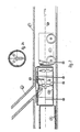
- Figur 2 - einen Längsschnitt durch eine Abzweigstelle mit eine Transportvorrichtung und Kunststoffrohrstücken,
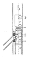
- Figur 3 - die Darstellung gemäß Figur 2 bei aufgeschobenem Kunststoffrohrstück und expandierter Manschette,
- Figur 4 - eine schematische Seitenansicht der Transportvorrichtung,
- Figur 5 - eine schematische Draufsicht auf die Transportvorrichtung,
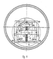
- Figur 6 - eine schematische Stirnansicht der Transportvorrichtung ohne Rohrstücke im zu sanierenden Abwasserrohr.
- Ein zu sanierendes Abwasserrohr F weist einen Abgang oder Abzweig G auf. Mit A ist das bereits fertig eingebaute Kunststoffrohrstück bezeichnet, das benachbart zum Abgang G endet. Eine Transportvorrichtung C, die im dargestellten Ausführungsbeispiel auf Rädern läuft, trägt eine Aufnahme 1 mit mehreren radial sich nach außen erstreckenden Armen 1a, die das einzubauende Kunststoffrohrstück B fest von innen erfassen. Die Achse der Aufnahme 1 erstreckt sich parallel zur Rohrachse. Die Transportvorrichtung C wird entweder über eine Schubstange 15 oder über ein Zugseil 18 gemeinsam mit dem aufgeschobenen Kunststoffrohrstück B in Achsrichtung bewegt.
- Die Aufnahme 1 für das einzubauende Kunststoffrohrstück B kann über einen ersten Antriebsmotor 7 verdreht und über einen weiteren Antriebsmotor 12 quer zur Rohrachse verfahren werden. Einzelheiten dieser Antriebe werden im Zusammenhang mit Figuren 4 bis 6 nachstehend erläutert.
- Die Abgangsöffnung E des einzubauenden Kunststoffrohrstücks ist von einer zunächst flach liegenden Manschette D umgeben. Diese Manschette kann (vgl. Figur 2) von einer Schutzhaube 20 überdeckt werden, die sicherstellt, daß die flach liegende Manschette beim Transport durch das zu sanierende Abwasserrohr nicht mechanisch beschädigt wird.
- Bei der Ausführungsform gemäß Figur 3 ist eine Schutzhaube nicht vorgesehen.
- Nach dem genauen Ausrichten der Abgangsöffnung E zum Abzweig G wird das Kunststoffrohrstück B auf das Ende des bereits eingebauten Kunststoffrohrstücks A geschoben. Danach wird die Manschette D über eine Fülleitung 19 mit Kunststoff oder einem anderen Füllmaterial befüllt. Durch die Anordnung der expandierten Manschette D ist der die Abgangsöffnung E umgebende Bereich des Ringraums zwischen dem Kunststoffrohrstück B und dem zu sanierenden Abwasserrohr F ausgefüllt. Es ist damit sichergestellt, daß kein Abwasser auf die Außenseite des Kunststoffrohrs gelangen kann.
- In den Zeichnungsfiguren 4 bis 6 ist die insgesamt mit C bezeichnete Transportvorrichtung genauer dargestellt. Von der Aufnahme 1 ist in diesen Zeichnungsfiguren lediglich das zentrale Mittelstück sichtbar.
- Die Aufnahme 1 besitzt eine stirnseitig angeordnete Platte 2, an der mit Hilfe von Befestigungsschrauben 4 auswechselbare, als Anschlagplatten ausgebildete Anschläge 3 anschraubbar sind. Die unterschiedlichen Durchmesser der Anschlagplatten 3 sind erforderlich für unterschiedliche Kunststoffrohrdurchmesser.
- Die Platte 2 ist um eine zentrale Achse drehbar an der Transportvorrichtung C gelagert. Gleichachsig mit der Platte 2 ist ein Zahnrad 5 gelagert, das mit einem Antriebsrad 6 im Eingriff steht. Das Antriebsrad 6 wird von einem elektrischen Antriebsmotor 7 angetrieben, der nach beiden Seiten drehen kann. Mit diesem Antriebsmotor 7 kann das Verdrehen des einzubauenden Kunststoffrohrstücks ferngesteuert erfolgen.
- Der Antriebsmotor 7 und die Aufnahme mit Drehantrieb sind an einer Führungstraverse 17 befestigt, die auf zueinander parallel angeordneten Führungen 8 verfahrbar ist. Parallel zu den Führungen 8 erstreckt sich eine Spindel 9, die mit einer Spindelmutter an der Führungstraverse 17 im Eingriff steht. Am oberen Ende der Spindel 9 ist ein Zahnrad 10 fest mit der Spindel verbunden. Das Zahnrad 10 steht mit dem Antriebsrad 11 eines zweiten Antriebsmotors 12 im Eingriff.
- Der Antriebsmotor 12 kann in beide Richtungen drehen. Hierdurch erfolgt ein entsprechendes Verdrehen der Spindel und damit ein Anheben oder Absenken der Führungstraverse. Es wird dabei das in der Aufnahme 1 gehaltene Kunststoffrohrstück entsprechend aufwärts oder abwärts verfahren.
- Mit 14 sind die Laufräder der Transportvorrichtung bezeichnet. Statt Laufrädern können auch Kufen vorgesehen sein. Am hinteren Ende der Transportvorrichtung C ist ein Schubgestänge 15 dargestellt, das ebenso wie das alternativ in Figuren 2 und 3 dargestellte Zugseil 18 zum Verfahren der Transportvorrichtung C verwendet werden kann.
- In der Schubstange 15 sind auch die verschiedenen Versorgungsleitungen enthalten, unter anderem die Versorgungsleitung, die über eine Fülleitung 19 Kunststoff in das Innere der Manschette D fördern kann.
- Mit 16 ist Ballast bezeichnet, der sicherstellt, daß die Transportvorrichtung nicht unter dem Gewicht des Kunststoffrohrstücks und der Aufnahme nach vorne abkippt.
- Wenn - wie bei der Auführungsform gemäß Figur 2 - die Schutzhaube 20 vorgesehen ist, muß zunächst die Transportvorrichtung nach Einziehen der Spreizarme 1a nach rechts, also zurückgefahren werden, bevor das Expandieren der Manschette D vorgenommen werden kann. Bei einer solchen Konstruktion ist eine andere Art der Fülleitung erforderlich als in den Figuren 2 und 3 dargestellt, beispielsweise eine flexible Fülleitung.
Claims (3)
dadurch gekennzeichnet,
daß die seitliche Abgangsöffnung (E) des Kunststoffrohrstücks (B) auf der Außenseite des Kunststoffrohrstücks von einer expandierbaren Manschette umgriffen ist, die nach dem ausgerichteten Einbau expandiert wird und, eine umlaufende Absperrung bildend, den Ringspalt zwischen der Außenseite des Kunststoffrohrstücks (B) und der Innenseite des Abwasserrohrs (F) im Bereich neben der Abgangsöffnung (E) ausfüllt.
dadurch gekennzeichnet,
daß die Manschette (D) verfüllt wird.
dadurch gekennzeichnet,
daß die Manschette (D) mit Kunststoff verfüllt wird.
Priority Applications (1)
| Application Number | Priority Date | Filing Date | Title |
|---|---|---|---|
| AT89114356T ATE60639T1 (de) | 1984-04-09 | 1985-02-13 | Verfahren zum einbau von kunststoffrohrstuecken in zu sanierende abwasserrohre. |
Applications Claiming Priority (2)
| Application Number | Priority Date | Filing Date | Title |
|---|---|---|---|
| DE3413294A DE3413294C1 (de) | 1984-04-09 | 1984-04-09 | Verfahren und Vorrichtung zum Einbau von Kunststoffrohrstuecken in Abwasserrohre |
| DE3413294 | 1984-04-09 |
Related Parent Applications (1)
| Application Number | Title | Priority Date | Filing Date |
|---|---|---|---|
| EP85101552.9 Division | 1985-02-13 |
Publications (2)
| Publication Number | Publication Date |
|---|---|
| EP0344824A1 true EP0344824A1 (de) | 1989-12-06 |
| EP0344824B1 EP0344824B1 (de) | 1991-01-30 |
Family
ID=6233057
Family Applications (2)
| Application Number | Title | Priority Date | Filing Date |
|---|---|---|---|
| EP89114356A Expired - Lifetime EP0344824B1 (de) | 1984-04-09 | 1985-02-13 | Verfahren zum Einbau von Kunststoffrohrstücken in zu sanierende Abwasserrohre |
| EP85101552A Expired - Lifetime EP0158042B1 (de) | 1984-04-09 | 1985-02-13 | Vorrichtung zum Einbau von Kunststoffrohrstücken in Abwasserrohre |
Family Applications After (1)
| Application Number | Title | Priority Date | Filing Date |
|---|---|---|---|
| EP85101552A Expired - Lifetime EP0158042B1 (de) | 1984-04-09 | 1985-02-13 | Vorrichtung zum Einbau von Kunststoffrohrstücken in Abwasserrohre |
Country Status (7)
| Country | Link |
|---|---|
| US (1) | US4724108A (de) |
| EP (2) | EP0344824B1 (de) |
| AT (2) | ATE60639T1 (de) |
| CA (1) | CA1237285A (de) |
| DE (3) | DE3413294C1 (de) |
| DK (1) | DK137985A (de) |
| FI (1) | FI83110C (de) |
Cited By (1)
| Publication number | Priority date | Publication date | Assignee | Title |
|---|---|---|---|---|
| EP3156711A1 (de) * | 2015-10-14 | 2017-04-19 | ULC Robotics, Inc. | Verfahren zum rohreinsetzen in eine pipeline |
Families Citing this family (51)
| Publication number | Priority date | Publication date | Assignee | Title |
|---|---|---|---|---|
| DE3602281A1 (de) * | 1986-01-25 | 1987-07-30 | Klaus Zawisla | Vorrichtung zur behandlung unterirdisch verlegter kanalrohre |
| US5403120A (en) * | 1986-03-31 | 1995-04-04 | Nupipe, Inc. | Method of installing a substantially rigid thermoplastic pipe in existing main and lateral conduits |
| DE3618963A1 (de) * | 1986-06-05 | 1987-12-10 | Adolf Prof Dipl Ing Voss | Verfahren und vorrichtung zum verbinden eines abwasserkanales mit einem quer einmuendenden hausanschlusskanal oder dergleichen |
| GB2192442A (en) * | 1986-07-11 | 1988-01-13 | Tracey Stephen | Lining a duct |
| DE3627620A1 (de) * | 1986-08-14 | 1988-02-25 | Weiss Karl Hoch Tief | Verfahren zum einbringen von rohren in eine rohrleitung |
| GB8629217D0 (en) * | 1986-12-06 | 1987-01-14 | Tate Pipe Lining Process Ltd | Lining pipes |
| BE1000288A3 (fr) * | 1987-02-04 | 1988-10-11 | Bonex Epitoipari Kozos Vall | Procede pour la renovation de constructions souterraines de forme lineaire, presentant un profil ferme et pouvant etre parcourues en marchant ou en rampant, et, en particulier, canalisations d'evacuation d'eau ainsi que jeux d'elements constructifs en matiere plastique pour mettre le procede en oeuvre. |
| JPH07122472B2 (ja) * | 1987-03-24 | 1995-12-25 | 大成建設株式会社 | 老朽管の再生方法と再生装置 |
| CH673884A5 (de) * | 1987-06-15 | 1990-04-12 | Ametex Ag | |
| DE3737301A1 (de) * | 1987-11-04 | 1989-05-18 | Hemscheidt Maschf Hermann | Verfahren und vorrichtung zum sanieren von abwasserkanalrohren |
| GB8726073D0 (en) * | 1987-11-06 | 1987-12-09 | Rice N | Re-lining of sewers |
| DE3810437A1 (de) * | 1988-03-26 | 1989-10-12 | Hemscheidt Maschf Hermann | Verfahren zum verbinden des inliners einer kanalrohrleitung mit den zulaufleitungen |
| CA1279584C (en) * | 1988-04-13 | 1991-01-29 | Oy Wiik & Hoglund Ab | Sewer pipe relining method |
| CH678450A5 (de) * | 1988-07-09 | 1991-09-13 | Ametex Ag | |
| DE3835186C1 (de) * | 1988-10-15 | 1990-06-13 | Hermann Hemscheidt Maschinenfabrik Gmbh & Co, 5600 Wuppertal, De | |
| DE59002066D1 (de) * | 1989-04-13 | 1993-09-02 | Nlw Foerdertechnik Gmbh | Vorrichtung zum unterirdischen auswechseln schadhafter abwasser-sammlerrohre. |
| DE3931616A1 (de) * | 1989-09-22 | 1991-04-11 | Uffmann Hans Peter Dr Ing | Verfahren und einrichtung zum sanieren von abwasserkanaelen |
| US6337114B1 (en) | 1992-09-10 | 2002-01-08 | Insituform (Netherlands) B.V. | Flexible lining with flexible collar for lining lateral pipelines |
| GB9009073D0 (en) * | 1990-04-23 | 1990-06-20 | Insituform Group Ltd | Improvements relating to the lining of pipelines or passageways |
| US5044824A (en) * | 1990-05-01 | 1991-09-03 | Long Technologies, Inc. | Method and apparatus for locating a service pipe outlet transversely connected to a lined main pipe |
| US5150989A (en) * | 1990-05-01 | 1992-09-29 | Long Technologies, Inc. | Method and apparatus for locating a service pipe outlet transversely connected to a lined main pipe |
| DE4019769A1 (de) * | 1990-06-21 | 1992-01-09 | Hemscheidt Maschf Hermann | Verfahren zum einbringen eines inliners in eine kanalrohrleitung und vorrichtung zur durchfuehrung des verfahrens |
| DE4128818C2 (de) * | 1991-08-30 | 1994-03-10 | Stehmeyer & Bischoff Gmbh Co | Verfahren zum Verbinden von Rohrstücken aus Kunststoff sowie Laufwagen |
| DE4135433C2 (de) * | 1991-10-26 | 1996-10-17 | Kunstoffroehren Sendenhorst Fa | Verfahren zur Herstellung einer Abzweigung an einem Kanalrohr für Schmutzwasser |
| US5223189A (en) * | 1992-01-07 | 1993-06-29 | Gundle Lining Systems, Inc. | Method of sealing lateral connections for pipe liners |
| DE4213067A1 (de) * | 1992-04-21 | 1993-10-28 | Huels Troisdorf | Schlauchförmiger Inliner und Verfahren zum Relining von Kanalrohrabschnitten |
| JP2564092B2 (ja) * | 1993-09-28 | 1996-12-18 | 株式会社湘南合成樹脂製作所 | 枝管ライニング工法 |
| ATE169389T1 (de) * | 1993-12-03 | 1998-08-15 | Uhrig Kanaltechnik Gmbh | Vorrichtung zum abdichten von leckstellen in rohren vom rohrinnern her und verfahren zum abdichten der leckstellen |
| JP2605220B2 (ja) * | 1994-07-05 | 1997-04-30 | 株式会社湘南合成樹脂製作所 | 枝管ライニング工法 |
| US5662432A (en) * | 1995-03-27 | 1997-09-02 | Cook Construction Company, Inc. | Pipe insertion machine and method |
| GB2301187B (en) * | 1995-05-22 | 1999-04-21 | British Gas Plc | Method of and apparatus for locating an anomaly in a duct |
| US5944058A (en) * | 1997-02-04 | 1999-08-31 | Shonan Gosei-Jushi Seisakusho K.K. | Branch pipe liner assembly and a pipe lining method |
| CA2218436A1 (en) * | 1997-10-15 | 1999-04-15 | Consolidated Edison Company Of New York, Inc. | Device for repairing pipes |
| JP2000052426A (ja) * | 1998-08-06 | 2000-02-22 | Shonan Gosei Jushi Seisakusho:Kk | 枝管ライニング材及び管ライニング工法 |
| US5971032A (en) * | 1998-11-20 | 1999-10-26 | Tele Environmental Systems | Apparatus and method for the robotic repairing of an underground pipe junction |
| US6206049B1 (en) * | 1998-11-20 | 2001-03-27 | Tele Environmental Systems | Apparatus and method for the robotic repairing of an underground pipe junction with removable heating element |
| US6082411A (en) * | 1998-11-20 | 2000-07-04 | Tele Environmental Systems | Apparatus and method for the robotic repairing of an underground pipe junction |
| JP3839605B2 (ja) | 1998-12-22 | 2006-11-01 | 株式会社湘南合成樹脂製作所 | マンホール用ライニング材 |
| US7104574B2 (en) * | 2000-01-20 | 2006-09-12 | Uponor Eti Company | Corrugated pipe connection joint |
| JP2001322170A (ja) * | 2000-05-18 | 2001-11-20 | Shonan Gosei Jushi Seisakusho:Kk | 管ライニング材反転ノズル及び管ライニング工法 |
| US6688337B2 (en) | 2001-12-19 | 2004-02-10 | Robert M. Ward | Apparatus and method for the robotic repairing of an underground pipe junction with a flexible patch mechanism |
| JP2003286742A (ja) | 2002-01-23 | 2003-10-10 | Shonan Plastic Mfg Co Ltd | 流路施設修復用ブロック体及び流路施設修復工法 |
| US7131791B2 (en) * | 2002-11-13 | 2006-11-07 | Redzone Robotics, Inc. | Pipeline rehabilitation systems |
| US20050103538A1 (en) * | 2003-11-18 | 2005-05-19 | Radiodetection Limited | Vehicle for inspecting a pipe |
| US7720570B2 (en) * | 2004-10-01 | 2010-05-18 | Redzone Robotics, Inc. | Network architecture for remote robot with interchangeable tools |
| AU2007243167B2 (en) * | 2006-04-27 | 2013-02-28 | Ina Acquisition Corp. | Reinstatement of an existing connection in a lined conduit |
| WO2008034144A2 (en) * | 2006-09-15 | 2008-03-20 | Redzone Robotics, Inc. | Manhole modeler |
| US20090289451A1 (en) * | 2008-05-21 | 2009-11-26 | Ina Acquisition Corp. | T-Nut Assembly For Sealing An Existing Connection In A Lined Conduit |
| US8525124B2 (en) * | 2008-11-03 | 2013-09-03 | Redzone Robotics, Inc. | Device for pipe inspection and method of using same |
| US8820363B2 (en) * | 2010-03-24 | 2014-09-02 | Ina Acquisition Corp. | Wedge type plug and method of plugging a lateral line |
| DE102010014963A1 (de) * | 2010-04-14 | 2011-10-20 | Rbs Spezialmaschinen Gmbh | Vorrichtung und Verfahren zum Einziehen von Rohren in einem Kanal |
Citations (3)
| Publication number | Priority date | Publication date | Assignee | Title |
|---|---|---|---|---|
| GB2041147A (en) * | 1979-01-22 | 1980-09-03 | Fusion Equipment Ltd | Renovating sewers |
| WO1982004086A1 (en) * | 1981-05-12 | 1982-11-25 | Rice Nigel Leonard | Pipe connecting method |
| WO1983002490A1 (en) * | 1982-01-12 | 1983-07-21 | Ian Roland Yarnell | Method and apparatus for grouting between pipes |
Family Cites Families (8)
| Publication number | Priority date | Publication date | Assignee | Title |
|---|---|---|---|---|
| GB191203801A (en) * | 1912-02-15 | 1912-12-05 | Albert Martin | Improvements in Apparatus for Laying and Fixing Drain Pipes or for similar purposes. |
| AT299827B (de) * | 1968-11-04 | 1972-05-15 | Bremmer R | Verfahren zum auskleiden der innenwaende von erdverlegten rohrleitungen und einrichtung zur durchfuehrung des verfahrens |
| CH611994A5 (en) * | 1976-12-31 | 1979-06-29 | Ereca Sa | Method for repairing pipes from the inside and device for implementing the method |
| US4197908A (en) * | 1978-04-06 | 1980-04-15 | Underground Surveys Corporation | Apparatus for porting a side wall of a conduit from interiorly thereof |
| US4245970A (en) * | 1978-10-04 | 1981-01-20 | St Onge Henri S | Apparatus having a tubular inflatable bladder and a grout dispensing nozzle for connecting lateral branches to a relined main |
| US4496499A (en) * | 1980-01-25 | 1985-01-29 | Brittain Perry N | Process for lining high pressure pipeline |
| EP0082223A1 (de) * | 1981-12-21 | 1983-06-29 | Demco Limited | Auskleidung von Untergrundrohren |
| EP0110664A3 (de) * | 1982-11-24 | 1986-04-16 | Pirelli Construction Company Limited | Verfahren zum Renovieren von Abflussrinnen |
-
1984
- 1984-04-09 DE DE3413294A patent/DE3413294C1/de not_active Expired
-
1985
- 1985-02-13 DE DE8989114356T patent/DE3581644D1/de not_active Expired - Lifetime
- 1985-02-13 EP EP89114356A patent/EP0344824B1/de not_active Expired - Lifetime
- 1985-02-13 EP EP85101552A patent/EP0158042B1/de not_active Expired - Lifetime
- 1985-02-13 AT AT89114356T patent/ATE60639T1/de not_active IP Right Cessation
- 1985-02-13 DE DE8585101552T patent/DE3579931D1/de not_active Expired - Lifetime
- 1985-02-13 AT AT85101552T patent/ATE57216T1/de not_active IP Right Cessation
- 1985-03-27 DK DK137985A patent/DK137985A/da not_active Application Discontinuation
- 1985-04-02 FI FI851322A patent/FI83110C/fi not_active IP Right Cessation
- 1985-04-04 CA CA000478669A patent/CA1237285A/en not_active Expired
- 1985-04-09 US US06/721,323 patent/US4724108A/en not_active Expired - Lifetime
Patent Citations (3)
| Publication number | Priority date | Publication date | Assignee | Title |
|---|---|---|---|---|
| GB2041147A (en) * | 1979-01-22 | 1980-09-03 | Fusion Equipment Ltd | Renovating sewers |
| WO1982004086A1 (en) * | 1981-05-12 | 1982-11-25 | Rice Nigel Leonard | Pipe connecting method |
| WO1983002490A1 (en) * | 1982-01-12 | 1983-07-21 | Ian Roland Yarnell | Method and apparatus for grouting between pipes |
Cited By (3)
| Publication number | Priority date | Publication date | Assignee | Title |
|---|---|---|---|---|
| EP3156711A1 (de) * | 2015-10-14 | 2017-04-19 | ULC Robotics, Inc. | Verfahren zum rohreinsetzen in eine pipeline |
| US9927059B2 (en) | 2015-10-14 | 2018-03-27 | Ulc Robotics, Inc. | System and method for pipe insertion in a pipeline |
| US10309576B2 (en) | 2015-10-14 | 2019-06-04 | Ulc Robotics, Inc. | System and method for pipe insertion in a pipeline |
Also Published As
| Publication number | Publication date |
|---|---|
| EP0158042B1 (de) | 1990-10-03 |
| FI83110C (fi) | 1991-05-27 |
| FI851322A0 (fi) | 1985-04-02 |
| EP0344824B1 (de) | 1991-01-30 |
| DK137985A (da) | 1985-10-10 |
| FI83110B (fi) | 1991-02-15 |
| DE3579931D1 (de) | 1990-11-08 |
| FI851322L (fi) | 1985-10-10 |
| EP0158042A2 (de) | 1985-10-16 |
| DE3413294C1 (de) | 1985-08-29 |
| CA1237285A (en) | 1988-05-31 |
| ATE60639T1 (de) | 1991-02-15 |
| ATE57216T1 (de) | 1990-10-15 |
| EP0158042A3 (en) | 1986-07-23 |
| DE3581644D1 (de) | 1991-03-07 |
| DK137985D0 (da) | 1985-03-27 |
| US4724108A (en) | 1988-02-09 |
Similar Documents
| Publication | Publication Date | Title |
|---|---|---|
| EP0344824B1 (de) | Verfahren zum Einbau von Kunststoffrohrstücken in zu sanierende Abwasserrohre | |
| EP0396696B1 (de) | Verfahren zum reparieren einer nichtbegehbaren hauszuleitung mittels einer ferngesteuerten, in der hauptleitung operierenden vorrichtung | |
| DE3928342C2 (de) | ||
| WO1993009305A1 (de) | Verfahren insbesondere zum ersetzen von kanalisationsrohren sowie eine vorichtung zur durchführung des verfahrens | |
| WO1986004975A1 (en) | Device to fill in and glue all kinds of depressions in inaccessible pipe conduits | |
| DE4031949C2 (de) | Verfahren und Vorrichtung zur Sanierung von Abwasserkanälen | |
| DE4409886C2 (de) | Verfahren und Vorrichtung zum Sanieren des Muffenbereichs von vorzugsweise nicht begehbaren Rohrleitungen, insbesondere Abwasserleitungen | |
| DE10215325A1 (de) | Roboter zur Inspektion und/oder Reinigung und/oder Sanierung von Kanälen | |
| DE3730315A1 (de) | Verfahren und vorrichtung zum sanieren von kanalrohren | |
| EP1070905B1 (de) | Vorrichtung zum Durchführen von Kanalarbeiten | |
| DE4415962A1 (de) | Sanierungsgerät zur Sanierung von Kanalrohren, insbesondere Hausanschlußrohren | |
| DE19511295A1 (de) | Vorrichtung zum Reparieren einer nicht begehbaren Rohrleitungs-Verzweigung oder Rohrleitungs-Einmündung | |
| DE4019769C2 (de) | ||
| EP1006638B1 (de) | Verfahren zur unterirdischen Verlegung von Kabeln und Versorgungsleitungen | |
| DE4439597C2 (de) | Verfahren zur Reparatur von Schadstellen unterirdischer Abwasserkanäle | |
| EP0735303A1 (de) | Verfahren zum Verlegen von Rohrleitungen im Erdreich zwischen Kontrollschächten | |
| CH673884A5 (de) | ||
| EP0748971A2 (de) | Verfahren und Vorrichtung zum grabenlosen Entfernen und Auswechseln erdverlegter Blei-und Kunststoffrohre | |
| DE102017128404B4 (de) | Vorrichtung und Verfahren zur Inspektion und/oder Sanierung einer unterirdischen Rohrleitung | |
| EP0605364B1 (de) | Vorrichtung und Verfahren vorzugsweise zum Instandstellen eines Hausanschlussrohres | |
| DE3722622C1 (en) | Process for repairing a buried sewer pipe | |
| EP0683347A2 (de) | Vorrichtung zum Reparieren unterirdisch verlegter Rohrleitungen | |
| DE4417265C1 (de) | Spül- und Inspektionsvorrichtung für Drainagerohre in Deponien | |
| DE19540707C2 (de) | Verfahren zur Sanierung einer unter Gasdruck stehenden Hausanschlußleitung sowie Anordnung zur Durchführung des Verfahrens | |
| DE3222880A1 (de) | Verfahren und einrichtung zum herstellen einer rohrleitung im unterirdischen vortrieb |
Legal Events
| Date | Code | Title | Description |
|---|---|---|---|
| PUAI | Public reference made under article 153(3) epc to a published international application that has entered the european phase |
Free format text: ORIGINAL CODE: 0009012 |
|
| AC | Divisional application: reference to earlier application |
Ref document number: 158042 Country of ref document: EP |
|
| AK | Designated contracting states |
Kind code of ref document: A1 Designated state(s): AT BE CH DE FR GB IT LI LU NL SE |
|
| 17P | Request for examination filed |
Effective date: 19900219 |
|
| 17Q | First examination report despatched |
Effective date: 19900531 |
|
| RAP1 | Party data changed (applicant data changed or rights of an application transferred) |
Owner name: KWH PIPE ANLAGENTECHNIK GMBH |
|
| GRAA | (expected) grant |
Free format text: ORIGINAL CODE: 0009210 |
|
| AC | Divisional application: reference to earlier application |
Ref document number: 158042 Country of ref document: EP |
|
| AK | Designated contracting states |
Kind code of ref document: B1 Designated state(s): AT BE CH DE FR GB IT LI LU NL SE |
|
| REF | Corresponds to: |
Ref document number: 60639 Country of ref document: AT Date of ref document: 19910215 Kind code of ref document: T |
|
| PG25 | Lapsed in a contracting state [announced via postgrant information from national office to epo] |
Ref country code: SE Effective date: 19910214 |
|
| PG25 | Lapsed in a contracting state [announced via postgrant information from national office to epo] |
Ref country code: LU Free format text: LAPSE BECAUSE OF NON-PAYMENT OF DUE FEES Effective date: 19910228 |
|
| ET | Fr: translation filed | ||
| REF | Corresponds to: |
Ref document number: 3581644 Country of ref document: DE Date of ref document: 19910307 |
|
| GBT | Gb: translation of ep patent filed (gb section 77(6)(a)/1977) | ||
| ITF | It: translation for a ep patent filed |
Owner name: MODIANO & ASSOCIATI S.R.L. |
|
| PLBE | No opposition filed within time limit |
Free format text: ORIGINAL CODE: 0009261 |
|
| STAA | Information on the status of an ep patent application or granted ep patent |
Free format text: STATUS: NO OPPOSITION FILED WITHIN TIME LIMIT |
|
| 26N | No opposition filed | ||
| PGFP | Annual fee paid to national office [announced via postgrant information from national office to epo] |
Ref country code: BE Payment date: 19920303 Year of fee payment: 8 |
|
| PG25 | Lapsed in a contracting state [announced via postgrant information from national office to epo] |
Ref country code: BE Effective date: 19930228 |
|
| BERE | Be: lapsed |
Owner name: KWH PIPE ANLAGENTECHNIK G.M.B.H. Effective date: 19930228 |
|
| REG | Reference to a national code |
Ref country code: CH Ref legal event code: PUE Owner name: KWH PIPE GMBH Ref country code: CH Ref legal event code: PFA Free format text: PLASTILON ANLAGETECHNIK GMBH |
|
| PGFP | Annual fee paid to national office [announced via postgrant information from national office to epo] |
Ref country code: DE Payment date: 19940210 Year of fee payment: 10 |
|
| PGFP | Annual fee paid to national office [announced via postgrant information from national office to epo] |
Ref country code: GB Payment date: 19940211 Year of fee payment: 10 |
|
| PGFP | Annual fee paid to national office [announced via postgrant information from national office to epo] |
Ref country code: AT Payment date: 19940217 Year of fee payment: 10 |
|
| PGFP | Annual fee paid to national office [announced via postgrant information from national office to epo] |
Ref country code: FR Payment date: 19940223 Year of fee payment: 10 |
|
| PGFP | Annual fee paid to national office [announced via postgrant information from national office to epo] |
Ref country code: NL Payment date: 19940228 Year of fee payment: 10 |
|
| PGFP | Annual fee paid to national office [announced via postgrant information from national office to epo] |
Ref country code: CH Payment date: 19940819 Year of fee payment: 10 |
|
| EUG | Se: european patent has lapsed |
Ref document number: 89114356.2 Effective date: 19911009 |
|
| PG25 | Lapsed in a contracting state [announced via postgrant information from national office to epo] |
Ref country code: GB Effective date: 19950213 Ref country code: AT Effective date: 19950213 |
|
| PG25 | Lapsed in a contracting state [announced via postgrant information from national office to epo] |
Ref country code: LI Effective date: 19950228 Ref country code: CH Effective date: 19950228 |
|
| PG25 | Lapsed in a contracting state [announced via postgrant information from national office to epo] |
Ref country code: NL Effective date: 19950901 |
|
| GBPC | Gb: european patent ceased through non-payment of renewal fee |
Effective date: 19950213 |
|
| PG25 | Lapsed in a contracting state [announced via postgrant information from national office to epo] |
Ref country code: FR Effective date: 19951031 |
|
| NLV4 | Nl: lapsed or anulled due to non-payment of the annual fee |
Effective date: 19950901 |
|
| PG25 | Lapsed in a contracting state [announced via postgrant information from national office to epo] |
Ref country code: DE Effective date: 19951101 |
|
| REG | Reference to a national code |
Ref country code: FR Ref legal event code: ST |