EP0344745B1 - Vorrichtung zum Auftragen mehrerer Flüssigkeiten - Google Patents
Vorrichtung zum Auftragen mehrerer Flüssigkeiten Download PDFInfo
- Publication number
- EP0344745B1 EP0344745B1 EP89109843A EP89109843A EP0344745B1 EP 0344745 B1 EP0344745 B1 EP 0344745B1 EP 89109843 A EP89109843 A EP 89109843A EP 89109843 A EP89109843 A EP 89109843A EP 0344745 B1 EP0344745 B1 EP 0344745B1
- Authority
- EP
- European Patent Office
- Prior art keywords
- curtain
- liquid
- web
- plate
- application
- Prior art date
- Legal status (The legal status is an assumption and is not a legal conclusion. Google has not performed a legal analysis and makes no representation as to the accuracy of the status listed.)
- Expired - Lifetime
Links
Images


Classifications
-
- G—PHYSICS
- G03—PHOTOGRAPHY; CINEMATOGRAPHY; ANALOGOUS TECHNIQUES USING WAVES OTHER THAN OPTICAL WAVES; ELECTROGRAPHY; HOLOGRAPHY
- G03C—PHOTOSENSITIVE MATERIALS FOR PHOTOGRAPHIC PURPOSES; PHOTOGRAPHIC PROCESSES, e.g. CINE, X-RAY, COLOUR, STEREO-PHOTOGRAPHIC PROCESSES; AUXILIARY PROCESSES IN PHOTOGRAPHY
- G03C1/00—Photosensitive materials
- G03C1/74—Applying photosensitive compositions to the base; Drying processes therefor
-
- B—PERFORMING OPERATIONS; TRANSPORTING
- B05—SPRAYING OR ATOMISING IN GENERAL; APPLYING FLUENT MATERIALS TO SURFACES, IN GENERAL
- B05C—APPARATUS FOR APPLYING FLUENT MATERIALS TO SURFACES, IN GENERAL
- B05C5/00—Apparatus in which liquid or other fluent material is projected, poured or allowed to flow on to the surface of the work
- B05C5/007—Slide-hopper coaters, i.e. apparatus in which the liquid or other fluent material flows freely on an inclined surface before contacting the work
- B05C5/008—Slide-hopper curtain coaters
-
- B—PERFORMING OPERATIONS; TRANSPORTING
- B05—SPRAYING OR ATOMISING IN GENERAL; APPLYING FLUENT MATERIALS TO SURFACES, IN GENERAL
- B05C—APPARATUS FOR APPLYING FLUENT MATERIALS TO SURFACES, IN GENERAL
- B05C9/00—Apparatus or plant for applying liquid or other fluent material to surfaces by means not covered by any preceding group, or in which the means of applying the liquid or other fluent material is not important
- B05C9/06—Apparatus or plant for applying liquid or other fluent material to surfaces by means not covered by any preceding group, or in which the means of applying the liquid or other fluent material is not important for applying two different liquids or other fluent materials, or the same liquid or other fluent material twice, to the same side of the work
-
- G—PHYSICS
- G03—PHOTOGRAPHY; CINEMATOGRAPHY; ANALOGOUS TECHNIQUES USING WAVES OTHER THAN OPTICAL WAVES; ELECTROGRAPHY; HOLOGRAPHY
- G03C—PHOTOSENSITIVE MATERIALS FOR PHOTOGRAPHIC PURPOSES; PHOTOGRAPHIC PROCESSES, e.g. CINE, X-RAY, COLOUR, STEREO-PHOTOGRAPHIC PROCESSES; AUXILIARY PROCESSES IN PHOTOGRAPHY
- G03C1/00—Photosensitive materials
- G03C1/74—Applying photosensitive compositions to the base; Drying processes therefor
- G03C2001/7433—Curtain coating
-
- G—PHYSICS
- G03—PHOTOGRAPHY; CINEMATOGRAPHY; ANALOGOUS TECHNIQUES USING WAVES OTHER THAN OPTICAL WAVES; ELECTROGRAPHY; HOLOGRAPHY
- G03C—PHOTOSENSITIVE MATERIALS FOR PHOTOGRAPHIC PURPOSES; PHOTOGRAPHIC PROCESSES, e.g. CINE, X-RAY, COLOUR, STEREO-PHOTOGRAPHIC PROCESSES; AUXILIARY PROCESSES IN PHOTOGRAPHY
- G03C1/00—Photosensitive materials
- G03C1/74—Applying photosensitive compositions to the base; Drying processes therefor
- G03C2001/7474—Impingement conditions curtain onto support
-
- Y—GENERAL TAGGING OF NEW TECHNOLOGICAL DEVELOPMENTS; GENERAL TAGGING OF CROSS-SECTIONAL TECHNOLOGIES SPANNING OVER SEVERAL SECTIONS OF THE IPC; TECHNICAL SUBJECTS COVERED BY FORMER USPC CROSS-REFERENCE ART COLLECTIONS [XRACs] AND DIGESTS
- Y10—TECHNICAL SUBJECTS COVERED BY FORMER USPC
- Y10S—TECHNICAL SUBJECTS COVERED BY FORMER USPC CROSS-REFERENCE ART COLLECTIONS [XRACs] AND DIGESTS
- Y10S118/00—Coating apparatus
- Y10S118/04—Curtain coater
Definitions
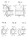
- FIG 10 shows a side view of the curtain application device disclosed in US-A-3,632,374.
- liquid 13 flows out from the interior of a slide hopper 11 to a slide surface 12 thereof, and then freely falls in the form of a thin film from the downstream end 14 of the slide surface to form thin curtain 15, which collides against a moving web 16 so as to be applied thereto.
- the application start plate 18 which is a rectangular flat plate, is in such a position as to prevent the curtain from reaching the web.
- the liquid first flows down onto the application start plate 18 and is gathered into a recovery vessel 21.
- the application start plate 18 is then turned about a fulcrum 19 so that the liquid curtain is allowed to reach the web 16, thus starting the application of the liquid curtain to the web.
- the curtain application device provided in accordance with the present invention, liquid freely falling in the form of a thin curtain from a slide hopper is caused to collide against a web continuously moving around a backup roller so that the liquid is applied to the web.
- the device is characterized by the provision of an application start plate which is curved or bent and which can be turned about a fulcrum located under the backup roller or which is turnable or slidable, and which has an upper end extending at an oblique angle to the direction of width of the curtain, or which has a curtain receiving part at the upper end of the plate.
- a liquid 3 to be applied flows out from the interior of a slide hopper 1 onto the slide surface 2 thereof and then freely falls in the form of a thin curtain 5 from the downstream end 4 of the slide surface.
- the upper end of an application start plate 8 is placed in a position A so as to prevent the curtain from reaching the web.
- the application start plate 8 is curved or bent such that it surrounds a backup roller 7.
- the lower end of the plate 8 is pivotally coupled to a fulcrum 9 under the nearby backup roller 7.
- Both side edges of the curtain 5 are defined by edge guides 10 extending from the downstream end 4 of the slide surface 2 to the vicinity of the upper end of the area where the curtain collides against the moving web 6.
- the fulcrum 9 is located under the backup roller 7, the fulcrum is not confined to such a location but may be such that shafts are provided at the sides of the application device near the axis of rotation of the backup roller to reduce the radius of turning of the application start plate 8. It will be understood that the application device can be also applied to the case where the height of the curtain is made large, due to the ease of generation of the curtain, or the distance between the web and the edge guides is made large.
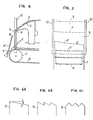
- Figure 4 shows a side view of an application device which is only partially in compliance with the present invention.
- Figure 5 shows a front view of the application device of Figure 4.
- the oblique angle ⁇ of the upper end of the application start plate 8′ relative to the direction of width of the curtain 5 is 1° to 30°, preferably 2° to 10°.
- the upper end of the application start plate 8′ is straight as shown in Figure 6A, the upper end is not confined to such a shape, and it may have a sawtooth shape as shown in Figure 6B or a zigzag shape as shown in Figure 6C, and the constituent lines of the sawtooth-shaped or zigzag-shaped upper end may be either straight or curved.
- the application start plate 8′ may be translated instead of being turned to move the upper end thereof out of the position A′ into the other position B′.
- the application start plate 8" of the device is bent in an L-shape so that the plate has a curtain receiving part at the upper end of the plate.
- the application start plate 8" is turned so that the upper end thereof is moved away from such a position A" so as to prevent the curtain from reaching the web, and is then moved into such a position B" so as to allow the curtain to reach the web.
- the curtain 5 changes from a state of colliding against the application start plate 8" under the curtain receiving part thereof, as shown in Figure 9A, into a state of colliding against the curtain receiving part and falling onto the moving web 6, as shown in Figure 9B.
- the plate 8 is turned further so that the plate is separated from the curtain 5 to allow it to directly reach the moving web 6, as shown in FIgure 9C. Since the curtain 5 is received by the curtain receiving part and then reaches the moving web 6 at the start of the application of the curtain thereto, liquid accumulation is prevented from affecting the thickness of the applied liquid on the web as in the conventional application device described above. The thickness of the initially applied portion of the liquid on the web 6 is thus made much less likely to become larger than that of other portions.
- the width l of the curtain receiving part is 2 mm to 10 mm, preferably 3 mm to 5 mm.
- the angle ⁇ of the part to the horizontal plane is 20° to 90°, preferably 40° to 60°.
- the application device shown in Figures 1 and 2 may be modified so that the curved or bent application start plate 8 has a curtain receiving part at the upper end of the plate, as shown in Figures 7 and 8, so as to cause the curtain 5 to be received by that part and then to fall onto the moving web 6 at the start of the application of the curtain, thereto to prevent an increase in the thickness of the applied liquid onto the web and thus making the surface of the applied liquid flat and smooth.
- the web 6 to which the curtain 5 is applied by each of the above application devices may be paper, a plastic film, a metal sheet, resin-coated paper, synthetic paper or the like.
- the plastic film may be made of a polyolefin such as polyethylene or polystyrene, a vinyl polymer, a polyamide such as 6,6-nylon or 6-nylon, a polyester such as polyethylene terephthalate or polyethylene 2,6-naphthalate, polycarbonate, or a cellulose acetate such as cellulose triacetate or cellulose diacetate.
- the resin for the resin-coated paper may be a polyolefin such as polyethylene.
- the surface of the resincoated paper may be embossed or not. Embossment is not confined to any particular form.
- the metal sheet may be an aluminum sheet, for example.
- the distance between the web and the lower ends of the edge guides 10 was 10 mm.
- the upper end of the application start plate 8 was located at a distance 5 mm up from the web.
- the application start plate 8 was turned downward so that the upper end thereof was moved out of the position A into the other position B. As a result, the curtain was stably applied to the moving web.
- a thin curtain of liquid was applied to a moving web by the application device shown in Figure 3.
- the liquid and the conditions of the application were the same as those in Example 1.
- the slide hopper 1 was moved and the application start plate 8 remained at a standstill.
- the application start plate 8 was turned downward. As a result, the curtain was stably applied to the moving web.
Landscapes
- Chemical & Material Sciences (AREA)
- Engineering & Computer Science (AREA)
- Materials Engineering (AREA)
- Physics & Mathematics (AREA)
- General Physics & Mathematics (AREA)
- Coating Apparatus (AREA)
- Application Of Or Painting With Fluid Materials (AREA)
Claims (4)
- Vorrichtung zum Auftragen einer Flüssigkeit, die frei in Form eines dünnen Vorhangs (5) von einem Behälter auf ein sich fortwährend um eine Andruckrolle (7) bewegendes Band (6) fällt, so daß die Flüssigkeit auf das Band aufgetragen wird, wobei die Vorrichtung eine schwenkbare Platte (8) zum Starten des Auftragens umfaßt,
dadurch gekennzeichnet, daß
die Platte (8) gekrümmt oder gebogen ist, und eine Drehachse (9) zum Verschwenken der Platte unter der Andruckrolle (7) angeordnet ist. - Vorrichtung zum Auftragen einer Flüssigkeit nach Anspruch 1, dadurch gekennzeichnet, daß die Platte (8) ein L-förmiges Vorhangauffangteil an einem oberen Ende der Platte aufweist.
- Vorrichtung zum Auftragen einer Flüssigkeit nach Anspruch 2, dadurch gekennzeichnet, daß die Breite des Vorhangauffangteiles in einem Bereich von 2 mm bis 10 mm liegt.
- Vorrichtung zum Auftragen einer Flüssigkeit nach Anspruch 1, dadurch gekennzeichnet, daß die Startplatte eine oberes Ende aufweist, das sich mit einer oder mehreren flachen Winkellinien zur Richtung der Breite des dünnen aufzutragenden Flüssigkeitsvorhangs erstreckt.
Priority Applications (1)
| Application Number | Priority Date | Filing Date | Title |
|---|---|---|---|
| EP93120296A EP0609535B1 (de) | 1988-06-02 | 1989-05-31 | Vorrichtung zum Auftragen mehrerer Flüssigkeiten |
Applications Claiming Priority (2)
| Application Number | Priority Date | Filing Date | Title |
|---|---|---|---|
| JP135997/88 | 1988-06-02 | ||
| JP63135997A JP2562941B2 (ja) | 1988-06-02 | 1988-06-02 | 塗布装置 |
Related Child Applications (2)
| Application Number | Title | Priority Date | Filing Date |
|---|---|---|---|
| EP93120296A Division EP0609535B1 (de) | 1988-06-02 | 1989-05-31 | Vorrichtung zum Auftragen mehrerer Flüssigkeiten |
| EP93120296.4 Division-Into | 1989-05-31 |
Publications (2)
| Publication Number | Publication Date |
|---|---|
| EP0344745A1 EP0344745A1 (de) | 1989-12-06 |
| EP0344745B1 true EP0344745B1 (de) | 1995-02-01 |
Family
ID=15164781
Family Applications (2)
| Application Number | Title | Priority Date | Filing Date |
|---|---|---|---|
| EP93120296A Expired - Lifetime EP0609535B1 (de) | 1988-06-02 | 1989-05-31 | Vorrichtung zum Auftragen mehrerer Flüssigkeiten |
| EP89109843A Expired - Lifetime EP0344745B1 (de) | 1988-06-02 | 1989-05-31 | Vorrichtung zum Auftragen mehrerer Flüssigkeiten |
Family Applications Before (1)
| Application Number | Title | Priority Date | Filing Date |
|---|---|---|---|
| EP93120296A Expired - Lifetime EP0609535B1 (de) | 1988-06-02 | 1989-05-31 | Vorrichtung zum Auftragen mehrerer Flüssigkeiten |
Country Status (4)
| Country | Link |
|---|---|
| US (1) | US4922851A (de) |
| EP (2) | EP0609535B1 (de) |
| JP (1) | JP2562941B2 (de) |
| DE (2) | DE68920911T2 (de) |
Families Citing this family (21)
| Publication number | Priority date | Publication date | Assignee | Title |
|---|---|---|---|---|
| JPH02216139A (ja) | 1989-02-17 | 1990-08-29 | Konica Corp | 写真感光材料の製造方法 |
| US5136970A (en) * | 1989-10-06 | 1992-08-11 | Fuji Photo Film Co., Ltd. | Coating apparatus with vertically movable solution receiver |
| JP2849836B2 (ja) * | 1989-10-31 | 1999-01-27 | 富士写真フイルム株式会社 | 塗布方法 |
| JPH0642771Y2 (ja) * | 1990-02-17 | 1994-11-09 | 新日本製鐵株式会社 | カーテンコーターにおけるカーテン受け装置 |
| JP2520769B2 (ja) * | 1990-06-28 | 1996-07-31 | 富士写真フイルム株式会社 | カ―テン塗布方法及び装置 |
| JP2533812B2 (ja) * | 1990-07-13 | 1996-09-11 | 富士写真フイルム株式会社 | ガラス乾板製造方法及び装置 |
| US5105758A (en) * | 1990-08-08 | 1992-04-21 | Eastman Kodak Company | Catch pan for use in curtain coating apparatus |
| US5017408A (en) * | 1990-08-08 | 1991-05-21 | Eastman Kodak Company | Curtain coating start/finish method and apparatus |
| DE69115470T2 (de) * | 1991-06-18 | 1996-08-01 | Agfa Gevaert Nv | Vorhangbeschichter |
| DE59208321D1 (de) * | 1991-11-13 | 1997-05-15 | Ciba Geigy Ag | Beschichtungsvorrichtung für Platten |
| US5399385A (en) * | 1993-06-07 | 1995-03-21 | Eastman Kodak Company | Curtain coater slide hopper with improved transition profile and method |
| JP3549075B2 (ja) * | 1995-06-02 | 2004-08-04 | 三菱製紙株式会社 | カーテン塗布装置及び塗布方法 |
| JP3621204B2 (ja) * | 1996-08-20 | 2005-02-16 | 三菱製紙株式会社 | カーテン塗布装置及び塗布方法 |
| ATE257949T1 (de) * | 1996-10-09 | 2004-01-15 | Fuji Photo Film Co Ltd | Vorhangsbeschichtungsverfahren |
| JP3563560B2 (ja) * | 1997-05-28 | 2004-09-08 | 三菱製紙株式会社 | カーテン塗布装置及び塗布方法 |
| US6602382B1 (en) * | 1999-10-26 | 2003-08-05 | Tokyo Electron Limited | Solution processing apparatus |
| US6346299B1 (en) | 2000-09-13 | 2002-02-12 | Eastman Kodak Company | Method and apparatus for improving the uniformity of a liquid curtain in a curtain coating system-curtain formation/correction |
| FI111562B (fi) | 2002-01-16 | 2003-08-15 | Metso Paper Inc | Menetelmä ja laitteisto käsittelyaineen syöttämiseksi liikkuvalle pinnalle |
| DE102007000776A1 (de) | 2007-09-27 | 2009-04-02 | Voith Patent Gmbh | Auftragsvorrichtung |
| US8789492B2 (en) * | 2008-07-15 | 2014-07-29 | Awi Licensing Company | Coating apparatus and method |
| DE102009023403A1 (de) * | 2009-05-29 | 2010-12-02 | Fraunhofer-Gesellschaft zur Förderung der angewandten Forschung e.V. | Verfahren zur strukturierten Beschichtung von Substraten |
Citations (1)
| Publication number | Priority date | Publication date | Assignee | Title |
|---|---|---|---|---|
| EP0400055A1 (de) * | 1988-01-29 | 1990-12-05 | Eastman Kodak Co | Verfahren zum vorhangbeschichtungsstart und vorrichtung. |
Family Cites Families (13)
| Publication number | Priority date | Publication date | Assignee | Title |
|---|---|---|---|---|
| US3434457A (en) * | 1966-01-10 | 1969-03-25 | Ashdee Corp | Coating equipment accessory |
| US3867901A (en) * | 1968-06-03 | 1975-02-25 | Eastman Kodak Co | Apparatus for production of photographic elements |
| US3508947A (en) * | 1968-06-03 | 1970-04-28 | Eastman Kodak Co | Method for simultaneously applying a plurality of coated layers by forming a stable multilayer free-falling vertical curtain |
| US3632374A (en) * | 1968-06-03 | 1972-01-04 | Eastman Kodak Co | Method of making photographic elements |
| GB1429260A (en) * | 1973-10-12 | 1976-03-24 | Ciba Geigy Ag | Coating apparatus |
| US3958532A (en) * | 1974-07-22 | 1976-05-25 | Polaroid Corporation | Coating apparatus |
| GB1559701A (en) * | 1976-05-26 | 1980-01-23 | Ciba Geigy Ag | Curtain coating |
| CH626817A5 (de) * | 1977-09-12 | 1981-12-15 | Ciba Geigy Ag | |
| DE2962311D1 (en) * | 1978-03-01 | 1982-04-29 | Agfa Gevaert Nv | Method for applying a plurality of superposed photographic layers to a web by curtain coating |
| CA1140001A (en) * | 1979-04-19 | 1983-01-25 | Karel S. Willemsens | Method and device for slide hopper multilayer coating |
| DE3241831A1 (de) * | 1982-11-12 | 1984-05-17 | Agfa-Gevaert Ag, 5090 Leverkusen | Verfahren und vorrichtung zur erzeugung der breite oder der streifenbreite von beschichtungen auf bahnen |
| DE3300150A1 (de) * | 1983-01-04 | 1984-07-05 | Agfa-Gevaert Ag, 5090 Leverkusen | Verfahren und vorrichtung zur stabilisierung von frei fallenden fluessigkeitsvorhaengen |
| DE3424884C1 (de) * | 1984-07-06 | 1986-02-20 | Du Pont de Nemours (Deutschland) GmbH, 4000 Düsseldorf | Vorrichtung zum Auftragen mindestens einer Giessschicht und Verfahren zum Betrieb dieser Vorrichtung |
-
1988
- 1988-06-02 JP JP63135997A patent/JP2562941B2/ja not_active Expired - Lifetime
-
1989
- 1989-05-31 DE DE68920911T patent/DE68920911T2/de not_active Expired - Lifetime
- 1989-05-31 EP EP93120296A patent/EP0609535B1/de not_active Expired - Lifetime
- 1989-05-31 DE DE68929143T patent/DE68929143T2/de not_active Expired - Lifetime
- 1989-05-31 EP EP89109843A patent/EP0344745B1/de not_active Expired - Lifetime
- 1989-06-02 US US07/360,635 patent/US4922851A/en not_active Expired - Lifetime
Patent Citations (1)
| Publication number | Priority date | Publication date | Assignee | Title |
|---|---|---|---|---|
| EP0400055A1 (de) * | 1988-01-29 | 1990-12-05 | Eastman Kodak Co | Verfahren zum vorhangbeschichtungsstart und vorrichtung. |
Also Published As
| Publication number | Publication date |
|---|---|
| JP2562941B2 (ja) | 1996-12-11 |
| US4922851A (en) | 1990-05-08 |
| EP0609535B1 (de) | 2000-01-19 |
| EP0609535A3 (de) | 1997-07-30 |
| EP0609535A2 (de) | 1994-08-10 |
| EP0344745A1 (de) | 1989-12-06 |
| DE68920911T2 (de) | 1995-05-24 |
| DE68929143T2 (de) | 2000-06-15 |
| DE68920911D1 (de) | 1995-03-16 |
| DE68929143D1 (de) | 2000-02-24 |
| JPH01304076A (ja) | 1989-12-07 |
Similar Documents
| Publication | Publication Date | Title |
|---|---|---|
| EP0344745B1 (de) | Vorrichtung zum Auftragen mehrerer Flüssigkeiten | |
| EP0329802B1 (de) | Mehrfachbeschichtungsverfahren | |
| JPH0339294B2 (de) | ||
| EP0327020A2 (de) | Beschichtungsvorrichtung | |
| US4440811A (en) | Method for coating and an apparatus for coating | |
| EP0897326B1 (de) | Beschichtungsanordnung und darin enthaltene einfassung | |
| EP0974403B1 (de) | Beschichtungsverfahren und -vorrichtung | |
| JP2575579B2 (ja) | スライドビードコーティング装置および写真用部材形成方法 | |
| JPH074568B2 (ja) | 塗布方法 | |
| KR20000070307A (ko) | 다이 에지 세척 시스템 | |
| JPH0566193B2 (de) | ||
| AU626316B2 (en) | Curtain coating method and apparatus | |
| JP2782531B2 (ja) | カーテン塗布の塗布巾変更装置 | |
| US5413818A (en) | Curtain coating method and apparatus utilizing checking plate for controlling liquid flow | |
| US20020026895A1 (en) | Coating apparatus for a traveling web | |
| JP2534123B2 (ja) | 塗布装置 | |
| EP0822007A2 (de) | Verfahren und Vorrichtung zum Starten einer Beschichtung eines Substrates das sich mit hoher Geschwindigkeit bewegt | |
| JPH067815Y2 (ja) | 塗布装置 | |
| JPH0433985Y2 (de) | ||
| JPH0135253Y2 (de) | ||
| JP2715353B2 (ja) | 塗布方法 | |
| JPS6135880A (ja) | 塗布装置 | |
| JPH0759310B2 (ja) | 塗布方法及び装置 | |
| JP3713939B2 (ja) | 多層画像形成基材の製造方法 | |
| JPH02277570A (ja) | 塗布装置 |
Legal Events
| Date | Code | Title | Description |
|---|---|---|---|
| PUAI | Public reference made under article 153(3) epc to a published international application that has entered the european phase |
Free format text: ORIGINAL CODE: 0009012 |
|
| AK | Designated contracting states |
Kind code of ref document: A1 Designated state(s): DE NL |
|
| 17P | Request for examination filed |
Effective date: 19900528 |
|
| 17Q | First examination report despatched |
Effective date: 19930528 |
|
| GRAA | (expected) grant |
Free format text: ORIGINAL CODE: 0009210 |
|
| AK | Designated contracting states |
Kind code of ref document: B1 Designated state(s): DE NL |
|
| XX | Miscellaneous (additional remarks) |
Free format text: TEILANMELDUNG 93120296.4 EINGEREICHT AM 31/05/89. |
|
| REF | Corresponds to: |
Ref document number: 68920911 Country of ref document: DE Date of ref document: 19950316 |
|
| PLBE | No opposition filed within time limit |
Free format text: ORIGINAL CODE: 0009261 |
|
| STAA | Information on the status of an ep patent application or granted ep patent |
Free format text: STATUS: NO OPPOSITION FILED WITHIN TIME LIMIT |
|
| 26N | No opposition filed | ||
| PGFP | Annual fee paid to national office [announced via postgrant information from national office to epo] |
Ref country code: DE Payment date: 20080605 Year of fee payment: 20 |
|
| PGFP | Annual fee paid to national office [announced via postgrant information from national office to epo] |
Ref country code: NL Payment date: 20080501 Year of fee payment: 20 |
|
| PG25 | Lapsed in a contracting state [announced via postgrant information from national office to epo] |
Ref country code: NL Free format text: LAPSE BECAUSE OF EXPIRATION OF PROTECTION Effective date: 20090531 |
|
| NLV7 | Nl: ceased due to reaching the maximum lifetime of a patent |
Effective date: 20090531 |