EP0897326B1 - Beschichtungsanordnung und darin enthaltene einfassung - Google Patents
Beschichtungsanordnung und darin enthaltene einfassung Download PDFInfo
- Publication number
- EP0897326B1 EP0897326B1 EP97921286A EP97921286A EP0897326B1 EP 0897326 B1 EP0897326 B1 EP 0897326B1 EP 97921286 A EP97921286 A EP 97921286A EP 97921286 A EP97921286 A EP 97921286A EP 0897326 B1 EP0897326 B1 EP 0897326B1
- Authority
- EP
- European Patent Office
- Prior art keywords
- coating
- coater
- coating apparatus
- enclosure
- fluid
- Prior art date
- Legal status (The legal status is an assumption and is not a legal conclusion. Google has not performed a legal analysis and makes no representation as to the accuracy of the status listed.)
- Expired - Lifetime
Links
Images


Classifications
-
- B—PERFORMING OPERATIONS; TRANSPORTING
- B05—SPRAYING OR ATOMISING IN GENERAL; APPLYING FLUENT MATERIALS TO SURFACES, IN GENERAL
- B05C—APPARATUS FOR APPLYING FLUENT MATERIALS TO SURFACES, IN GENERAL
- B05C5/00—Apparatus in which liquid or other fluent material is projected, poured or allowed to flow on to the surface of the work
- B05C5/007—Slide-hopper coaters, i.e. apparatus in which the liquid or other fluent material flows freely on an inclined surface before contacting the work
- B05C5/008—Slide-hopper curtain coaters
-
- Y—GENERAL TAGGING OF NEW TECHNOLOGICAL DEVELOPMENTS; GENERAL TAGGING OF CROSS-SECTIONAL TECHNOLOGIES SPANNING OVER SEVERAL SECTIONS OF THE IPC; TECHNICAL SUBJECTS COVERED BY FORMER USPC CROSS-REFERENCE ART COLLECTIONS [XRACs] AND DIGESTS
- Y10—TECHNICAL SUBJECTS COVERED BY FORMER USPC
- Y10S—TECHNICAL SUBJECTS COVERED BY FORMER USPC CROSS-REFERENCE ART COLLECTIONS [XRACs] AND DIGESTS
- Y10S118/00—Coating apparatus
- Y10S118/04—Curtain coater
Definitions
- Die coating methods such as slide coating and curtain coating are useful methods by which a fluid can be coated onto a moving web.
- the fluid flows from a slide or curtain coating apparatus, the fluid contacts the coating apparatus at one or more surfaces.
- the interface between a surface of the coating apparatus and the coating fluid can create a condition of zero or nearly zero flow of the fluid at the surface of the coating apparatus.
- the interface can be referred to as a static contact line.
- the static contact line is exposed to the atmosphere above (e.g., air)
- the solvent in the coating fluid has an opportunity to evaporate from the fluid, and the fluid can dry, leaving behind a build-up of dried coating material at the static contact line.
- the buildup of dried coating material can continue to grow over time and cause complications in the coating process.
- Static contact lines can occur, for example, at the interface between a flowing coating fluid and an edge guide. At the edge guides, the drying of the coating fluid and a buildup of dried coating material can result in unstable or starved flow of the coating fluid at the edges, leading to breaking of the coating bead at the edges, narrowing of the coated width, crossweb nonuniformity of the coated fluid, for example heavier or lower coating weights at the edges, etc.
- a second location where static contact lines can occur is at or near a feed slot. Drying of the coating fluid at static contact lines that is adjacent to a feed slot can result in streaking defects in the coating, or nonuniform coating thickness.
- US-A-4 287 240 describes a coating apparatus for carrying out a process of coating a composition to a surface of an object.
- This object e.g., a continuous web
- This object is advanced through a coating zone in which a flow of coating composition is applied thereto by a bead coating or curtain coating apparatus.
- a shield is provided to protect the flow of coating composition against disturbance by ambient air currents.
- the shield is formed of a foraminous material such as screening or perforated plate material, which functions to diffuse air currents impinging thereon so that their velocity is decreased, with a resulting decrease in their ability to disturb the flow of coating composition.
- the shield structure is pivotally affixed so as to enable it to be swung into position to protect the flow of coating composition during use and to be swung up and out of the way to provide access for purposes such as cleaning and maintenance.
- WO-A-90/01178 relates to a coating apparatus for applying a coating of coating composition to a surface of a continuous web or discrete sections of sheet material.
- the apparatus includes a cascade slide hopper to supply coating composition to the coating zone.
- the coating compositions flowing down the slide surfaces of the cascade slide hopper are protected from adverse effects of convection air currents by a shield which is positioned so close to the slide surfaces of the cascade slide hopper as to prevent the creation of thermal connection currents.
- this shield is heated to a temperature equal to or above the temperature of the coating compositions to prevent condensation.
- US-A-4 292 349 relates to an apparatus and method for applying a high volatility liquid to a moving web to form a coating on the web.
- the coating liquid is applied to the web through an extrusion-type or slide-type hopper covered by a hood which collects evaporated gas from the applied solvent at a region at which a solid-, liquid-, and gas-phase interface of the coating liquid is formed.
- DE-A-31 10 821 relates to a coating device, particularly for applying photographic liquids to a carrier material or a substrate, comprising at least one first forming tool with a surface which lies in a plane perpendicular both to the carrier material on which the coating liquid is to be applied and also to the direction of action of gravity.
- the coating liquid flows onto the surface of the forming tool only by virtue of the force of its own surface tension.
- Past attempts to solve the problems caused by static contact lines include providing enclosures that completely surround a coating apparatus. However, it can be important to have both clear visibility and free access to a coating apparatus, and the fluid flowing thereover, to identify where a coating problem exists and to be readily able to correct the problem. Enclosures that completely surround a coating apparatus prevent access to and visibility of the coating fluid at all portions of the coating apparatus, not only the static contact lines. Therefore, what is needed but not provided by the prior art is a means for preventing or reducing premature drying of a coating fluid at static contact lines, while also allowing visibility of, and access to, the remaining portion of the coater face, and the fluid that flows from the die coating apparatus. This used is met with the features of the claims.
- the present invention provides a coating assembly with a coating apparatus and an enclosure, the coating apparatus being of the type generally comprising a coater face adapted for the flow of a fluid.
- the fluid will flow over the coater face in the form of a film having one or more edges that will contact the coating apparatus at one or more surfaces ("edge contact surfaces").
- the enclosure of the present invention defines a partially enclosed space above one or more of the edge contact surfaces.
- the atmosphere within the partially enclosed space can be at least partially saturated with solvent vapor to prevent or inhibit drying of the coating fluid at the edge contact surfaces.
- the present invention can reduce or eliminate problems caused by premature drying of a coating fluid on the coating apparatus.
- the enclosure has a shape that allows visibility of, and access to, a substantial portion of the coater face of the coating apparatus, and/or the coating fluid flowing from the coating apparatus.
- Another aspect of the present invention is a method of coating a fluid onto a substrate.
- the method includes the steps of providing a coater assembly comprising a coating apparatus and the above-described enclosure; providing a coating fluid flowing from the coating apparatus; and coating the fluid onto a substrate.
- edge contact surface refers to the line or surface of a coating apparatus that approximately corresponds to the location where the edge of a coating fluid would contact a surface of the coating apparatus if a coating fluid were flowing from the coating apparatus.
- static contact line refers to the actual line or surface defined approximately by the three-way interface between a coating fluid, a surface of a coating apparatus, and the atmosphere above. The relationship between an edge contact surface and a static contact line is that an edge contact surface is located on a surface of a coating apparatus at the position where a static contact line would exist upon introduction of a coating fluid to the coating apparatus.
- the enclosure used with the present invention can be used in combination with coating apparatuses that are susceptible to the formation of static contact lines.
- These coating apparatuses generally comprise a coater face that is adapted for the flow of a coating fluid in the form of a film having one or more edges.
- the locations where edges of a coating fluid film flowing over the coater face would contact the coating apparatus are referred to as "edge contact surfaces.”
- An edge contact surface can exist, for example, where a coating fluid would contact a surface of a coater apparatus upon being introduced to the coating apparatus, for example at or adjacent to a feed slot.
- one or more edge contact surfaces will exist along the length of a coater face (in the direction of flow of the coating fluid) where the edge of a coating fluid film flowing down the coater face would contact a surface of the coating apparatus.
- the coating apparatus comprises one or more edge guides along the length of the coater face to provide better control of the coating fluid film flowing down the coater face.
- the coating fluid film contacts the with edge guides, facilitating uniform flow of the fluid down the coater face the coating apparatus comprising edge guides, edge contact surfaces exist where a coating fluid film flowing past the edge guides contacts the edge guides.
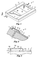
- FIG. 1 illustrates an example of a slide coating apparatus suitable for use with the enclosure.
- Slide coating apparatus 2 includes coater face 4 and edge guides 12. Coating fluid 8 flows from feed slot 6 and down coater face 4 as a film, preferably a continuous film. The edges of the coating fluid film contact surfaces of edge guides 12, creating static contact lines 10 at the interface where coating fluid 8 and edge guides 12 are exposed to the atmosphere above. Static contact line 16 exists adjacent to feed slot 6, where the interface between coating fluid 8 and coater face 4 is exposed to the atmosphere above.
- slide coating apparatus 2 includes one or more additional feed slots 22 along coater face 4. These additional feed slots will feed fluid underneath the coating fluid film flowing down coater face 4 from feed slot 6 (the uppermost feed slot), and therefore, the additional feed slots will not be the cause of additional static contact lines.
- FIG. 6 illustrates an example of a curtain coating apparatus suitable for use with the enclosure of present invention.
- Curtain coating apparatus 30 includes coater face 34 having feed slot 32. Coating fluid 8 flows from feed slot 32, down coater face 34, over front edge 33, and then falls as liquid curtain 38 to a substrate below.
- Static contact line 36 is created adjacent to feed slot 32, at the exposed interface between coating fluid 8 and coater face 34.
- Static contact lines 37 are created at the interface between an edge of coating fluid 8 and coater face 34.
- a static contact line also forms at front edge 33.
- Static contact lines 39 are created at the interface between liquid curtain 38 and edge guides 40.
- the coating fluid can be any fluid that contains a solid component and a solvent component, wherein the solvent component can evaporate from the fluid to leave behind the solid component.
- the coating fluid can be a solvent-based solution, a water-based solution, or a dispersion.
- the coating fluid can be any of the fluids commonly coated as an adhesive, a latex, paint, an element or layer of a photosensitive material such as a photographic or photothermographic material, a magnetic or nonmagnetic layer of a magnetic medium etc.
- the coating fluid can be of a composition that can be cured, solidified or crosslinked after being coated, for example by exposure to heat or radiation.
- the solid component of the coating fluid can be any material that is useful, for example, as an adhesive, as a component or element of a photographic, thermographic, or photothermographic material, an element or layer of a magnetic recording medium, dyes, radiation-curable materials, abrasive or microabrasive materials, etc.
- the solvent component can be water or any organic solvent known to be useful in the coating arts, including methyl ethyl ketone (MEK), toluene, tetrahydrofuran (THF), methyl isobutyl ketone (MIBK), or mixtures thereof. Coating complications of the type relating to static contact lines tend to increase when highly volatile solvents are used in the coating fluid. Therefore, the present invention has particular utility when solvents such as MEK, toluene, or acetone are used within a coating fluid.
- the coating fluid can be of any viscosity that allows the fluid to be coated by die coating methods such as curtain and slide coating methods, and can be dependent upon the particular application of the coating fluid.
- the complications caused by static contact lines generally tend to increase with viscosity of a coating fluid because relatively higher viscosity fluids flow more slowly, increasing the potential for premature drying at a static contact line.
- Preferred coating fluids often used in slide and curtain coating systems include water-based solutions, emulsions, dispersions, or gels such as those known to be useful in imaging elements such as photographic film, x-ray film, graphic arts film, etc.
- the solid component of these coating fluids typically includes a binder such as, for example, gelatin, polyvinyl alcohol, or an aqueous film-forming latex, and can often include other known and useful ingredients such as radiation-sensitive materials (e.g., silver halide compounds) matting agents, sensitizers, hardeners, etc.
- the solvent for these elements is typically water although small amounts of organic solvents may also be present.
- Preferred coating fluids often used in slide and curtain coating systems also include organic solvent-based solutions, emulsions, dispersions, or gels such as those known to be useful photothermographic, and thermographic imaging elements, photoresists and photopolymers.
- the solid component of these coating fluids typically includes a binder such as, for example, polyvinyl acetal, polyvinyl acetate, and polyvinyl chloride; and can also often include other known and useful ingredients such as light-sensitive materials (e.g., silver halide compounds) matting agents, sensitizers, hardeners, etc.
- the solvent for these elements is typically an organic solvent such methyl ethyl ketone (2-butanone, MEK), toluene, methanol, or mixtures thereof.
- organic solvent such methyl ethyl ketone (2-butanone, MEK), toluene, methanol, or mixtures thereof.
- the interface between a coating fluid and a surface of a coating apparatus can create what is known as a static contact condition.
- a static contact condition e.g., a coater face surface or a surface of an edge guide
- this static contact condition is referred to as a static contact line.
- static contact tines are illustrated in the Figures.
- Figures 1 and 2 illustrate static contact line 16 adjacent to feed slot 6.
- Figures 3 and 4 illustrate static contact line 10 at the interface between coating fluid 8 and edge guide 12.
- FIG. 6 illustrates the existence of static contact lines on a curtain coating apparatus: specifically, Figure 6 illustrates static contact line 36 where coating fluid 8 contacts coater face 34 adjacent to feed slot 32; static contact lines 37 at the interface between an edge of coating fluid 8 and coater face 34; static contact lines 39 at the interface of an edge of curtain 38 and edge guides 40; and a static contact line that exists at the interface between front edge 33 and coating fluid 8.
- Coater face 34 is fitted with edge guides such as edge guides 12 in Figure 1, creating static contact lines at the interface between an edge of coating fluid 8 and the edge guides (this situation would be similar to the creation of static contact lines 10 as illustrated in Figures 1 and 2).
- the solvent component of the coating fluid can tend to evaporate into the atmosphere above the static contact line, if that atmosphere is not saturated or partially saturated with solvent of the same or similar composition as the solvent component of the coating fluid.
- the solvent component of the coating fluid evaporates, solids from the coating fluid remain behind and can accumulate on the surface of the coating apparatus as a mass of highly viscous material or dried coating solids.
- the accumulation of highly viscous material or dried coating solids on the surface of a coating apparatus can potentially cause complications in the coating process, as well as defects in a coated product produced using such an apparatus. Examples of defects include streaks, non-coated areas of the substrate, particles or agglomerations in the coating, areas of nonuniform coating thickness, etc.
- the enclosure inhibits or prevents evaporation of solvent from a coating fluid at a static contact line, thereby inhibiting or preventing drying of the coating fluid, and reducing or preventing complications caused by such drying.
- the enclosure prevents or inhibits evaporation of solvent from the coating fluid by defining a partially enclosed space above a static contact line, thereby allowing control of the solvent vapor compositions of the atmosphere above the static contact line.
- the atmosphere within this partially enclosed space (the "atmosphere") generally comprises air or an inert gas such as argon, nitrogen, or carbon dioxide.
- solvent vapor can be introduced into the atmosphere, either as pure solvent vapor or as a solvent vapor-containing gas which can be either saturated or partially saturated with the solvent vapor. Maintaining a desired concentration of the solvent vapor within this atmosphere can inhibit or prevent evaporation of solvent from the coating fluid into the atmosphere.
- the composition of the solvent vapor can be chosen to be sufficiently similar to the solvent component of the coating fluid that partial or complete saturation of the atmosphere above the coating fluid, with the solvent vapor, will inhibit or prevent evaporation of solvent from the coating fluid into the atmosphere, thus preventing drying of the coating fluid.
- the solvent component is water
- the atmosphere should contain water vapor in an amount sufficient to inhibit or prevent a net flow of water from the coating fluid into the atmosphere.
- the amount of solvent vapor present in the atmosphere can be chosen depending on several factors, including the chemical composition and volatility of the solvent vapor, the composition of the coating fluid, the composition of other components of the atmosphere, and the temperature.
- the atmosphere is saturated with solvent vapor.
- saturated it is meant that the gaseous atmosphere would be unable to contain any more solvent vapor, at a given temperature and pressure, without solvent condensing from the atmosphere.
- the enclosure can be of any design that will allow control of the composition of the atmosphere above a static contact line.
- the enclosure is shaped to fit over a slide or curtain coating apparatus in a fashion that defines a partially enclosed space above a static contact line, allowing control of the solvent vapor composition as well as solvent vapor flow within that space.
- the enclosure when viewed as a side section as in Figures 2, 3 and 4, can be flat, curved, bent or cornered at any angle, or of any other shape that can be used to create a partially enclosed space over a static contact line.
- the enclosure can be made of one or more pieces that can be attached or fitted together and to a coating apparatus.
- a side view of a slide coater feed slot is illustrated in Figure 2, showing enclosure 18 adapted to slide coating apparatus 2 near static contact line 16.
- a first portion 11 of enclosure 18 contacts face 4 of coating apparatus 2.
- a second portion 13 of enclosure 18 extends away from coating apparatus 2.
- a third portion 15 of enclosure 18 extends over static contact line 16, and a bent lip 17 extends back toward the coating apparatus above the coating fluid, the enclosure creating a partially enclosed space above the static contact line.
- extension 21 extends from the bottom of enclosure 18B near edge guide 12. Extension 21 allows further control of the flow of solvent vapor over static contact line 10 by providing a precision slot from for metering the flow of the solvent containing gas.
- a small gap 19 exists between bent lip 17 and coating fluid 8 through which vapor can escape.
- the partially enclosed space is preferably as small as possible without coating fluid 8 contacting enclosure 18, e.g., at bent lip 17.
- Solvent vapor can be provided to the partially enclosed space defined by enclosure 18 by any suitable method.
- solvent vapor can evaporate out of coating fluid 8 and accumulate in the partially enclosed space, creating an atmosphere above a static contact line that is saturated or partially saturated with solvent vapor.
- coating fluid 8 flows from feed slot 6, some amount of the solvent component of coating fluid 8 evaporates into the atmosphere above coating fluid 8.
- the evaporated solvent accumulates within the partially enclosed space defined by enclosure 18, and the atmosphere within this space becomes at least partially saturated, and preferably fully saturated, with the solvent vapor. Further evaporation of solvent from coating fluid 8 will be inhibited, and premature drying of coating fluid 8 at static contact line 16 will be reduced or prevented.
- solvent vapor can be supplied to the partially enclosed space defined by enclosure 18 from an outside source.
- solvent vapor in the form of a solvent vapor-containing gas can be provided under enclosure 18A through passage 20 in portion 13A.
- a separate device (not shown) can supply a solvent vapor-containing gas through passage 20 to the partially enclosed space.
- the solvent vapor-containing gas provided from an outside source can be pure solvent vapor, or can comprise a gas that is partially saturated, and preferably completely saturated, with solvent vapor.
- the gas can be air, or an inert or non-reactive gas such as nitrogen, argon, or carbon dioxide.
- the solvent vapor-containing gas is preferably provided to the partially enclosed space at a regulated pressure, in an adequate volume, and at a rate that will maintain solvent vapor saturation of the atmosphere within the space, and maintain a constant positive flow out of the partially enclosed space.
- the flow rate of the solvent vapor-containing gas is preferably the minimum required to inhibit or prevent evaporation of solvent from the coating fluid.
- An appropriate flow rate for the solvent vapor-containing gas will depend on the concentration of solvent vapor in the gas, which can in turn depend on the identity of the solvent vapor, the solvent containing gas, and temperature. For saturated gases, flow rates that have been found to be useful are in the range from about 0 to 3200 cubic centimeters (cm 3 )/minute per lineal centimeter of static contact line, with preferred flow rates being in the range from about 400 to 2400 cm 3 /min per lineal cm of static contact line.
- An inert, non-reactive gas for use as the solvent vapor-containing gas can be supplied from a tank, optionally through a regulator, or by any other means such as conventional membrane separator technology for nitrogen, combustion for carbon dioxide, or a liquid nitrogen evaporator.
- Methods of producing and supplying a solvent vapor saturated gas are known in the art. Useful methods include those that use saturating devices such as a packed column, a wick, a sparger in a jacketed vessel, or a heat exchanger. These methods are described, for example, in Assignee's copending U.S. Patent Application Serial No. 08/177,288 (filed January 4, 1994) to Yapel et al., said disclosure being incorporated herein by reference.
- the enclosure can be made of any material that can act as a barrier for solvent vapor.
- the enclosure can be made, for example, of materials including plastics or thermoplastics, polymeric materials such as teflon, nylon, polyacrylates, or polycarbonates such as Lexan TM that can optionally be transparent; cardboard; metals; wood; ceramic; or any other material that can act as a barrier to the flow of solvent vapor having a composition of the solvent component of the coating fluid.
- FIG. 5 illustrates a slide coater assembly comprising slide coating apparatus 2 having enclosure 18A fitted thereon.
- enclosure 18A is an essentially "C"-shaped article that defines a partially enclosed space over static contact lines existing at the uppermost feed slot, and at edge guides of slide coating apparatus 2.
- enclosure 18A does not inhibit visual or physical access to a substantial portion of the coating fluid or the coater face, i.e., the portion not located immediately adjacent to an edge guide or the uppermost feed slot.
- a "substantial portion" of the coating fluid or coater face is considered to be at least about 50%, preferably over 75%, for example 85% or 95% of the total area of the coating fluid or coater face.
- FIG 7 illustrates another embodiment of the present invention.
- the curtain coater assembly illustrated in Figure 7 comprises curtain coating apparatus 30 having enclosure 18C fitted thereon, and enclosing the static contact lines present on curtain coating apparatus 30 (shown in Figure 6).
- enclosure 18C has an upper "C"-shaped portion 42 that encloses static contact lines existing between coating fluid 8 and coater face 34.
- enclosure 18C includes two vertical portions 44 that enclose static contact lines 39 existing between the edges of falling curtain 38 and edge guides 40 (see Figure 6).
- Vertical portions 44 can be any shape capable of creating a partially enclosed space around static contact lines 39, without disrupting falling curtain 38.
- vertical portions 44 do not contact falling curtain 38.
- vertical portions 44 can be circular members having a lengthwise slot provided to fit around falling curtain 38.
- a further component of the enclosure (not shown) can be fitted behind curtain 38 and under front edge 33, to enclose the static contact line associated with front edge 33.
- Enclosure 18C controls the solvent vapor composition within the space above static contact lines 36 and 37, and around static contact lines 39 existing on curtain coating apparatus 30. While enclosure 18C encloses these static contact lines, it at the same time allows visibility and access to a substantial portion of coating fluid 8 flowing over coater face 34, and falling as curtain 38 from curtain coating apparatus 30 An operator of this coater assembly could observe and determine the source of any disruption in the coating fluid flow, such as a clogged feed slot or a particle or dried coating material caught at front edge 33 of curtain coating apparatus 30. Furthermore, after observing and determining the cause of the flow disruption, the operator could thereafter remove the cause of the disruption without having to remove the enclosure or stop the coating line.
- the enclosures be designed to be readily retractable or removable and repositionable so as to provide access to the static contact lines between and during coating operations. This might be provided, for instance, by a hinged arrangement.
Landscapes
- Coating Apparatus (AREA)
Claims (8)
- Beschichtungsanordnung, aufweisend eine Beschichtungsvorrichtung (2; 30) und eine Einfassung (18; 18A; 18B; 18C);
wobei die Beschichtungsvorrichtung (2; 30) eine Beschichtungsseite (4; 34) mit einem Zuführschlitz (6; 32) und einer oder mehreren Kantenführungen (12; 40) aufweist, wobei die Beschichtungsseite (4; 34) für den Fluss eines Fluids (8; 38) darüber in Form eines Films ausgelegt ist, wobei der Film eine oder mehrere Kanten aufweist, welche die Beschichtungsvorrichtung (2; 30) an einer oder mehreren Kantenführungen (12; 40) berühren;
wobei die Einfassung (18; 18A; 18B; 18C) und die Beschichtungsvorrichtung (2; 30) einen teilweise umschlossenen Raum über einer oder mehreren der Kantenführungen (12; 40) definieren, wobei die Einfassung (18; 18A; 18B; 18C) eine Form aufweist, die eine Sichtbarkeit von und Zugang zu wenigstens 50% der gesamten Fläche der Beschichtungsseite (4; 34) gestattet, wenn die Einfassung (18; 18A; 18B; 18C) und die Beschichtungsvorrichtung (2; 30) den teilweise umschlossenen Raum über einer oder mehreren der Kantenführungen (12; 40) definieren. - Beschichtungsanordnung nach Anspruch 1, wobei die Einfassung (18; 18A) aufweist:einen ersten Abschnitt (11; 11A), der eine Fläche der Beschichtungsvorrichtung (2) berührt;einen zweiten Abschnitt (13; 13A), der sich von der Beschichtungsvorrichtung (2) weg erstreckt; undeinen dritten Abschnitt (15; 15A), der sich über eine Kanten-Berührungsfläche (16; 10) der Beschichtungsvorrichtung (2) erstreckt.
- Beschichtungsanordnung nach Anspruch 2, wobei die Einfassung (18; 18A) des Weiteren einen gebogenen Lippenabschnitt (17; 17A) aufweist, der sich von dem dritten Abschnitt (15; 15A) zu der Beschichtungsvorrichtung (2) hin erstreckt.
- Beschichtungsanordnung nach Anspruch 3, wobei der zweite Abschnitt (13A) eine Durchführung (20) enthält, durch die ein Gas fließen kann.
- Beschichtungsanordnung nach Anspruch 1, wobei die Beschichtungsvorrichtung (2) eine Gleit-Beschichtungsvorrichtung aufweist, wobei die Beschichtungsseite (4) eine Gleit-Beschichtungsseite (4) mit einem oder mehreren Zuführschlitzen (6, 22) mit einem obersten Zuführschlitz (6) aufweist; wobei sich die Kantenführungen (12) an einer oder mehreren Kanten der Beschichtungsseite (4) befinden; und wobei eine statische Berührungslinie (16) an der Berührungsstelle zwischen dem Beschichtungsfluid (8) und der an den obersten Zuführschlitz (6) angrenzenden Beschichtungsseite (4) vorhanden ist, und eine oder mehrere statische Berührungslinien (16) an der Berührungsstelle zwischen dem Beschichtungsfluid (8) und einer oder mehreren der Kantenführungen (12) vorhanden sind.
- Beschichtungsanordnung nach Anspruch 1, wobei die Beschichtungsvorrichtung (30) eine Streich-Beschichtungsvorrichtung aufweist, wobei die Beschichtungsseite (34) einen oder mehrere Zuführschlitze (32) und eine vordere Kante (33) aufweist; wobei die Kantenführungen (40) sich von der vorderen Kante (33) der Beschichtungsseite (34) nach unten erstrecken; und wobei eine statische Berührungslinie (36) an der Berührungsstelle zwischen dem Beschichtungsfluid (38) und der an den Zuführschlitz (32) angrenzenden Beschichtungsseite (34) vorhanden ist, und eine oder mehrere statische Berührungslinien (37; 39) an der Berührungsstelle zwischen dem Beschichtungsfluid (38) und einer oder mehreren der Kantenführungen (40) vorhanden sind.
- Verfahren zum Beschichten eines Fluids (8; 38) auf ein Substrat, wobei das Verfahren aufweist:Bereitstellen einer Beschichtungsanordnung nach irgendeinem der Ansprüche 1 - 6;Bereitstellen eines Beschichtungsfluids (8; 38), das eine Lösungsmittel-Komponente aufweist, wobei das Beschichtungsfluid (8; 38) über Oberflächen der Beschichtungsvorrichtung (2; 30) fließt und sie berührt, wobei eine oder mehrere statische Berührungslinien (10, 16; 36, 37, 39) an Berührungsstellen zwischen dem Beschichtungsfluid (8; 38) und der Beschichtungsvorrichtung (2; 30) erzeugt werden; undVerwenden der Beschichtungsanordnung zum Beschichten des Beschichtungsfluids (8; 38) auf ein Substrat.
- Verfahren nach Anspruch 7, wobei das Verfahren des Weiteren das Bereitstellen von Lösungsmitteldampf in den teilweise umschlossenen Raum aufweist, der durch die Einfassung (18; 18A; 18B; 18C) und die Beschichtungsvorrichtung (2; 30) definiert wird.
Applications Claiming Priority (3)
| Application Number | Priority Date | Filing Date | Title |
|---|---|---|---|
| US08/641,407 US5725665A (en) | 1996-05-01 | 1996-05-01 | Coater enclosure and coating assembly including coater enclosure |
| US641407 | 1996-05-01 | ||
| PCT/US1997/006599 WO1997040947A1 (en) | 1996-05-01 | 1997-04-23 | Coater enclosure and coating assembly including coater enclosure |
Publications (2)
| Publication Number | Publication Date |
|---|---|
| EP0897326A1 EP0897326A1 (de) | 1999-02-24 |
| EP0897326B1 true EP0897326B1 (de) | 2006-01-25 |
Family
ID=24572245
Family Applications (1)
| Application Number | Title | Priority Date | Filing Date |
|---|---|---|---|
| EP97921286A Expired - Lifetime EP0897326B1 (de) | 1996-05-01 | 1997-04-23 | Beschichtungsanordnung und darin enthaltene einfassung |
Country Status (4)
| Country | Link |
|---|---|
| US (1) | US5725665A (de) |
| EP (1) | EP0897326B1 (de) |
| JP (1) | JP3920927B2 (de) |
| WO (1) | WO1997040947A1 (de) |
Families Citing this family (18)
| Publication number | Priority date | Publication date | Assignee | Title |
|---|---|---|---|---|
| US5861195A (en) | 1997-01-21 | 1999-01-19 | Minnesota Mining And Manufacturing Company | Method for coating a plurality of fluid layers onto a substrate |
| US5780109A (en) | 1997-01-21 | 1998-07-14 | Minnesota Mining And Manufacturing Company | Die edge cleaning system |
| JP3903080B2 (ja) * | 1997-09-26 | 2007-04-11 | 富士フイルム株式会社 | スライドビード塗布方法及び装置、並びに多層塗布方法及び装置 |
| US6733906B2 (en) | 2000-07-27 | 2004-05-11 | Imation Corp. | Magnetic recording media having specific wet thickness and coating methods |
| US20040001921A1 (en) * | 2002-06-26 | 2004-01-01 | Imation Corp. | Coating in an environment that includes solvent vapor |
| US6960385B2 (en) * | 2002-09-10 | 2005-11-01 | Imation Corp. | Magnetic recording medium |
| US7819077B2 (en) * | 2003-09-17 | 2010-10-26 | 3M Innovative Properties Company | Die coaters |
| US20050208223A1 (en) * | 2004-03-19 | 2005-09-22 | Eastman Kodak Company | System for preventing gas currents from impacting a coating process for a multi-layer slide coating apparatus |
| WO2006031538A1 (en) * | 2004-09-09 | 2006-03-23 | Avery Dennison Corporation | Curtain coating method |
| US7870833B2 (en) * | 2006-09-15 | 2011-01-18 | Ricoh Company, Ltd. | Slide curtain coating apparatus and slide curtain coating method |
| DE102006060954A1 (de) * | 2006-12-20 | 2008-06-26 | Inatec Gmbh | Laminierverfahren und -vorrichtung zum Auftragen eines Films einer Klebstoffzusammensetzung auf ein bahnförmiges Substrat |
| US8557732B2 (en) * | 2007-02-27 | 2013-10-15 | Ricoh Company, Ltd. | Coating material and method for producing the same |
| US20090074976A1 (en) * | 2007-09-14 | 2009-03-19 | Freking Anthony J | Method of reducing mottle and streak defects in coatings |
| EP2268417A1 (de) * | 2008-03-26 | 2011-01-05 | 3M Innovative Properties Company | Verfahren zur gleitbeschichtung mit zwei oder mehr fluiden |
| JP5519630B2 (ja) * | 2008-03-26 | 2014-06-11 | スリーエム イノベイティブ プロパティズ カンパニー | 2種以上の流体をスライド塗布する方法 |
| WO2009120646A1 (en) * | 2008-03-26 | 2009-10-01 | 3M Innovative Properties Company | Methods of slide coating fluids containing multi unit polymeric precursors |
| US8789492B2 (en) * | 2008-07-15 | 2014-07-29 | Awi Licensing Company | Coating apparatus and method |
| EP2394747A1 (de) * | 2010-06-14 | 2011-12-14 | Saint-Gobain Glass France | Verfahren zur Flutbeschichtung eines polymeren Werkstoffes |
Family Cites Families (30)
| Publication number | Priority date | Publication date | Assignee | Title |
|---|---|---|---|---|
| US2721809A (en) * | 1952-09-10 | 1955-10-25 | Alvin M Marks | Method for the uniform coating of large surfaces |
| US3518964A (en) * | 1968-05-02 | 1970-07-07 | Bergstrom Paper Co | Coating applicator with surrounding chamber |
| US3867901A (en) * | 1968-06-03 | 1975-02-25 | Eastman Kodak Co | Apparatus for production of photographic elements |
| US3690297A (en) * | 1969-07-22 | 1972-09-12 | Blandin Paper Co | Non-aqueous coating of webs |
| US3635192A (en) * | 1969-09-19 | 1972-01-18 | Agfa Gevaert Ag | Means for coating foils, tapes and the like |
| JPS5575758A (en) * | 1978-12-06 | 1980-06-07 | Fuji Photo Film Co Ltd | Coating method and apparatus therefor |
| FR2476165A2 (fr) * | 1979-03-14 | 1981-08-21 | Centre Tech Ind Papier | Procede et dispositif d'enduction en continu d'un element en feuille, notamment une bande de papier ou de carton |
| JPS56133067A (en) * | 1980-03-24 | 1981-10-17 | Fuji Photo Film Co Ltd | Coating apparatus |
| US4287240A (en) * | 1980-04-11 | 1981-09-01 | Eastman Kodak Company | Coating apparatus provided with a protective shield |
| US4679524A (en) * | 1980-10-08 | 1987-07-14 | Oy Wartsila Ab | Arrangement for web coating |
| US4452833A (en) * | 1982-02-08 | 1984-06-05 | Consolidated Papers, Inc. | Paper coating method |
| JPS6028851A (ja) * | 1983-07-26 | 1985-02-14 | Konishiroku Photo Ind Co Ltd | 塗布方法及びその装置 |
| DE3338095A1 (de) * | 1983-10-20 | 1985-05-09 | J.M. Voith Gmbh, 7920 Heidenheim | Streicheinrichtung |
| EP0176632B1 (de) * | 1984-10-05 | 1988-01-07 | Agfa-Gevaert N.V. | Verfahren und Apparat zur Vorhangbeschichtung |
| AT394668B (de) * | 1984-11-17 | 1992-05-25 | Voith Gmbh J M | Einrichtung zum beschichten laufender warenbahnen mit einer streichmasse |
| GB8508431D0 (en) * | 1985-04-01 | 1985-05-09 | English Clays Lovering Pochin | Paper coating apparatus |
| DE3522320A1 (de) * | 1985-06-21 | 1987-01-02 | Vepa Ag | Vorrichtung zum aufbringen eines fluessigkeitsfilmes grosser breite auf eine warenbahn |
| SE8503652D0 (sv) * | 1985-07-05 | 1985-07-31 | Yngve Fundell | Short-dwell-applicering med stort smetoverskott |
| FI79577C (fi) * | 1986-07-25 | 1990-01-10 | Valmet Paper Machinery Inc | Short-dwell-belaeggningsanordning. |
| US4793899A (en) * | 1987-07-23 | 1988-12-27 | Beloit Corporation | Coating press apparatus using short dwell coaters |
| US5076200A (en) * | 1988-03-24 | 1991-12-31 | Mayer Michael A | Paper coating system and method |
| US4963397A (en) * | 1988-03-24 | 1990-10-16 | Consolidated Papers, Inc. | Paper coating system and method |
| US4835021A (en) * | 1988-05-06 | 1989-05-30 | Eastman Kodak Company | Coating process |
| EP0427753B1 (de) * | 1988-07-28 | 1995-09-20 | Eastman Kodak Company | Beschichtungsapparat mit abdeckvorrichtung |
| US5112653A (en) * | 1989-07-03 | 1992-05-12 | Consolidated Papers, Inc. | Method of and apparatus for coating high speed traveling webs |
| JPH07106333B2 (ja) * | 1989-11-28 | 1995-11-15 | 松下電器産業株式会社 | 塗布装置 |
| US5206057A (en) * | 1992-01-10 | 1993-04-27 | Eastman Kodak Company | Method and apparatus for adjusting the curtain impingement line in a curtain coating apparatus |
| JPH05235388A (ja) * | 1992-02-24 | 1993-09-10 | Mitsubishi Electric Corp | 低抵抗線状パターンの形成方法及び形成装置並びに太陽電池 |
| DE4316402A1 (de) * | 1993-05-17 | 1994-11-24 | Basf Magnetics Gmbh | Verfahren zur Herstellung eines magnetischen Aufzeichnungsträgers |
| US5435488A (en) * | 1994-02-17 | 1995-07-25 | Nordson Corporation | Method and apparatus for discharging liquid through a nozzle having a hood |
-
1996
- 1996-05-01 US US08/641,407 patent/US5725665A/en not_active Expired - Lifetime
-
1997
- 1997-04-23 WO PCT/US1997/006599 patent/WO1997040947A1/en active IP Right Grant
- 1997-04-23 JP JP53897697A patent/JP3920927B2/ja not_active Expired - Fee Related
- 1997-04-23 EP EP97921286A patent/EP0897326B1/de not_active Expired - Lifetime
Also Published As
| Publication number | Publication date |
|---|---|
| EP0897326A1 (de) | 1999-02-24 |
| US5725665A (en) | 1998-03-10 |
| JP2000508973A (ja) | 2000-07-18 |
| WO1997040947A1 (en) | 1997-11-06 |
| JP3920927B2 (ja) | 2007-05-30 |
Similar Documents
| Publication | Publication Date | Title |
|---|---|---|
| EP0897326B1 (de) | Beschichtungsanordnung und darin enthaltene einfassung | |
| CA2060013C (en) | Coater design for low flowrate coating applications | |
| US6426119B1 (en) | Coating method employing die enclosure system | |
| EP0327020B1 (de) | Beschichtungsvorrichtung | |
| US4455327A (en) | Dual surface film coating of running web | |
| US4922851A (en) | Curtain coater with pivoted starting plate | |
| EP0954765B1 (de) | Reinigungssystem für die vörderkante einer beschichtungsvorrichtung | |
| EP0974403B1 (de) | Beschichtungsverfahren und -vorrichtung | |
| JP4271854B2 (ja) | ウェブ塗工装置及びウェブ塗工方法 | |
| AU626316B2 (en) | Curtain coating method and apparatus | |
| JPH0422631B2 (de) | ||
| JPS6391171A (ja) | 塗布方法 | |
| EP0581962B1 (de) | Auftragsverfahren und -vorrichtung | |
| US5413818A (en) | Curtain coating method and apparatus utilizing checking plate for controlling liquid flow | |
| JPS59189967A (ja) | 塗布方法 | |
| US5198030A (en) | Bead edge guide for use in slide-bead coating | |
| JPS5837866B2 (ja) | 塗布方法及び装置 | |
| JPH05192633A (ja) | 塗布方法 | |
| JP3439524B2 (ja) | 塗布装置 | |
| JPH0563229B2 (de) | ||
| JPS6351973A (ja) | 塗布方法及び装置 | |
| JPH0478846A (ja) | 写真用支持体の下引塗布方法 |
Legal Events
| Date | Code | Title | Description |
|---|---|---|---|
| PUAI | Public reference made under article 153(3) epc to a published international application that has entered the european phase |
Free format text: ORIGINAL CODE: 0009012 |
|
| 17P | Request for examination filed |
Effective date: 19981104 |
|
| AK | Designated contracting states |
Kind code of ref document: A1 Designated state(s): BE FR GB IT NL |
|
| 17Q | First examination report despatched |
Effective date: 19991101 |
|
| GRAP | Despatch of communication of intention to grant a patent |
Free format text: ORIGINAL CODE: EPIDOSNIGR1 |
|
| GRAS | Grant fee paid |
Free format text: ORIGINAL CODE: EPIDOSNIGR3 |
|
| GRAA | (expected) grant |
Free format text: ORIGINAL CODE: 0009210 |
|
| AK | Designated contracting states |
Kind code of ref document: B1 Designated state(s): BE FR GB IT NL |
|
| REG | Reference to a national code |
Ref country code: GB Ref legal event code: FG4D |
|
| ET | Fr: translation filed | ||
| PLBE | No opposition filed within time limit |
Free format text: ORIGINAL CODE: 0009261 |
|
| STAA | Information on the status of an ep patent application or granted ep patent |
Free format text: STATUS: NO OPPOSITION FILED WITHIN TIME LIMIT |
|
| 26N | No opposition filed |
Effective date: 20061026 |
|
| PGFP | Annual fee paid to national office [announced via postgrant information from national office to epo] |
Ref country code: BE Payment date: 20070515 Year of fee payment: 11 |
|
| PGFP | Annual fee paid to national office [announced via postgrant information from national office to epo] |
Ref country code: GB Payment date: 20070425 Year of fee payment: 11 |
|
| PGFP | Annual fee paid to national office [announced via postgrant information from national office to epo] |
Ref country code: IT Payment date: 20070521 Year of fee payment: 11 |
|
| PGFP | Annual fee paid to national office [announced via postgrant information from national office to epo] |
Ref country code: FR Payment date: 20070417 Year of fee payment: 11 |
|
| BERE | Be: lapsed |
Owner name: *MINNESOTA MINING AND MFG CY Effective date: 20080430 |
|
| GBPC | Gb: european patent ceased through non-payment of renewal fee |
Effective date: 20080423 |
|
| REG | Reference to a national code |
Ref country code: FR Ref legal event code: ST Effective date: 20081231 |
|
| PG25 | Lapsed in a contracting state [announced via postgrant information from national office to epo] |
Ref country code: BE Free format text: LAPSE BECAUSE OF NON-PAYMENT OF DUE FEES Effective date: 20080430 |
|
| PG25 | Lapsed in a contracting state [announced via postgrant information from national office to epo] |
Ref country code: FR Free format text: LAPSE BECAUSE OF NON-PAYMENT OF DUE FEES Effective date: 20080430 |
|
| PG25 | Lapsed in a contracting state [announced via postgrant information from national office to epo] |
Ref country code: GB Free format text: LAPSE BECAUSE OF NON-PAYMENT OF DUE FEES Effective date: 20080423 |
|
| PG25 | Lapsed in a contracting state [announced via postgrant information from national office to epo] |
Ref country code: IT Free format text: LAPSE BECAUSE OF NON-PAYMENT OF DUE FEES Effective date: 20080423 |
|
| PGFP | Annual fee paid to national office [announced via postgrant information from national office to epo] |
Ref country code: NL Payment date: 20090423 Year of fee payment: 13 |
|
| REG | Reference to a national code |
Ref country code: NL Ref legal event code: V1 Effective date: 20101101 |
|
| PG25 | Lapsed in a contracting state [announced via postgrant information from national office to epo] |
Ref country code: NL Free format text: LAPSE BECAUSE OF NON-PAYMENT OF DUE FEES Effective date: 20101101 |