EP0344076A1 - Vorrichtung zum Entfernen eines Schussfehlers in einer Webmaschine - Google Patents
Vorrichtung zum Entfernen eines Schussfehlers in einer Webmaschine Download PDFInfo
- Publication number
- EP0344076A1 EP0344076A1 EP89420168A EP89420168A EP0344076A1 EP 0344076 A1 EP0344076 A1 EP 0344076A1 EP 89420168 A EP89420168 A EP 89420168A EP 89420168 A EP89420168 A EP 89420168A EP 0344076 A1 EP0344076 A1 EP 0344076A1
- Authority
- EP
- European Patent Office
- Prior art keywords
- pick
- defective
- extraction device
- air
- fabric
- Prior art date
- Legal status (The legal status is an assumption and is not a legal conclusion. Google has not performed a legal analysis and makes no representation as to the accuracy of the status listed.)
- Granted
Links
Images


Classifications
-
- D—TEXTILES; PAPER
- D03—WEAVING
- D03D—WOVEN FABRICS; METHODS OF WEAVING; LOOMS
- D03D51/00—Driving, starting, or stopping arrangements; Automatic stop motions
- D03D51/06—Driving, starting, or stopping arrangements; Automatic stop motions using particular methods of stopping
- D03D51/08—Driving, starting, or stopping arrangements; Automatic stop motions using particular methods of stopping stopping at definite point in weaving cycle, or moving to such point after stopping
- D03D51/085—Extraction of defective weft
-
- D—TEXTILES; PAPER
- D03—WEAVING
- D03D—WOVEN FABRICS; METHODS OF WEAVING; LOOMS
- D03D47/00—Looms in which bulk supply of weft does not pass through shed, e.g. shuttleless looms, gripper shuttle looms, dummy shuttle looms
- D03D47/28—Looms in which bulk supply of weft does not pass through shed, e.g. shuttleless looms, gripper shuttle looms, dummy shuttle looms wherein the weft itself is projected into the shed
- D03D47/30—Looms in which bulk supply of weft does not pass through shed, e.g. shuttleless looms, gripper shuttle looms, dummy shuttle looms wherein the weft itself is projected into the shed by gas jet
- D03D47/3066—Control or handling of the weft at or after arrival
- D03D47/3086—Weft removal
Definitions
- the present invention relates to a device for extracting a defective weft thread on a shuttleless weaving machine. More particularly, this device ensures a "take-off" of an inserted pick recognized as defective, by moving it away from the previous pick, before final extraction of the defective pick from the fabric being formed.
- EP-A-0 100 939 also discloses a device which combines a mechanical action and possibly a pneumatic action, to "take off” the defective frame and extract it from the "crowd".
- the device does not move not along the facade, and its mechanical parts can, as with the previous devices, cause defects in the fabric.
- the striking point can be at an imprecise position on a weaving machine, which makes it very difficult to use mechanical means at the striking point.
- the present invention aims to eliminate all of these drawbacks, by providing a device for extracting structure and simple operation, avoiding the use of mechanical means which risk damaging the warp thread, capable of extracting both whole picks and fragments of thread, and also capable of extracting several successive picks if necessary.
- the extraction device which is the subject of the invention only comprises pneumatic means for blowing air in the region of the junction of the plies of warp threads, substantially in the direction of these warp threads and over all the width of the fabric, with a view to "taking off" of a defective pick, these pneumatic means being supplied with compressed air after detection of the defective pick.
- the aforementioned pneumatic means ensuring in particular the "take-off" of the defective pick, comprise outside the fabric a mobile air injector, connected to a source of compressed air and mounted movable in translation, over the entire width of the fabric, parallel to the direction of the weft threads.
- the mobile air injector can be arranged above the fabric being formed, or below this fabric.
- This mobile air injector is mounted, for example, on a support rod movable along a horizontal rectilinear guide placed in a fixed position on the weaving machine, in a region located above the comb, means being provided. to ensure the translational drive of the support rod along the guide.
- the pneumatic means such as the mobile air injector are advantageously provided to bring the defective pick into the insertion channel, from where it is definitively extracted by reactivation of the existing air blowing means, in particular relay nozzles, ensuring the insertion of the frame.
- the extraction device also comprises a mobile member, displaceable in translation in the space between the layers of warp yarns, in synchronism with the mobile air injector and facing the latter, said mobile member ensuring the recovery and temporary storage of the defective pick after "take-off" of that -this.
- the mobile recovery unit is thus presented as a sort of "shuttle" accompanying the air injector and collecting the defective weft, without requiring any additional connection for a supply of compressed air or for the evacuation of the wire or waste to eliminate.
- this movable collecting member comprises an elongated hollow body, with a first open end situated opposite the air injector, and with a second end shaped as a grid, so as to trap the wire while allowing circulation. of air.
- the thread stored inside the hollow body is discharged only when the recovery member has been returned to its stopped position, on one side of the weaving machine; two possibilities exist, in this regard, for a final extraction by air blowing: -
- the extraction device according to the invention may also comprise, on one side of the weaving machine, an air blowing nozzle which, in the stop position of the movable recovery member, is located opposite the end of the hollow body shaped into a grid.
- the mobile air injector is designed to be brought, at the end of an overtravel, opposite the end of the hollow body shaped as a grid, when the mobile recuperator member is returned to its position on one side of the weaving machine.
- all the pneumatic functions, necessary for the complete extraction of the defective pick are provided by the single air injector, which constitutes a remarkably simple solution.
- the extraction device comprises independent suction means provided for the final extraction of the defective pick, these suction means being able to be introduced into the space located between the plies of warp threads to eliminate the defective pick after "take off" of the latter.
- Said suction means independent of the air injector and of the other pneumatic members which the weaving machine may also include, preferably comprise a mobile suction tube, ending in a suction orifice and connected to a source of compressed air, control means being provided for introducing and moving the suction tube between the plies of warp threads.
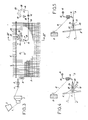
- FIGS 1 and 2 recall the principle of pneumatic insertion of the weft in an air jet weaving machine.
- the weft thread 1 comes from a supply spool 2, placed on one side of the weaving machine, and it first arrives at a pre-feeder 3, which measures lengths of thread corresponding exactly to a pick, and which delivers the weft thread 1 by successive lengths each corresponding to a pick. Then, after the passage of a brake 4 with positive control, the weft thread 1 arrives at a launch nozzle 5, supplied with compressed air, where it receives its initial acceleration in order to be inserted in the "crowd" of the threads chain 6.
- the weft thread 1 In crossing the crowd, the weft thread 1 is guided inside an insertion channel 7, delimited by the teeth of a confining comb or integrated into the main comb 8, as shown in FIG. 2
- the weft thread 1, traversing the insertion channel 7 over the entire width of the fabric 9 being formed, has its movement maintained by the auxiliary air pulses supplied by relay nozzles 10, supplied sequentially.
- the weft thread 1 can be kept stretched by a weft vacuum cleaner (not shown), until the comb 8 is struck.
- a chisel 11, placed on the side of the launching nozzle 5 makes it possible to separate the inserted pick from the rest of weft yarn 1, after which the next pick can be inserted in the same way.
- the extraction device object of the invention, performs two functions: - On the one hand, it "takes off” the defective pick 12 from the fabric 9 already formed, by moving this defective pick 12 from the previous pick 13 by a displacement substantially parallel to the warp threads 6; - on the other hand, it definitively extracts the defective pick 12, after “taking off” of the latter, in order to eliminate it from the tissue 9.
- the "take-off" of the defective pick 12 is ensured by pneumatic means and, more particularly, by a mobile air injector 14, which is connected by a flexible conduit 15 to a compressed air source 16, and which is horizontally movable in translation, as indicated by a double arrow 17, over the entire width of the fabric 9 and in a back and forth movement.
- the air injector 14 is disposed above the fabric 9, towards the junction of the two plies of warp threads 6, the air jet from this injector 14 being directed rearward between the two plies.
- the air injector 14 is mounted on a support rod 18, movable along a horizontal rectilinear guide 19 placed in a fixed position on the weaving machine, in a region located above the comb 8.
- Means for control are provided to ensure the translational drive of the support rod 18 along the guide 19.
- a roller 20 is also linked to the air injector 14 to precisely ensure positioning and guiding of the latter, the roller 20 moving on the fabric 9, preferably above the take-up roller 21.
- the air injector 14 remains stationary on one side of the weaving machine.
- the air injector 14 is supplied with compressed air by the source 16 and by the flexible duct 15, and it is moved either in one direction only to the other side of the machine, or in a back and forth movement bringing it back to its starting position.
- the air jet coming from the latter "takes off” the defective pick 12, by moving it in the direction of the warp threads 6 to move it away from the previous pick 13
- the defective pick 12 is positioned at a certain distance from the previous pick 13, not moved because retained between the warp threads 6.
- the injector d air 14 describes a return movement, it can be supplied under a given pressure during the "go" movement to take off the defective pick 12, and under a different and lower pressure during the "return” movement for position this pick 12.
- the air injector 14 intervenes so as to bring the defective pick 12 back into the insertion channel 7. It then becomes possible to permanently extract the pick defective 12 by the insertion channel 7, simply by supplying the relay nozzles 10, the pick 12 can finally be captured by a suction pipe 22 placed on the side of the machine, to be eliminated.
- FIGS. 3 and 4 also relate to an air jet weaving machine, with passage of the weft thread 1 in an insertion channel 7, and with an extraction device comprising an air injector 14 corresponding to the description given above.
- the final extraction of a defective pick 12 is ensured here by means of a movable member 23, capable of temporarily storing the defective pick 12.
- the movable member 23 is essentially presented as a hollow body 24, elongated and of curved shape especially at its ends which are facing forward. A first end 25 of the hollow body 24 is open, and its other end 26 is in the form of a grid.
- the movable member 23 also comprises a guide with roller 27, integral with the hollow body 24 and intended to move in an insertion channel 7.
- Drive means are provided for moving the movable member in translation 23, in synchronism with the air injector 4, in the space between the two plies of warp threads 6.
- the movable member 23 remains stationary, on one side of the weaving machine and outside of the fabric 9, as indicated in phantom in Figure 3.
- the air injector 14 is as previously supplied with compressed air by the source 16 and by the flexible conduit 15, and it is moved over the entire width of the fabric so as to "take off" the defective pick 12.
- the movable member 23 is moved so that the open end 25 of the hollow body 24 remains opposite the air injector 14.
- An air flow thus enters the hollow body 24 through the open end 25 , and it emerges from the other end 26 shaped as a grid.
- the "unstuck" wire, or the fragments of this wire are entrained by the air flow inside the hollow body 24, from which they cannot escape due to the presence of the grid.
- the defective pick 12 is recovered entirely inside the hollow body 24.
- the movable member 23 is brought back to one side of the machine, and stopped.
- the pick 12 stored by this movable member 23 can then be expelled from the hollow body 24, either by means of a special air blowing nozzle 28 located opposite the end 26 formed into a grid, or by bringing the air injector 14, to the after an overtravel, opposite this end 26.
- the final extraction of the defective pick 12, after its "takeoff" does not require any particular source of energy and no special connection, in particular pneumatic, since it uses the flow from the air injector 14.
- the "take-off" of the defective pick 12 is facilitated by the fact that the passage of the movable member 23 can slightly separate the two plies of warp threads 6.
- the movable member 23 for temporary storage of the defective frame 12 is guided along the insertion channel 7, it is understood that the use of such a movable member does not is not necessarily linked to the presence of an insertion channel.
- FIG. 5 partially showing a variant applied to a weaving machine with a comb 8 of the conventional type, without an insertion channel, the weft insertion system not being shown and may be arbitrary.
- the mobile recovery member 23 is here produced, and it operates in the same manner as described above; the only difference lies in the fact that the guide 27 rests on the comb 8 without following an insertion channel.
- the space between the two plies of warp threads 6 and the comb 8 can be greater here than in the previous case, which facilitates the making and the displacement of the movable member 23.
- FIGS. 6 and 7 also show an air jet weaving machine, with passage of the weft thread 1 in an insertion channel 7, and with an extraction device always comprising an air injector 14, conforms to the description given above.
- the final extraction of a defective pick 12 is provided here by independent suction means, distinct from both the relay nozzles 10 and the air injector 4.
- These means comprise a movable suction tube 29 , parallel to the direction of the weft threads, ending in a suction orifice 30 and connected to a source of compressed air 31.
- Control means not shown, introduce and move the suction tube 29 between the plies of warp threads 6, near the insertion channel 7.
- the air flow generated in the tube 29 ensures the suction of the defective pick 12 by the orifice 30 and its evacuation by the tube 29, after "takeoff" of this pick 12.
- suction means 29 to 31 which have just been described are also applicable without difficulty to weaving machines without insertion channel, in particular to weaving machines with weft insertion not pneumatic but mechanical, for example with lance machines.
- the control means used to move the air injector 14 and also, as the case may be, other elements such as the movable recovery member 23 or the movable suction tube 29, may include wires passing over pulleys, or flexible ribbons, or pebbles.
- this member In the case of a recuperator member 23, moved in synchronism with the air injector 14, it is possible to envisage for this member either an independent drive, or a drive by mechanical or magnetic coupling with the air injector 14.
- a mechanical clamp to hold the end of a pick after the insertion of the latter the action of the clamp must be neutralized before intervention of the defective weft thread extraction device.
- the neutralization of the clamp can be either controlled independently, or caused by the passage, for example at the right of this clamp, of a mobile element belonging to the extraction device, such as the air injector 14.
- the invention is not limited to the sole embodiments of this device for the extraction of a defective weft thread which have been described above, as examples; on the contrary, it embraces all of the variant embodiments and applications respecting the same principle.
- the means for driving and guiding the mobile elements such as the air injector 14 or the recuperator member 23, can be produced in any form.
- the device according to the invention remains applicable to weaving machines of all types.
Landscapes
- Engineering & Computer Science (AREA)
- Textile Engineering (AREA)
- Looms (AREA)
- Knitting Machines (AREA)
Applications Claiming Priority (2)
| Application Number | Priority Date | Filing Date | Title |
|---|---|---|---|
| FR8807257A FR2631980B1 (fr) | 1988-05-25 | 1988-05-25 | Dispositif pour l'extraction d'un fil de trame defectueux, sur une machine a tisser |
| FR8807257 | 1988-05-25 |
Publications (2)
| Publication Number | Publication Date |
|---|---|
| EP0344076A1 true EP0344076A1 (de) | 1989-11-29 |
| EP0344076B1 EP0344076B1 (de) | 1992-08-05 |
Family
ID=9366800
Family Applications (1)
| Application Number | Title | Priority Date | Filing Date |
|---|---|---|---|
| EP89420168A Expired - Lifetime EP0344076B1 (de) | 1988-05-25 | 1989-05-09 | Vorrichtung zum Entfernen eines Schussfehlers in einer Webmaschine |
Country Status (6)
| Country | Link |
|---|---|
| US (1) | US5005609A (de) |
| EP (1) | EP0344076B1 (de) |
| JP (1) | JPH02139457A (de) |
| DE (1) | DE68902359T2 (de) |
| ES (1) | ES2034723T3 (de) |
| FR (1) | FR2631980B1 (de) |
Cited By (3)
| Publication number | Priority date | Publication date | Assignee | Title |
|---|---|---|---|---|
| EP0446150A1 (de) * | 1990-03-06 | 1991-09-11 | Icbt Diederichs S.A. | Vorrichtung zum automatischen Entweben an Webmaschinen mit mechanischem Schusseintrag |
| EP0976859A1 (de) * | 1998-07-23 | 2000-02-02 | Lindauer Dornier Gesellschaft M.B.H | Verfahren zum Beheben eines Schussfehlers auf Webmaschinen, insbesondere Luftdüsenwebmaschinen mit pneumatischen Einlegern |
| WO2017194730A1 (de) * | 2016-05-12 | 2017-11-16 | Rwth Aachen | Vorrichtung und verfahren zur bildbasierten webfachüberwachung |
Families Citing this family (6)
| Publication number | Priority date | Publication date | Assignee | Title |
|---|---|---|---|---|
| JP2930739B2 (ja) * | 1990-12-28 | 1999-08-03 | 津田駒工業株式会社 | 不良糸除去方法 |
| SE507785C2 (sv) * | 1996-11-29 | 1998-07-13 | Texo Ab | Metod och anordning vid luft- eller gasströmsburen skyttel i vävmaskin |
| DE102006025265A1 (de) * | 2006-05-31 | 2007-12-06 | Lindauer Dornier Gmbh | Verfahren und Vorrichtung zum Bilden einer Gewebekante an einer Greiferwebmaschine |
| JP5769033B2 (ja) | 2012-11-30 | 2015-08-26 | 株式会社デンソー | 駆動装置 |
| JP6028773B2 (ja) * | 2014-09-09 | 2016-11-16 | 株式会社豊田自動織機 | エアジェット織機における緯糸処理方法 |
| JP7077968B2 (ja) * | 2019-01-14 | 2022-05-31 | 株式会社豊田自動織機 | エアジェット織機の緯糸処理装置 |
Citations (4)
| Publication number | Priority date | Publication date | Assignee | Title |
|---|---|---|---|---|
| FR2140679A1 (de) * | 1971-06-10 | 1973-01-19 | Te Strake Maschf | |
| EP0100939A2 (de) * | 1982-07-21 | 1984-02-22 | Kabushiki Kaisha Toyoda Jidoshokki Seisakusho | Verfahren und Vorrichtung zum Behandeln eines Schussfadens nach Stillsetzen eines schützenlosen Webstuhls |
| FR2537168A1 (fr) * | 1982-12-01 | 1984-06-08 | Rueti Te Strake Bv | Metier a tisser sans navette comprenant un moyen pour retirer, de la foule, des fils defectueux de trame |
| FR2583435A1 (fr) * | 1985-06-14 | 1986-12-19 | Picanol Nv | Procede et dispositif d'extraction de fils de trame defectueux d'un metier a tisser sans navette |
Family Cites Families (6)
| Publication number | Priority date | Publication date | Assignee | Title |
|---|---|---|---|---|
| US32916A (en) * | 1861-07-23 | Combined knife | ||
| USRE32916E (en) | 1969-10-22 | 1989-05-02 | Method for transporting a weft thread through a weaving shed and a loom for performing said method | |
| JPS58208441A (ja) * | 1982-05-26 | 1983-12-05 | 日産自動車株式会社 | 空気噴射式織機の緯入れ装置 |
| EP0228342B1 (de) * | 1985-12-20 | 1990-07-18 | GebràDer Sulzer Aktiengesellschaft | Luftstrahlwebmaschine |
| JPS6452850A (en) * | 1987-08-25 | 1989-02-28 | Toyoda Automatic Loom Works | Weft yarn treatment apparatus in jet loom |
| BE1000883A3 (nl) * | 1987-08-26 | 1989-05-02 | Picanol Nv | Werkwijze voor het verwijderen van een foutieve inslagdraad uit de gaap van een weefmachine en weefmachine die deze werkwijze toepast |
-
1988
- 1988-05-25 FR FR8807257A patent/FR2631980B1/fr not_active Expired - Fee Related
-
1989
- 1989-05-09 ES ES198989420168T patent/ES2034723T3/es not_active Expired - Lifetime
- 1989-05-09 DE DE8989420168T patent/DE68902359T2/de not_active Expired - Fee Related
- 1989-05-09 EP EP89420168A patent/EP0344076B1/de not_active Expired - Lifetime
- 1989-05-25 US US07/357,560 patent/US5005609A/en not_active Expired - Fee Related
- 1989-05-25 JP JP1130283A patent/JPH02139457A/ja active Pending
Patent Citations (4)
| Publication number | Priority date | Publication date | Assignee | Title |
|---|---|---|---|---|
| FR2140679A1 (de) * | 1971-06-10 | 1973-01-19 | Te Strake Maschf | |
| EP0100939A2 (de) * | 1982-07-21 | 1984-02-22 | Kabushiki Kaisha Toyoda Jidoshokki Seisakusho | Verfahren und Vorrichtung zum Behandeln eines Schussfadens nach Stillsetzen eines schützenlosen Webstuhls |
| FR2537168A1 (fr) * | 1982-12-01 | 1984-06-08 | Rueti Te Strake Bv | Metier a tisser sans navette comprenant un moyen pour retirer, de la foule, des fils defectueux de trame |
| FR2583435A1 (fr) * | 1985-06-14 | 1986-12-19 | Picanol Nv | Procede et dispositif d'extraction de fils de trame defectueux d'un metier a tisser sans navette |
Cited By (4)
| Publication number | Priority date | Publication date | Assignee | Title |
|---|---|---|---|---|
| EP0446150A1 (de) * | 1990-03-06 | 1991-09-11 | Icbt Diederichs S.A. | Vorrichtung zum automatischen Entweben an Webmaschinen mit mechanischem Schusseintrag |
| FR2659361A1 (fr) * | 1990-03-06 | 1991-09-13 | Saurer Diederichs Sa | Dispositif de detissage automatique pour machines a tisser avec organes d'insertion mecanique de la trame. |
| EP0976859A1 (de) * | 1998-07-23 | 2000-02-02 | Lindauer Dornier Gesellschaft M.B.H | Verfahren zum Beheben eines Schussfehlers auf Webmaschinen, insbesondere Luftdüsenwebmaschinen mit pneumatischen Einlegern |
| WO2017194730A1 (de) * | 2016-05-12 | 2017-11-16 | Rwth Aachen | Vorrichtung und verfahren zur bildbasierten webfachüberwachung |
Also Published As
| Publication number | Publication date |
|---|---|
| DE68902359D1 (de) | 1992-09-10 |
| DE68902359T2 (de) | 1993-03-11 |
| FR2631980A1 (fr) | 1989-12-01 |
| ES2034723T3 (es) | 1993-04-01 |
| US5005609A (en) | 1991-04-09 |
| JPH02139457A (ja) | 1990-05-29 |
| EP0344076B1 (de) | 1992-08-05 |
| FR2631980B1 (fr) | 1990-08-24 |
Similar Documents
| Publication | Publication Date | Title |
|---|---|---|
| FR2527655A1 (fr) | Metier a tisser sans navette comprenant un moyen pour retirer des fils defectueux de trame, de la foule | |
| EP1923495B1 (de) | Verfahren zur Verarbeitung eines Schussfadenseintragsfehlers in einer Webmachine | |
| EP0344076B1 (de) | Vorrichtung zum Entfernen eines Schussfehlers in einer Webmaschine | |
| CH643613A5 (fr) | Dispositif a buse mobile pour insertion pneumatique de la trame sur une machine a tisser sans navette. | |
| FR2537168A1 (fr) | Metier a tisser sans navette comprenant un moyen pour retirer, de la foule, des fils defectueux de trame | |
| FR2505370A1 (fr) | Procede et dispositif pour interrompre et commencer le filage dans un poste de filature a fibres liberees | |
| EP0229084B1 (de) | Verfahren und vorrichtung zum entfernen von fehlerhaften schussfäden in webmaschinen | |
| EP0446150B1 (de) | Vorrichtung zum automatischen Entweben an Webmaschinen mit mechanischem Schusseintrag | |
| FR2584745A1 (fr) | Procede d'insertion des fils de trame dans des metiers a tisser sans navettes, par l'intermediaire de pinces engagees et retractees de la foule et equipees de dispositifs de pincement des fils de trame, et metier a tisser sans navettes pour la mise en oeuvre dudit procede | |
| EP0342135A1 (de) | Schussfadensaug und -haltevorrichtung für Webmaschinen mit pneumatischem Schusseintrag | |
| BE1023294B1 (fr) | Procede pour retirer un fil de trame qui a ete incorrectement entrecroise dans un metier a tisser du type a jet d'air | |
| FR2526053A1 (fr) | Dispositif de reception et de controle de la trame, pour machine a tisser sans navette a insertion de trame pneumatique | |
| FR2506795A1 (fr) | Procede et dispositif pour l'insertion de duites selon une sequence donnee sur une machine a tisser | |
| EP0389387A1 (de) | Schussfadenliefervorrichtung für eine Webmaschine mit Strahleintrag | |
| EP0266286A2 (de) | Vorrichtung zum Schusseintrag bei schützenlosen Webmaschinen | |
| FR2642769A1 (fr) | Dispositif pour la detection de defauts du fil de trame dans une machine a tisser | |
| CH654349A5 (fr) | Dispositif pour la preparation et l'insertion d'un fil de trame dans la foule d'un metier a tisser. | |
| FR2477587A1 (fr) | Dispositif pour l'insertion d'un fil de trame dans la foule d'un metier a tisser | |
| EP0406128A1 (de) | Schussfadenliefervorrichtung für pneumatische Webmaschinen | |
| FR2618804A1 (fr) | Procede et dispositif d'extraction automatique de trames defectueuses sur machine a tisser sans navette | |
| JP2530132B2 (ja) | 無杼織機の不良糸除去装置 | |
| CH617729A5 (de) | ||
| FR2634500A1 (fr) | Dispositif d'aspiration et de retenue du fil de trame, pour machine a tisser avec insertion de trame pneumatique | |
| BE558822A (de) | ||
| BE634547A (de) |
Legal Events
| Date | Code | Title | Description |
|---|---|---|---|
| PUAI | Public reference made under article 153(3) epc to a published international application that has entered the european phase |
Free format text: ORIGINAL CODE: 0009012 |
|
| AK | Designated contracting states |
Kind code of ref document: A1 Designated state(s): BE CH DE ES GB IT LI |
|
| 17P | Request for examination filed |
Effective date: 19900129 |
|
| 17Q | First examination report despatched |
Effective date: 19910624 |
|
| GRAA | (expected) grant |
Free format text: ORIGINAL CODE: 0009210 |
|
| ITF | It: translation for a ep patent filed | ||
| AK | Designated contracting states |
Kind code of ref document: B1 Designated state(s): BE CH DE ES GB IT LI |
|
| REF | Corresponds to: |
Ref document number: 68902359 Country of ref document: DE Date of ref document: 19920910 |
|
| GBT | Gb: translation of ep patent filed (gb section 77(6)(a)/1977) | ||
| REG | Reference to a national code |
Ref country code: ES Ref legal event code: FG2A Ref document number: 2034723 Country of ref document: ES Kind code of ref document: T3 |
|
| PLBE | No opposition filed within time limit |
Free format text: ORIGINAL CODE: 0009261 |
|
| STAA | Information on the status of an ep patent application or granted ep patent |
Free format text: STATUS: NO OPPOSITION FILED WITHIN TIME LIMIT |
|
| 26N | No opposition filed | ||
| PGFP | Annual fee paid to national office [announced via postgrant information from national office to epo] |
Ref country code: CH Payment date: 19930728 Year of fee payment: 5 |
|
| PGFP | Annual fee paid to national office [announced via postgrant information from national office to epo] |
Ref country code: GB Payment date: 19930927 Year of fee payment: 5 |
|
| PGFP | Annual fee paid to national office [announced via postgrant information from national office to epo] |
Ref country code: ES Payment date: 19930930 Year of fee payment: 5 Ref country code: DE Payment date: 19930930 Year of fee payment: 5 |
|
| PGFP | Annual fee paid to national office [announced via postgrant information from national office to epo] |
Ref country code: BE Payment date: 19931013 Year of fee payment: 5 |
|
| PG25 | Lapsed in a contracting state [announced via postgrant information from national office to epo] |
Ref country code: GB Effective date: 19940509 |
|
| PG25 | Lapsed in a contracting state [announced via postgrant information from national office to epo] |
Ref country code: ES Free format text: LAPSE BECAUSE OF NON-PAYMENT OF DUE FEES Effective date: 19940510 |
|
| PG25 | Lapsed in a contracting state [announced via postgrant information from national office to epo] |
Ref country code: LI Effective date: 19940531 Ref country code: CH Effective date: 19940531 Ref country code: BE Effective date: 19940531 |
|
| BERE | Be: lapsed |
Owner name: S.A. SAURER DIEDERICHS Effective date: 19940531 |
|
| GBPC | Gb: european patent ceased through non-payment of renewal fee |
Effective date: 19940509 |
|
| REG | Reference to a national code |
Ref country code: CH Ref legal event code: PL |
|
| PG25 | Lapsed in a contracting state [announced via postgrant information from national office to epo] |
Ref country code: DE Effective date: 19950201 |
|
| REG | Reference to a national code |
Ref country code: ES Ref legal event code: FD2A Effective date: 19990503 |
|
| PG25 | Lapsed in a contracting state [announced via postgrant information from national office to epo] |
Ref country code: IT Free format text: LAPSE BECAUSE OF NON-PAYMENT OF DUE FEES;WARNING: LAPSES OF ITALIAN PATENTS WITH EFFECTIVE DATE BEFORE 2007 MAY HAVE OCCURRED AT ANY TIME BEFORE 2007. THE CORRECT EFFECTIVE DATE MAY BE DIFFERENT FROM THE ONE RECORDED. Effective date: 20050509 |