EP0342973B1 - Positionskontrollsystem für eine Speicherplatteneinheit - Google Patents
Positionskontrollsystem für eine Speicherplatteneinheit Download PDFInfo
- Publication number
- EP0342973B1 EP0342973B1 EP89305024A EP89305024A EP0342973B1 EP 0342973 B1 EP0342973 B1 EP 0342973B1 EP 89305024 A EP89305024 A EP 89305024A EP 89305024 A EP89305024 A EP 89305024A EP 0342973 B1 EP0342973 B1 EP 0342973B1
- Authority
- EP
- European Patent Office
- Prior art keywords
- signal
- track
- disk
- output
- control system
- Prior art date
- Legal status (The legal status is an assumption and is not a legal conclusion. Google has not performed a legal analysis and makes no representation as to the accuracy of the status listed.)
- Expired - Lifetime
Links
Images


Classifications
-
- G—PHYSICS
- G11—INFORMATION STORAGE
- G11B—INFORMATION STORAGE BASED ON RELATIVE MOVEMENT BETWEEN RECORD CARRIER AND TRANSDUCER
- G11B21/00—Head arrangements not specific to the method of recording or reproducing
- G11B21/02—Driving or moving of heads
- G11B21/10—Track finding or aligning by moving the head ; Provisions for maintaining alignment of the head relative to the track during transducing operation, i.e. track following
- G11B21/106—Track finding or aligning by moving the head ; Provisions for maintaining alignment of the head relative to the track during transducing operation, i.e. track following on disks
Definitions
- the present invention relates to a position control system for allowing a data transducer to trace a data track in a disk storage device, and more particularly to a position control system for a disk storage drive system in which a data transducer can be moved to a selected data recording track at a high speed and controlled to keep its relative position to the data recording track.
- the data transducer position control system is desired to be more compact in size and more accurate in operation.
- the position control system acts as a positioning drive device for allowing the record or playhack transducer to trace a reference data track in a magnetic disk storage device or an optical disk storage device.
- the compactness is required for the purpose of increasing the recording capacity in a given size and the high accuracy is also needed for increasing the track density for mass storage.
- the amplitude of track deflection will be about several tens to some dozen tens of micrometers , considerably greater than the width (about 1.6 ⁇ m) of a track to be traced, due to the eccentricity of the center of rotation after replacement of a disk medium and/or the deflection of a rotary shaft of spindle motor for rotation of the disk.
- FDD floppy disk drive
- another kind of track deflection will result from the expansion or shrinkage of a base film of the disk medium caused by heatup in addition to the same track deflection as of an optical disk storage device.
- the amplitude of track deflection is rather smaller than that of the optical disk storage device, and the deflection is some dozen to several tens of micrometers in operation.
- the track deflection will not be negligible when the track is reduced in width for mass storage at a high track density.
- a method in which the deflection of a track is estimated by twice differentiating a signal which is the sum of a tracking error signal and an integration signal obtained by twice integrating an input signal to the driver unit for actuating a data transducer for tracking movement.
- the estimation signal corresponding to one rotation of the disk is stored in a memory, and is then read out during a tracking mode and added to the input signal to the driver unit.
- the traceability of the data transducer can be improved, for example, as disclosed by US Patent 4, 594, 622.
- a prior art data transducer position control system for disk storage drive system has problems in that the control of variations and noise generated during the estimation of track deflection is too difficult to be executed in practice or as the arithmetic operation of a repeatable error compensation is troublesome.
- EP-A-0113815 describes a servo system for a magnetic disk storage drive system in which positional information is provided in the data tracks in addition to the data (sector servo).
- a voice coil motor is used as the disk file actuator.
- a model of the voice coil motor is used to generate a simulated position error signal based on the value of current being supplied to the voice coil motor. This simulated error signal is compared with a position error signal derived from the recorded positional information and used to generate a continuous error signal even if the positional data is intermittent.
- EP-A-0130248 describes a track-following servo system for a disk storage system.
- a prediction of track eccentricity is fed forward into the normal feedback control loop driving the head position actuator.
- the eccentricity-related function is derived by combining functions of a position error signal and of an input signal to the head position actuator.
- the present invention provides a position control system for a disk storage drive system including a data transducer for record and playback of information stored in a given data track of an information storage disk having a plurality of data storage tracks thereon, comprising: an actuator means for actuating the data transducer to move the data transducer; a drive means for driving the actuator means in accordance with a reference position command signal and the current position signal; a tracking error detector means for detecting a positional difference of the data transducer from a desired data track and producing a tracking error signal; a track deflection estimator means for estimating a deflection of a track resulting from either eccentricity or undulation of the data track and generating a feed-forward signal on the estimation; and a discrete-time control loop means for controlling the drive means in accordance with the tracking error signal, including a compensating position calculator means for calculating a compensating position command signal from the tracking error signal and an interpolation calculator means for generating an interpolation signal which is applied to the drive means through inter
- the eccentricity or undulation of a data track is estimated by the track deflection estimator and with its resultant information data, the feed-forward control is then executed, whereby the traceability can be improved in accuracy and stability.
- the feed-forward signal applied to the driver unit is advanced in phase so as to improve the traceability.
- the current position of the driver unit is identified with high accuracy and resolution by the position encoder so that the minimal positioning is possible and the impact from vibration is lessened through increasing the stiffness. As a result, the high density of data tracks can be obtained.
- the interpolation signal is generated by the interpolation- calculator through interpolating process of a feed-forward signal and an output from the compensating position calculator and then, added to the reference position command signal whereby the traceability can be improved.
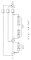
- Fig. 1 is a block diagram of a position control system for a disk storage drive system according to the present invention.
- the element 12 is a driver unit for actuating a data transducer 2 to move about on the disk.
- the driver unit 12 includes an actuator 1 for movement of the data transducer 2, a position encoder 3 connected mechanically with the moving part of the actuator 1 for producing a current position signal ya upon detecting the position of the actuator 1 constantly, a compensator 5, a power supply circuit 4 for energizing the actuator 1 in accordance with an output from the compensator 5, a sample and hold circuit 15 for the continuous conversion of discrete-time signals ya derived from the position encoder 3, and a comparator 6 for calculating a difference e2 between the reference position command signal rs and the output of the sample and hold circuit 15.
- the compensator 15 calculates a control measure of the actuator 1 with reference to the difference e2.
- a servo-loop extending from the output of the position encoder 3 via the comparator 6, the compensator 5, and the power supply circuit 4 to the actuator 1, constitutes a position control loop.
- the position encoder 3 is adapted to detect the action of a moving part constantly and its current position output signal is a linear representation of the displacement of the data transducer 2 from a specific reference position within the movable range.
- the compensator 5 is also arranged for following the reference position command signal rs quickly with little error. This servo-loop is substantially an absolute positioning system and thus, will fail to provide the precise tracking along a data track which may deflect as the disk rotates.
- r Represented by r is a measure of eccentricity or undulation of a selected data track 13 on the disk 14 situated just beneath the data transducer 2, also referred to as a deflection of the track ,while ys is an absolute position of the data transducer 2.
- a tracking error detector 7 detects a relative position error el between the data track 13 and the data transducer 2.
- a compensating position calculator 8 produces a compensating position command signal rd through control calculation with the tracking error e1.
- a track deflection estimator 9 estimates the amplitude of the track deflection upon receiving both the tracking error signal el and the current position signal ya and produces a feed-forward signal rc.
- the compensating position command signal rd and the feed-forward signal rc are then supplied as an interpolation calculator 10 where a specific interpolation process is executed.
- the output from the interpolation calculator 10 is a reference position command signal rs.
- the embodiment shown in Fig. 1 employs a tracking servo-system also termed a sector servo-system or a sampling servo-system.
- the system is arranged such that on the basis of each particular piece of servo information which is essential for tracking and which is embedded in the border area between fan-shaped sectors formed on the disk, a relative position signal (a tracking error signal) of the data transducer 2 with respect to the target data track is detected in a discrete-time base and then supplied as feedback for positioning in a closed loop arrangement.
- the system is mainly constituted by a discrete-time control loop for allowing the data transducer 2 to trace the data track 13 with the tracking error signal e1 kept at a minimum.
- the discrete-time control loop represents a servo-loop from the data transducer 2 via the tracking error detector 7, the compensating position calculator 8, and the interpolation calculator 10 to the driver unit 12. While a deviation of the data transducer 2 from the selected data track 13 varies in time, the position of the data track 13 is identified only intermittently in the sector servo-system and thus, the tracking error signal e1 will be outputted as a discrete-time signal from the tracking error detector 7. The tracking error signal e1 is then processed by a specific control calculation in the compensating position calculator 8 to generate the compensating position command signal rd.
- the compensating position calculator 8 has a time discrete processing system containing a deviation compensating factor or, if needed, a stability compensating factor and acts primarily for the control of the offset.
- the tracking error detector 7 is arranged to detect the relative tracking error signal e1 of the data transducer 2 with respect to the data track 13.
- the position encoder 3 detects the position of the actuator 1 and produces a current position signal ya.
- the absolute position ys of the data transducer 2 is indirectly represented by the current position signal ya, which is expressed as: ys ⁇ ya Therefore, from the statements (1) and (2), the values r is determined by: r ⁇ e1 + ya
- the approximate equation (3) means that the track deflectiuon of a data track can be estimated from the tracking error signal e1 and the current position signal ya.
- the track deflection estimator 9 includes an adder for summing the tracking error signal e1 and the current position signal ya and calculates an estimate of the track deflection from the equation (3).
- the resultant estimation rc of a track deflection r is then designated as a feed-forward signal.
- the feed-forward control is a procedure of applying an external signal to the servo-loop, in which the controllability thereof can be increased without reducing the stability when an external signal has been supplied thereto.
- the estimation rc of the track deflection r in the position control system of the present invention is an external signal outside the servo-loop or the discrete-time control loop. More particularly, the input of this signal to the interpolation calculator 10 stands for an application to the servo-loop. Accordingly, the stability in the servo-loop remains no doubt unchanged in the event.
- the driver unit 12 cannot respond instantly in practice when the reference position command signal rs is inputted and thus, a time delay will occur. More specifically, the transfer properties of the driver unit 12 include a phase delay within the basic and harmonic frequency band of a disk revolution frequency contained primarily in the track deflection r of a data track. Also, another phase delay occurs which is derived from the sample and hold procedure of the discrete-time control loop. As a result, the data transducer 2 fails to trace a desired data track with the accuracy of more than a specific degree.
- the track deflection estimator 9 in the position control system for disk storage drive system of the present invention is thus arranged as described below.
- Fig. 2 is a block diagram of the track deflection estimator 9 according to an embodiment of the present invention.
- the track deflection estimator 9 comprises a memory section 21, digital compensators K1, K2, ... Kn-1, and Kn, and an adder 22.
- Z ⁇ 1 is a unit memory for holding an estimation signal of track deflection ra for a time T equal to a sampling period in the discrete-time control loop.
- the memory section 21 is thus constituted for holding the track deflection estimation signals ra corresponding to one rotation of disk by connecting in series n (n is a positive integer) unit memories wherein n corresponds to the number of sectors.
- the output from the final stage of the memory section 21 is connected to the input of the same so that the track deflection estimation signals ra held therein can pass each unit memory recursively as synchronized with the rotation of the disk.
- the memory section 21 may also be formed of shift registers or the like.
- Each of the digital compensators K1, K2, ... Kn-1, and Kn comprises adders and/or multipliers for amplifying or digital filtering the output signal of a unit memory of the memory section 21.
- the adder 22 is arranged to sum up the outputs of the digital compensators for producing the feed-forward signal rc.
- the track deflection estimator 9 of Fig. 2 The operation of the track deflection estimator 9 of Fig. 2 is described below As shown in Fig. 2, the track deflection estimation signals ra corresponding to one rotation of the disk are stored in the n unit memories and during tracking, retrieved from their respective unit memories. The estimation signals are then supplied to their respective digital compensators and summed up by the adder 22 to produce a track deflection estimation signal rc which is equal to or a bit advanced in phase relative to the actual track deflection r. Then, the track deflection estimation signal rc is supplied to the interpolation calculator 10 together with the output signal rd of the compensating position calculator 8 shown in Fig. 1. When the output from the interpolation calculator 10 is inputted to the driver unit 12, the actuator 1 moves to eliminate a delay in the tracking motion of the data transducer 2.
- the track deflection estimator 9 may be formed of such hardware as described above or a microprocessor containing software for execution of a similar procedure.
- Figs.3(a)-3(c) are waveform diagrams showing the track deflection estimation signal ra of the track deflection estimator of Fig. 2 and respective output signals of the digital compensator Ki and the adder 22.
- the digital compensator Ki is a multiplier for multiplying the signal by 0.1.
- the letter i represents the number of a unit memory as numbered from the front to i-th and is designated as i ⁇ n ⁇ 3/4. While the digital compensators K1 to Kn-1 except Ki are removed, the Kn is an amplifier of gain 1.
- Fig. 3(a) shows the track deflection estimation signal ra
- Fig. 3(b) shows a signal given by multiplying output signal rc given by summing the former signals in the adder 22. If the track deflection contains only a basic frequency, the signal waveforms of Fig. 3 are respectively described as,
- a multiplier 42 multiplies the track deflection estimation signal ra by ⁇ ( ⁇ is a real number and ⁇ ⁇ 1).
- Another multiplier 43 multiplies the output signal rb from the final stage of the memory section 21 by (1 - ⁇ ) .
- An adder for 44 adds the outputs of the multipliers 42 and 43.
- the initial setting of a track deflection estimation signal is inputted to the memory section 21 in synchronism with a rotation of the disk while a is designated as 1 at the first rotation of the disk. If ⁇ is 0.5 at the second rotation of the disk, the track deflection estimation signal ra is multiplied by 0.5 in the multiplier 42 and also, the track deflection estimation signal rb from the memory section 21 is multiplied by 0.5 in the multiplier 43. Then, the outputs from the multipliers 42 and 43 are summed up by the adder 44 and stored again in the memory section 21.
- the coefficient in the multiplier 43 is 1 - ⁇ while the same in the multiplier 42 is ⁇ , so that the signals stored in the memory section 21 can be constantly normalized in amplitude.
- This track deflection estimating procedure features in which the track deflection estimation signal ra stored in the memory section 21 at a particular moment of time, will decrease at a specific rate of 0.25 times the original amount in the second rotation and 0.125 times in the third rotation as the time passes. Accordingly, the remaining percentage of estimation signals which were stored in the past rotation in the memory section 21 will increase as the value of ⁇ becomes close to zero.
- a primary object of the estimation procedure according to the present invention is to smooth amplitude variations of the track deflection estimation signal and level random noise factors contained therein through repeating the above mentioned operation.
- the track deflection estimator may be formed of hardware as described above or by a microprocessor having software for execution of a similar procedure.
- the estimation is effected with the data transducer 2 kept movable for tracing a given track. More specifically, the track deflection estimation procedure of Fig. 4 is carried out with the discrete-time control loop 11 kept activated in the arrangement of Fig. 1.
- the estimation is carried out with the discrete-time control loop 11 kept unactivated in the arrangement of Fig. 1 while the absolute position of the data transducer 2 remains unchanged by applying a specified instruction to the drive unit 12.
- the tracking error detector 7 produces a corresponding signal to the track deflection and the output of the position encoder 3 is a direct current.
- the estimation is carried out with the data transducer 2 either kept movable for tracing an unspecified track or kept fixed adjacent to the track.
- the track deflection estimation is carried out intermediate the track seek operations. More specifically, the estimation procedure is carried out for a period of time with the data transducer 2 kept movable for tracing an unspecified track or fixed adjacent to the track and after shifting to another track, the same procedure will be repeated again.
- the spindle motor will stop when the access to a disk stops for a certain period of time and the track deflection estimation should thus be carried out intermittently between access operations.
- the track deflection estimation requires at least a duration corresponding to one rotation of the disk and more particularly, a smoothing period taken for improved estimation with less noise while the disk is rotated 2 or 3 more times along a desired track.
- the track deflection estimation is preferably carried out just after the spindle motor starts rotating with the disk loaded in the floppy disk drive system and before the spindle motor stops. If the track deflection is varied during a considerable length of time when the spindle remains stopped, the estimation can be carried out when it is detected that the period between stop and restart of the spindle exceeds a predetermined time.
- Fig. 5 is a block diagram showing the position control system for disk storage drive system of the present invention in the track seek mode.
- the driver unit 12 acts as a main operator in the track seek mode.
- a track seek instruction rk and an output rc from the track deflection estimator 9 are applied to an adder 51 which in turn sends its output to the driver unit 12.
- the memory section 21 (not shown) in the track deflection estimator 9 is formed in the same recursive arrangement as of Fig. 2 and its final stage output is supplied outwardly through no digital compensator.
- the driver unit 12 is actuated according to the output signal of the adder 51.
- the track seek instruction rk as a position signal is entered without any output of the track deflection estimator 9 applied to the adder 51, the data transducer 2 moves from a track to another track in response to the instruction.
- the output rc of the track deflection estimator 9 is supplied to the adder 51 together with the track seek instruction rk so as to correct the deflection of the target track caused after the track seeking.
- Fig. 1 employs a sector servo-system for which a trade-off of design is established with respect to the number of sectors.
- the number of sectors is great, the sampling frequency in discrete-time control system increases and will be available in a wide band for the control. On the contrary, a servo-area portion of the recording surface of the disk increases in size and the capacity of storage will be reduced when the formatting on the disk is completed. Hence, the number of the sectors should be kept to a minimum to increase the availability on the disk recording surface.
- the sampling frequency in a control system decreases and will be available only in a narrow band. This allows the traceability to be increased with much difficulty.
- the controllable range is commonly adjusted so as to equal several to ten times the basic frequency of the track deflection, a control gain on the discrete-time compensator can be increased for the control of the track deflection.
- the control gain will hardly increase.
- the number of the sectors is small, the length of a sampling interval will increase while a certain command signal only is applied to the actuator for drive of the data transducer. As the track changes position continuously due to track deflection, an off-track will result from a considerable degree of track deflection even if the control gain is increased.
- Fig. 6 is a block diagram of the interpolation calculator 10 in an embodiment of the present invention, in which element 61 is an adder for combining the compensating position command signal rd with the feed-foward signal rc; element 62 is an interpolator for performing numerical interpolation upon receiving an output w from the adder 61; and element 63 is a sample and hold circuit for converting a discrete-time signal v of the interpolator 62 into a continuous signal.
- the hold time Th of the sample and hold circuit 63 is expressed as: Th ⁇ T
- the interpolation is an arithmetic operation in which if values of a function f(x) at m points x1, x2, ... and xm are known, a value of f(x) at a point x is obtained from the known values of f(x). More precisely, an interpolation is when the value of x is between the minimum and maximum of the values of m points, but is otherwise referred to as extrapolation. Lagrange's interpolation is one of the known similar procedures.
- interpolation The function and operation of the interpolator 62 will specifically be described with reference to a simple example in which m is 2, that is to say, interpolation or extrapolation is made with the use of a couple of factors.
- interpolation the relative procedure is not distinguished between interpolation and extrapolation and will be referred to as "interpolation" hereinafter.
- Figs.7(a)-7(e) are waveform diagrams of signals showing the track deflection r with no interpolation procedure carried out, the output w from the adder 61, the reference position command signal rs, the absolute position ys of the data transducer, and the real tracking error es incorporated in the position control system for disk storage drive system of the present invention shown in Figs. 1 and 6.
- Fig. 7(b) shows a discrete-time signal designated on the abscissa axis kT (k is a positive integer) at sampling intervals of T.
- the reference position command signal rs which is obtained by sampling and holding the output w of the adder 61, is expressed in a wide step waveform.
- the data transducer position ys or a response of the driver unit 12 to the signal rs is also shown in a wide step waveform. Accordingly, the real tracking error es has an oscillatory waveform of great amplitude.
- Fig. 8 is a block diagram showing an interpolator for executing a first interpolation procedure, in which element 81 is a sampler for sampling at intervals of period T/m the input signal w which has been sampled at T period intervals and element 82 is a digital filter H(z) provided in the form of an integral filter for smoothing an input signal. Both the sampler 81 and the digital filter 82 are actuated according to an interpolation pulse having a period T/m.
- Elements 83 and 84 are multipliers for multiplying the signal by a (a is a positive real number and a ⁇ 1) and by 1 - a respectively.
- Element Z ⁇ 1 is a register for holding data for the sampling period T/m.
- the interpolator may be formed of hardware as described above or by a microprocessor having software for executing a similar procedure.
- a sample signal denoted by the black dot is the input w (kT) uninterpolated.
- An interpolated signal is represented by the white dot.
- the sample signal w (k ⁇ T/m) is then supplied to the digital filter 82 which is actuated in accordance with the T/m period interpolation pulse.
- the signal v smoothed by the digital filter 82 is held by the sample and hold circuit 63 of Fig.6 for output of a signal rs which has a small step waveform as compared with the signal rs of Fig. 7(c).
- the real tracking error es will be small in amplitude and moderate in its waveform. Additionally, by increasing the interpolation points m, the output es will be smooth in the response and further smaller in amplitude.
- the output w from the discrete-time compensator is sampled to a considerable degree and passed through a digital integral filter, whereby the track traceability can be improved.
- Fig. 10 is a block diagram showing another arrangement of an interpolator for execution of a second interpolation procedure, in which element 101 is a register actuated in synchronism with a sector detection pulse for holding the input signal w for a period of T.
- Element 102 is an adder for calculating a difference between the current input w(kT) and the register output w((k-1)T).
- the interpolator may be formed of hardware as described above or by a microprocessor having software for executing a similar procedure.
- Figs.11(a)-11(e) are waveform diagrams of signals interpolated by the second interpolation procedure.
- a sample signal denoted by the black dot is the input w(kT) uninterpolated.
- An interpolation is carried out in which the signal values (represented by the white dots) are obtained by dividing the extension (represented by the broken line) which extends across the summit of the current sample signal w(kT) through the summit of the preceding sample signal w((k-1)T), by the number m in the following sample period.
- the interpolated output v (represented by both the black dots and the white dots) is held by the sample and hold circuit 63 of Fig. 6 for output of a signal rs, as shown in Fig.11(c) where the hatching area represents the result of interpolation.
- the signal rs has a small step waveform as compared with that of Fig. 7(c) and thus, the response ys of the driver unit 12 becomes moderate in the waveform as compared with that of Fig. 7(d). Consequently, the real tracking error es will be small in amplitude and moderate in its waveform.
- the output es will be smooth in its response and further smaller in amplitude. The track traceability can thus be improved by interpolation of the signal w.
- Fig. 12 is a block diagram showing an interpolator for execution of a third interpolation procedure, in which element 121 is a memory section actuated in synchronism with a sector detection pulse for holding a signal w corresponding to one rotation of the disk.
- Element 122 is an adder for calculating a difference between the output x(kT) and the output x((k+1)T).
- the interpolator may be formed of hardware as described above or by a microprocessor having software for executing a similar procedure.
- Figs.13(a)-13(b) are waveform diagrams of signals interpolated by the third interpolation procedure. Shown in Fig. 13(a) is a discrete-time signal put into the memory section 121 through learning or in reference to a repeatable period. As shown in Fig.13(b), a sample signal denoted by the black dot is the time-discrete signal w(kT) supplied to the interpolator in real time.
- the interpolation according to the sample signal stored in the memory section 121 is carried out in which a sloping portion (represented by the broken line) between the current sampling time and the following sampling time is obtained from the sample signal stored in the memory section 121 and is used for interpolation of the following sample period (represented by the white dot). This procedure is made on each sample input for interpolation in correspondence to one rotation of the disk.
- the interpolated signal v is then held by the sample and hold circuit 63 of Fig.6 for output of a signal rs.
- the signal rs is supplied to the driver unit 12 and thus, the track traceability can thus be improved as well as in the first or second interpolation procedure.
- Fig. 14(a) is a block diagram of a compensating position calculator 8 in an embodiment of the present invention, in which element Z ⁇ 1 is a unit memory for holding a discrete-time signal of sample time T, element Ha(z) is a low-band compensation digital filter, element Hb(z) is a recursive digital filter, and element LPF is a low-pass filter contained within the recursive digital filter for stabilization.
- Multipliers L1, L2,...and L4 are also provided for multiplying the input signal by a coefficient.
- Fig. 14(b) shows the frequency characteristics of a transfer function from the tracking error el to the compensating position command signal rd. While f0 is a rotation frequency of the disk, a high gain is apparently given in the harmonic frequency component which is a multiplication of the basic frequency f0 by an integer.
- the arrangement of the compensating position calculator is not limited to the above mentioned system and may be formed of a low-band compensator capable of substantially increasing the gain of a low frequency component included in the tracking error signal.
Landscapes
- Moving Of The Head To Find And Align With The Track (AREA)
Claims (14)
- Positionssteuersystem für ein Plattenspeichersystem (11) mit einem Datenwandler (2) zur Aufnahme und Wiedergabe von Information, die in einer gegebenen Datenspur einer Informations-Speicherplatte (14), die eine Vielzahl von Datenspeicherspuren besitzt, gespeichert ist, umfassend:
eine Betätigungseinrichtung (1) zur Betätigung des Datenwandlers, um den Datenwandler zu bewegen;
eine Antriebseinrichtung (12) zum Antreiben der Betätigungseinrichtung nach Maßgabe eines Referenzposition-Befehlssignals und des aktuellen Positionssignals;
eine Nachführfehler-Ermittlungseinrichtung (7) zur Ermittlung einer Positionsdifferenz des Datenwandlers von einer gewünschten Datenspur und Erzeugung eines Nachführfehlersignals;
eine Spurabweichung-Schätzungseinrichtung (9) zum Schätzen einer Abweichung einer Spur, die aus entweder Exzentrizität oder Welligkeit der Datenspur resultiert, und Erzeugen eines Optimierungssignals auf der Schätzung, und
eine zeitdiskrete Regelschleifeneinrichtung (2, 7, 8, 10) zum Steuern der Antriebseinrichtung nach Maßgabe des Nachführfehlersignals, einschließlich einer Ausgleichsposition-Berechnungseinrichtung (8) zum Berechnen eines Ausgleichsposition-Befehlssignals aus dem Nachführfehlersignal und einer Interpolations-Berechnungseinrichtung (10) zum Erzeugen eines Interpolationssignals, das an die Antriebseinrichtung durch Interpolation mit dem Optimierungssignal und dem Ausgleichsposition-Befehlssignal angelegt wird,
gekennzeichnet durch eine Positions-Codierungseinrichtung (3) zum Ermitteln einer Veränderung in der Bewegung des Datenwandlers und zum Erzeugen eines aktuellen Positionssignals, das eine aktuelle Position des Datenwandlers darstellt, und dadurch, daß die Spurabweichung-Schätzungseinrichtung (9) umfaßt:
eine erste Additionseinrichtung (41), die das Nachführfehlersignal und das aktuelle Positionssignal der Positions-Codierungseinrichtung aufsummiert; eine Speichereinrichtung (21), die eine begrenzte Zahl von Einheitsspeichern umfaßt, die vorübergehend Spurabweichung-Schätzungssignale enthalten, die Ausgängen der ersten Additionseinrichtung gemäß der Drehung der Platte entsprechen;
eine begrenzte Zahl von Ausgleicheinrichtungen (K1, K2, ... Kn), jede zum Empfangen eines Ausgangssignals eines jeweiligen Einheitsspeichers, und
eine zweite Additionseinrichtung (22), die Ausgangssignale der Mehrzahl von Ausgleicheinrichtungen aufsummiert, so daß sie ein Ausgangssignal der zweiten Additionseinrichtung als ein Vorschubsignal ausgeben kann. - Positionssteuersystem nach Anspruch 1, bei dem die Ausgleichsposition-Berechnungseinrichtung (8) eine Niederfrequenz-Ausgleicheinrichtung enthält, um eine Verstärkung von Niederfrequenzanteilen, die in dem Nachführfehlersignal enthalten sind, zu erhöhen.
- Positionssteuersystem nach Anspruch 1, bei dem die Ausgleichsposition-Berechnungseinrichtung (8) ein rekursives Digitalfilter enthält, um eine hohe Unterdrückungsverstärkung sowohl bei den Grundals auch den Oberwellen-Frequenzanteilen einer in dem Nachführfehlersignal enthaltenen Plattenumdrehungsfrequenz zu haben.
- Positionssteuersystem nach Anspruch 1, bei dem die Positions-Codierungseinrichtung (3) adaptiert ist, um ein aktuelles Positionssignal auszugeben, das eine Versetzung des Datenwandlers von einem Referenzpunkt linear in einem gesamten beweglichen Bereich des Datenwandlers darstellt.
- Positionssteuersystem nach Anspruch 1, bei dem die Antriebseinrichtung (12) eine Vergleichseinrichtung (6) umfaßt, die ein Abweichungssignal erzeugt, das einer Differenz zwischen dem Referenzpositionssignal und dem aktuellen Positionssignal der Positions-Codierungseinrichtung entspricht, sowie eine Stromversorgungseinrichtung (4), die als Reaktion auf ein Ausgangssignal der Vergleichseinrichtung einen elektrischen Strom an die Betätigungseinrichtung anlegt.
- Positionssteuersystem nach Anspruch 1, bei dem die Spurabweichung-Schätzungseinrichtung (9) ein gegebenes Spurabweichung-Schätzungssignal während der vorangehenden Mehrzahl von Umdrehungen der Platte nach Maßgabe sowohl des dem Ausgang der ersten Additionseinrichtung (41) entsprechenden Signals als auch des vorübergehend in der Speichereinrichtung (21) gespeicherten Schätzungssignals erzeugt und glättet.
- Positionssteuersystem nach Anspruch 6, bei dem die Spurabweichung-Schätzungseinrichtung (9) weiter eine Multipliziereinrichtung (43) enthält, um das dem Ausgang der Speichereinrichtung (21) entsprechende Signal mit einer Konstante zu multiplizieren, sowie eine Additionseinrichtung (44), um das dem Ausgang der ersten Additionseinrichtung (41) entsprechende Signal und ein einem Ausgang der Multipliziereinrichtung entsprechendes Signal zu summieren, und ein einem Ausgang der Additionseinrichtung (44) entsprechendes Signal an die Speichereinrichtung anlegt.
- Positionssteuersystem nach Anspruch 6, bei dem die Spurabweichung-Schätzungseinrichtung (9) ein Spurabweichung-Schätzungssignal während der vorangehenden Mehrzahl von Umdrehungen der Platte in bezug auf jede der Spuren auf der Platte erzeugt und glättet.
- Positionssteuersystem nach Anspruch 6, bei dem die Spurabweichung-Schätzungseinrichtung (9) Spurabweichung-Schätzungssignale während der vorangehenden Mehrzahl von Umdrehungen der Platte in bezug auf eine Vielzahl der Spuren auf der Platte erzeugt und glättet.
- Positionssteuersystem nach Anspruch 1, bei dem die Spurabweichung-Schätzungseinrichtung (9) eine Schätzung der Spurabweichung wenigstens entweder gerade nach einem Anlaufen der Drehung der Platte oder gerade vor einem Anhalten der Drehung der Platte durchführt.
- Positionssteuersystem nach Anspruch 1, bei dem die Spurabweichung-Schätzungseinrichtung (9) eine Schätzung der Spurabweichung durchführt, wenn eine Dauer zwischen einem Anhalten und einem Wiederanlauf der Drehung der Platte eine vorbestimmte Zeit übersteigt.
- Positionssteuersystem nach Anspruch 1, bei dem die Spurabweichung-Schätzungseinrichtung (9) den vorübergehend in der begrenzten Zahl von Einheitsspeichern der Speichereinrichtung (21) gespeicherten Spurabweichung-Schätzsignalen erlaubt, sich als Reaktion auf die Drehung der Platte während eines Spursuchvorgangs zwischen den Einheitsspeichern rekursiv zu bewegen, und auch den Ausgang der Speichereinrichtung an die Antriebseinrichtung (12) anlegt.
- Positionssteuersystem nach Anspruch 1, bei dem die Interpolations-Berechnungseinrichtung (10) eine Additionseinrichtung (61), um das Optimierungssignal und das Ausgleichsposition-Befehlssignal zu summieren, eine Speichereinrichtung (101) zum Speicheren eines Ausgangssignals der Additionseinrichtung (61), sowie eine Berechnungseinrichtung (102, 103, 104) umfaßt, die wenigstens eine Summierungsfunktion zur Interpolation nach Maßgabe des Ausgangssignals der Additionseinrichtung (61) und eines Ausgangssignals der Speichereinrichtung (101) besitzt.
- Positionssteuersystem nach Anspruch 1, bei dem die Interpolations-Berechnungseinrichtung (10) eine Speichereinrichtung (121) zum Halten eines wenigstens entweder dem Ausgleichsposition-Befehlssignal oder dem Optimierungssignal entsprechenden Signals durch Lernen oder hinsichtlich einer wiederholbaren Periode sowie eine Berechnungseinrichtung (122, 123, 124) umfaßt, die wenigstens eine Summierungsfunktion zur Interpolation nach Maßgabe eines Ausgangssignals der Speichereinrichtung (121) besitzt.
Applications Claiming Priority (6)
| Application Number | Priority Date | Filing Date | Title |
|---|---|---|---|
| JP124346/88 | 1988-05-20 | ||
| JP12434688A JPH0731550B2 (ja) | 1988-05-20 | 1988-05-20 | 位置決め制御装置 |
| JP260815/88 | 1988-10-17 | ||
| JP63260815A JP2586605B2 (ja) | 1988-10-17 | 1988-10-17 | ディスク装置の位置決め装置 |
| JP287966/88 | 1988-11-15 | ||
| JP63287966A JP2621439B2 (ja) | 1988-11-15 | 1988-11-15 | ディスク装置の位置決め装置 |
Publications (3)
| Publication Number | Publication Date |
|---|---|
| EP0342973A2 EP0342973A2 (de) | 1989-11-23 |
| EP0342973A3 EP0342973A3 (de) | 1992-02-19 |
| EP0342973B1 true EP0342973B1 (de) | 1994-12-14 |
Family
ID=27314909
Family Applications (1)
| Application Number | Title | Priority Date | Filing Date |
|---|---|---|---|
| EP89305024A Expired - Lifetime EP0342973B1 (de) | 1988-05-20 | 1989-05-18 | Positionskontrollsystem für eine Speicherplatteneinheit |
Country Status (3)
| Country | Link |
|---|---|
| US (1) | US5065263A (de) |
| EP (1) | EP0342973B1 (de) |
| DE (1) | DE68919903T2 (de) |
Families Citing this family (26)
| Publication number | Priority date | Publication date | Assignee | Title |
|---|---|---|---|---|
| JPH043208A (ja) * | 1990-04-20 | 1992-01-08 | Fanuc Ltd | ディジタル型繰り返し制御方式 |
| US5220546A (en) * | 1990-09-28 | 1993-06-15 | International Business Machines Corporation | Operating optical disk drives including calibrating a tracking error signal |
| US5245830A (en) * | 1992-06-03 | 1993-09-21 | Lockheed Missiles & Space Company, Inc. | Adaptive error correction control system for optimizing stirling refrigerator operation |
| US5295128A (en) * | 1992-10-28 | 1994-03-15 | International Business Machines Corporation | Clock controller employing a discrete time control loop method for clocking data in an asynchronous channel |
| US5475291A (en) * | 1992-12-10 | 1995-12-12 | Matsushita Electric Industrial Co., Ltd. | Adjustment device for adjusting control parameters of a servo motor and an adjustment method therefor |
| US5408367A (en) * | 1993-09-20 | 1995-04-18 | Integral Peripherals, Inc. | Method of optimizing operation of disk drive |
| KR0147228B1 (ko) * | 1994-10-27 | 1998-10-15 | 김광호 | 자기 디스크 구동장치에서 오프-트랙을 이용한 트랙 추종 방법 |
| US5668678B1 (en) * | 1994-11-14 | 2000-11-28 | Cirrus Logic Inc | Detecting servo data and servo bursts from discrete time samples of an analog read signal in a sampled amplitude read channel |
| JP2647049B2 (ja) * | 1995-03-24 | 1997-08-27 | 日本電気株式会社 | フロッピディスク装置 |
| JP2980545B2 (ja) * | 1995-09-25 | 1999-11-22 | インターナショナル・ビジネス・マシーンズ・コーポレイション | デイスク装置およびデイスク装置におけるヘッド位置制御方法 |
| KR100267364B1 (ko) * | 1996-04-30 | 2000-10-16 | 윤종용 | 전류콘트롤 에러를 줄이기 위한 적응피이드 포워드 장치 |
| KR100212988B1 (ko) * | 1996-06-29 | 1999-08-02 | 윤종용 | 액츄에이터의 외란 보상방법 및 장치 |
| KR100271569B1 (ko) * | 1997-08-25 | 2000-11-15 | 구자홍 | 편심억압서보방법및이를이용한서보장치 |
| US6141175A (en) * | 1997-10-08 | 2000-10-31 | Western Digital Corporation | Repeatable runout cancellation in sectored servo disk drive positioning system |
| US6421200B2 (en) | 1998-06-30 | 2002-07-16 | Fujitsu Limited | Control method and control device for a disk storage device |
| JP3559209B2 (ja) | 1998-12-24 | 2004-08-25 | 富士通株式会社 | 記憶装置 |
| EP1576428B1 (de) * | 2002-12-18 | 2008-05-21 | Koninklijke Philips Electronics N.V. | Wiederholsteuerung und servoantriebssystem damit |
| US7062881B2 (en) | 2003-01-03 | 2006-06-20 | Robert Rissone | Door threshold |
| EP1665240A2 (de) * | 2003-09-03 | 2006-06-07 | Koninklijke Philips Electronics N.V. | Plattenlaufwerkvorrichtung |
| US7196859B2 (en) * | 2004-07-09 | 2007-03-27 | Imation Corp. | Processing techniques for time-based servo patterns |
| KR100712514B1 (ko) * | 2005-06-29 | 2007-05-02 | 삼성전자주식회사 | 하드디스크 드라이브의 rro 산출 방법, 이를 이용한rro 보상값 산출 방법, 그리고 이에 적합한 기록매체들 |
| US7826170B2 (en) * | 2008-09-18 | 2010-11-02 | Hitachi Global Storage Technologies Netherlands, B.V | Apparatus and method for adjusting a feed-forward signal for seek control during a seek operation |
| JP5728407B2 (ja) * | 2012-01-31 | 2015-06-03 | 株式会社東芝 | 情報記録再生装置、及び情報記録再生方法 |
| WO2014083338A2 (en) * | 2012-11-30 | 2014-06-05 | Trw Limited | Improvements in motor controllers |
| US9178531B1 (en) * | 2013-04-24 | 2015-11-03 | Seagate Technology Llc | Servo gray code check bits |
| JP7075784B2 (ja) * | 2018-03-08 | 2022-05-26 | Dmg森精機株式会社 | エンコーダ |
Family Cites Families (6)
| Publication number | Priority date | Publication date | Assignee | Title |
|---|---|---|---|---|
| US4135217A (en) * | 1976-11-02 | 1979-01-16 | Xerox Corporation | Utilization of stored run-out information in a track following servo system |
| US4575776A (en) * | 1982-12-20 | 1986-03-11 | International Business Machines Corporation | Magnetic recording disk file servo control system including an actuator model for generating a simulated head position error signal |
| DE3374731D1 (en) * | 1983-06-30 | 1988-01-07 | Ibm | Track following servo system for a disk file |
| US4616276A (en) * | 1985-07-16 | 1986-10-07 | International Business Machines Corporation | Disk file servo control system with fast reduction of repeatable head position error |
| FR2594586B1 (fr) * | 1986-02-14 | 1988-04-29 | Bull Sa | Procede pour deplacer un systeme mobile par rapport a un support d'informations et dispositif pour le mettre en oeuvre |
| US4679103A (en) * | 1986-04-29 | 1987-07-07 | International Business Machines Corporation | Digital servo control system for a data recording disk file |
-
1989
- 1989-05-17 US US07/353,334 patent/US5065263A/en not_active Expired - Lifetime
- 1989-05-18 DE DE68919903T patent/DE68919903T2/de not_active Expired - Fee Related
- 1989-05-18 EP EP89305024A patent/EP0342973B1/de not_active Expired - Lifetime
Also Published As
| Publication number | Publication date |
|---|---|
| DE68919903T2 (de) | 1995-07-06 |
| DE68919903D1 (de) | 1995-01-26 |
| EP0342973A3 (de) | 1992-02-19 |
| EP0342973A2 (de) | 1989-11-23 |
| US5065263A (en) | 1991-11-12 |
Similar Documents
| Publication | Publication Date | Title |
|---|---|---|
| EP0342973B1 (de) | Positionskontrollsystem für eine Speicherplatteneinheit | |
| US5510939A (en) | Disk drive with adaptive positioning | |
| US4816941A (en) | Disk file digital servo control system with optimized sampling rate | |
| EP0243821B1 (de) | Steuerungssystem für scheibenförmigen Aufzeichnungsträger | |
| JP2965062B2 (ja) | ディスク装置及びディスク装置のヘッド位置制御方法 | |
| US5898286A (en) | Digital servo control system for a data recording disk file with improved saturation modelling | |
| JP2001210033A (ja) | ディスク装置のヘッド位置決め制御方法及び装置 | |
| KR100623910B1 (ko) | 자기디스크의 편심제어방법 및 편심제어방법을 기록한기록매체, 및 편심제어방법을 사용한 자기디스크장치 | |
| JP2001283543A (ja) | ディスク装置のヘッド位置制御方法及び制御装置 | |
| JP3586125B2 (ja) | 磁気ディスク装置及び同装置に適用するヘッド位置決め制御システム | |
| US7006321B2 (en) | Data storage apparatus, rotation control apparatus, and rotation control method | |
| WO1997027588A1 (fr) | Appareil a disque magnetique | |
| CN1326195A (zh) | 在数据存储介质上伺服写入的方法和系统 | |
| US4931888A (en) | Tracking servo control for disc drive | |
| JP4908586B2 (ja) | 位置制御装置及びこれを用いたディスク装置 | |
| JPS607664A (ja) | ヘツドの位置決め方式 | |
| JPH07130114A (ja) | 磁気ディスク装置 | |
| JP2586651B2 (ja) | ディスク装置のトラック追従制御装置 | |
| JP3368745B2 (ja) | 回転円盤型記憶装置 | |
| JP2553721B2 (ja) | トラック追従制御装置 | |
| JP2621439B2 (ja) | ディスク装置の位置決め装置 | |
| JP2586605B2 (ja) | ディスク装置の位置決め装置 | |
| JPH0981921A (ja) | ディスク記録再生装置に適用するヘッド位置決め制御システム | |
| JP2002025208A (ja) | 磁気ディスク装置 | |
| JPH02141809A (ja) | 位置決め制御装置 |
Legal Events
| Date | Code | Title | Description |
|---|---|---|---|
| PUAI | Public reference made under article 153(3) epc to a published international application that has entered the european phase |
Free format text: ORIGINAL CODE: 0009012 |
|
| AK | Designated contracting states |
Kind code of ref document: A2 Designated state(s): DE FR GB IT NL |
|
| PUAL | Search report despatched |
Free format text: ORIGINAL CODE: 0009013 |
|
| AK | Designated contracting states |
Kind code of ref document: A3 Designated state(s): DE FR GB IT NL |
|
| 17P | Request for examination filed |
Effective date: 19920707 |
|
| 17Q | First examination report despatched |
Effective date: 19930518 |
|
| GRAA | (expected) grant |
Free format text: ORIGINAL CODE: 0009210 |
|
| AK | Designated contracting states |
Kind code of ref document: B1 Designated state(s): DE FR GB IT NL |
|
| ITF | It: translation for a ep patent filed | ||
| REF | Corresponds to: |
Ref document number: 68919903 Country of ref document: DE Date of ref document: 19950126 |
|
| ET | Fr: translation filed | ||
| PLBE | No opposition filed within time limit |
Free format text: ORIGINAL CODE: 0009261 |
|
| STAA | Information on the status of an ep patent application or granted ep patent |
Free format text: STATUS: NO OPPOSITION FILED WITHIN TIME LIMIT |
|
| 26N | No opposition filed | ||
| REG | Reference to a national code |
Ref country code: GB Ref legal event code: IF02 |
|
| PGFP | Annual fee paid to national office [announced via postgrant information from national office to epo] |
Ref country code: FR Payment date: 20030508 Year of fee payment: 15 |
|
| PGFP | Annual fee paid to national office [announced via postgrant information from national office to epo] |
Ref country code: GB Payment date: 20030514 Year of fee payment: 15 |
|
| PGFP | Annual fee paid to national office [announced via postgrant information from national office to epo] |
Ref country code: DE Payment date: 20030529 Year of fee payment: 15 |
|
| REG | Reference to a national code |
Ref country code: GB Ref legal event code: 746 Effective date: 20031002 |
|
| REG | Reference to a national code |
Ref country code: FR Ref legal event code: D6 |
|
| PGFP | Annual fee paid to national office [announced via postgrant information from national office to epo] |
Ref country code: NL Payment date: 20040505 Year of fee payment: 16 |
|
| PG25 | Lapsed in a contracting state [announced via postgrant information from national office to epo] |
Ref country code: GB Free format text: LAPSE BECAUSE OF NON-PAYMENT OF DUE FEES Effective date: 20040518 |
|
| PG25 | Lapsed in a contracting state [announced via postgrant information from national office to epo] |
Ref country code: DE Free format text: LAPSE BECAUSE OF NON-PAYMENT OF DUE FEES Effective date: 20041201 |
|
| GBPC | Gb: european patent ceased through non-payment of renewal fee |
Effective date: 20040518 |
|
| PG25 | Lapsed in a contracting state [announced via postgrant information from national office to epo] |
Ref country code: FR Free format text: LAPSE BECAUSE OF NON-PAYMENT OF DUE FEES Effective date: 20050131 |
|
| REG | Reference to a national code |
Ref country code: FR Ref legal event code: ST |
|
| PG25 | Lapsed in a contracting state [announced via postgrant information from national office to epo] |
Ref country code: IT Free format text: LAPSE BECAUSE OF NON-PAYMENT OF DUE FEES Effective date: 20050518 |
|
| PG25 | Lapsed in a contracting state [announced via postgrant information from national office to epo] |
Ref country code: NL Free format text: LAPSE BECAUSE OF NON-PAYMENT OF DUE FEES Effective date: 20051201 |
|
| NLV4 | Nl: lapsed or anulled due to non-payment of the annual fee |
Effective date: 20051201 |