EP0342403A2 - Calibrage pour les cylindres des cages de laminoir avec trois ou plusieurs des cylindres - Google Patents
Calibrage pour les cylindres des cages de laminoir avec trois ou plusieurs des cylindres Download PDFInfo
- Publication number
- EP0342403A2 EP0342403A2 EP89107593A EP89107593A EP0342403A2 EP 0342403 A2 EP0342403 A2 EP 0342403A2 EP 89107593 A EP89107593 A EP 89107593A EP 89107593 A EP89107593 A EP 89107593A EP 0342403 A2 EP0342403 A2 EP 0342403A2
- Authority
- EP
- European Patent Office
- Prior art keywords
- caliber
- cloverleaf
- bulges
- cross
- rollers
- Prior art date
- Legal status (The legal status is an assumption and is not a legal conclusion. Google has not performed a legal analysis and makes no representation as to the accuracy of the status listed.)
- Granted
Links
Images


Classifications
-
- B—PERFORMING OPERATIONS; TRANSPORTING
- B21—MECHANICAL METAL-WORKING WITHOUT ESSENTIALLY REMOVING MATERIAL; PUNCHING METAL
- B21B—ROLLING OF METAL
- B21B1/00—Metal-rolling methods or mills for making semi-finished products of solid or profiled cross-section; Sequence of operations in milling trains; Layout of rolling-mill plant, e.g. grouping of stands; Succession of passes or of sectional pass alternations
- B21B1/16—Metal-rolling methods or mills for making semi-finished products of solid or profiled cross-section; Sequence of operations in milling trains; Layout of rolling-mill plant, e.g. grouping of stands; Succession of passes or of sectional pass alternations for rolling wire rods, bars, merchant bars, rounds wire or material of like small cross-section
Definitions
- the invention relates to a calibration for the rolling of roll stands for rolling full cross sections, for. B. steel bars or wire.
- Rolling mills with four rolls are also known (DE-AS 24 62 279) for converting square billets into octagonal cross-sections, which can be used in the same way as round cross-sections as the starting material for roughing in a cross-rolling mill with planetary drive. Since the square billets are reduced in their four corners by obtuse-angled wedge-shaped or triangular-shaped caliber incisions with a 135 ° surface inclination and exact octagonal corners are formed there, this is not the case at the four diagonally opposite points in the area of the roll gaps. Because the manufactured octagonal billets, however represent only an intermediate product for further processing, the deviation of the profile shape from an exact octagonal cross section is meaningless. The focus of this development is based on the basic principle of the cross rolling mill itself, which allows the rolling stock to be stretched evenly, ie without spreading and with all the associated advantages.
- the invention is based on the consideration that the decrease in thickness or height imposed on the rolling stock during rolling usually goes hand in hand with an increase in length and an increase in width, and that the increase in width is actually a deformation of loss, not only because only part of the decrease in height is implemented in extension, but instead Furthermore, the spreading leads to a greater decrease in height in the subsequent passes and thus ultimately to a larger number of passes or number of roll stands.
- the width-free rolling is solved by the known cross rolling process, i. H. for a cross-section that has to be finish-rolled even in other rolling stands with a certain caliber series.
- the invention is therefore based on the object of specifying a calibration by means of which significant reductions in height can be imposed on the rolling stock without any appreciable increase in width in order to realize the advantages of the single-pass cross-rolling method with multi-pass deformation and profiling of the rolling stock.
- the cloverleaf caliber according to the invention is tied to the known type of roll stands with at least three rollers, because the number of "leaves" or bulges of the cloverleaf caliber determines the number of rollers that in the caliber series are alternately offset by half a pitch angle, the working surfaces assigned to the bulges running symmetrically to the dividing planes or roll gaps. Since there is no or no appreciable spreading in the area of the bulges, no burrs can be formed in the area of the dividing planes or roll gaps, which should be ironed out in a sizing roll caliber.
- the calibration according to the invention means that the risk of edge cracking is eliminated because there is no significant spreading.
- the support forces in the bearings become smaller when rolling with the same extension, since the rolling increases in width falls. For the same reason that there is no loss of deformation, the energy requirement is lower and ultimately the number of passes or the number of roll stands required.
- a cloverleaf caliber with four protrusions is preferred, which means that the rolling stock is deformed with four rollers in two planes. Since an increase in length takes place approximately uniformly over the entire cross section, this type of deformation is particularly suitable for high-alloy stainless steels, e.g. B. for such qualities that were not previously rollable due to the risk of edge cracking or residual residual stresses in cross section.
- the ratio between the radius of curvature of the indentations and that of the indentations of a cloverleaf caliber should be at least 1.4: 1 for four roller calibers.
- the calibration according to the invention is aimed in particular at the production of round full cross sections, it is advisable to provide further round calibers at the end of the caliber series at the locations where the round cross sections with commercially available diameters as the finished cross section, in addition to the sizing roller round calibres are rollable. Any finished cross-sections can then be removed while the subsequent rolling stands are shut down, since round material can be rolled from each cloverleaf cross-section.
- the circular cross sections can also be used as initial cross sections for profile cross sections, e.g. B. square, angle, etc.
- the known four-roll stand 1 consists of a cassette-like stand 2 with a pair of horizontal rolls 3 and a pair of vertical rolls 4, all rolls being arranged in a common vertical plane. Only the horizontal rollers 3 1 and 3 2 of the pair of horizontal rollers 3 are driven, whereas the vertical rollers 4 1 and 4 2 of the pair of vertical rollers 4 operate as drag rollers.
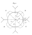
- rollers 3 1, 3 2 and 4 1, 4 2 have - as can be seen more clearly from FIG. 2 - fully cut caliber incisions which result in a cloverleaf caliber 5 with four bulges 5a which are assigned to the division planes E of the rolls.
- the rollers with their caliber-free tapered surfaces 6 are not adjustable against each other, which allows the rollers to be pretensioned. In the context of the invention, however, this is not absolutely necessary because - as shown in FIG. 1 - there can also be nips 7 between the pairs of rollers 3 and 4.
- the boundary surfaces 8 assigned to the bulges 5a of a cloverleaf caliber 5 are always assigned in terms of position to the division planes E or the roll gaps 7 and run symmetrically to these division planes or roll gaps.
- the boundary surfaces 8 of the bulges 5a are evenly curved with a radius of curvature 9 which is smaller than the distance 10 of the boundary surfaces 8 from the center of the caliber M.
- the working surfaces 12 of the recesses 5b of the trefoil caliber lying between the bulges 5a have a comparatively larger radius 5, which thus extend over a larger arc angle ⁇ than the sum of the adjacent portions of the boundary surfaces 8 of the bulges 5a of each roller. 2, the ratio between the radius of curvature 11 and the radius of curvature 9 is approximately 1.4: 1.
- the position of the center of curvature 13 for the radius of curvature 11 of the working surfaces 12 of the indentations 5b of each cloverleaf caliber 5 determine the decrease in height 14 with respect to the round inlet cross-section 15 indicated by dashed lines, which can be a tapping cross-section.
- the Ab Measurements of the cloverleaf caliber 5 are selected such that the boundary surfaces 8 of the bulges 5a run at a distance 10 from the center of the caliber M, which is the same or - as FIG. 2 shows - somewhat larger than the peripheral zone 15a of the inlet cross section 15 or 15 assigned to them of the pre-caliber.
- the circumferential zones of the inlet cross section 15 associated with the arc angle ⁇ and the decrease in height 14 are shown hatched in FIG. 2, which are subject to a strong compression deformation with a corresponding increase in length.
- no significant increases in width take place in the peripheral zones 15a of the inlet profile 15 in the region of the bulges 5a of the cloverleaf caliber 5, since the caliber 5 remains underfilled in the region of the boundary surfaces 8 of the bulges 5a, i. H. that there is no decrease in height here either.
- FIG. 3 shows the sequence of two cloverleaf calibers for four roller pairs 16 and 17, which also move together.
- the boundary surfaces 19 run in the region of the bulges 18a of the cut clover leaf caliber 18 symmetrically to the parting planes E of the roller pairs 16, 17 and at a greater distance from the center caliber M than the associated circumferential zones 20a of the clover leaf-shaped inlet cross-section 20 shown in broken lines the work surfaces 21 in the region of the bulges of the inlet cross-section 20 in the upstream roll stand run symmetrically to the parting planes E 1 thereof, the roller pairs 16, 17 according to FIG. 3 are offset by half the parting angle ⁇ compared to the roll pairs of the roughing stand, not shown.
- the sequence of cloverleaf calibers 20, 18 according to FIG. 3 clearly shows how large the sum of the compression-deformed, hatched zones whose partial increases in length radiate onto the areas of the caliber bulges 18.
- FIG. 4 shows a caliber sequence "cloverleaf-round", the cloverleaf-shaped inlet cross-section 22 shown in broken lines can be the outlet profile corresponding to the cloverleaf caliber 18 according to FIG. 3.
- the roller pairs 24 and 25 carrying the round profile 23 are again with their parting planes E2 by half the parting angle ⁇ compared to the parting planes E. of the roller pairs 16, 17 offset according to FIG. 3. It also applies to the circular caliber 23 that the boundary surfaces 26 assigned to the division planes E 2 run at the same or somewhat greater distance from the center of the caliber M than the peripheral surfaces of the inlet cross section 22 with the zone width 27 assigned to them.
- the round cross section leaving the roller pairs 24, 25, corresponding to the round caliber 23, can be a commercially available round finished cross section in diameter, so that it is advisable to arrange at least one round caliber as a sizing roll caliber in order to be able to subtract the finished cross section in a particularly close tolerance.
- FIG. 5 shows three rollers 30, 31, 32 which have been moved one on top of the other and into which a trefoil caliber 33 with three bulges 33a is cut.
- the inlet cross-section 34 shown in dashed lines is a round cross-section.
Landscapes
- Engineering & Computer Science (AREA)
- Mechanical Engineering (AREA)
- Metal Rolling (AREA)
- Reduction Rolling/Reduction Stand/Operation Of Reduction Machine (AREA)
- Control Of Metal Rolling (AREA)
- Crushing And Grinding (AREA)
- Registering, Tensioning, Guiding Webs, And Rollers Therefor (AREA)
Priority Applications (1)
| Application Number | Priority Date | Filing Date | Title |
|---|---|---|---|
| AT89107593T ATE78725T1 (de) | 1988-05-18 | 1989-04-27 | Kalibrierung fuer die walzen von walzgeruesten mit drei oder mehr walzen. |
Applications Claiming Priority (2)
| Application Number | Priority Date | Filing Date | Title |
|---|---|---|---|
| DE3816840A DE3816840A1 (de) | 1988-05-18 | 1988-05-18 | Kalibrierung fuer die walzen von walzgeruesten mit drei oder mehr walzen |
| DE3816840 | 1988-05-18 |
Publications (3)
| Publication Number | Publication Date |
|---|---|
| EP0342403A2 true EP0342403A2 (fr) | 1989-11-23 |
| EP0342403A3 EP0342403A3 (en) | 1990-06-13 |
| EP0342403B1 EP0342403B1 (fr) | 1992-07-29 |
Family
ID=6354581
Family Applications (1)
| Application Number | Title | Priority Date | Filing Date |
|---|---|---|---|
| EP89107593A Expired - Lifetime EP0342403B1 (fr) | 1988-05-18 | 1989-04-27 | Calibrage pour les cylindres des cages de laminoir avec trois ou plusieurs des cylindres |
Country Status (4)
| Country | Link |
|---|---|
| EP (1) | EP0342403B1 (fr) |
| JP (1) | JPH0215810A (fr) |
| AT (1) | ATE78725T1 (fr) |
| DE (2) | DE3816840A1 (fr) |
Cited By (5)
| Publication number | Priority date | Publication date | Assignee | Title |
|---|---|---|---|---|
| EP0368049A3 (fr) * | 1988-11-10 | 1991-07-24 | Sms Schloemann-Siemag Aktiengesellschaft | Calibrage pour les cylindres de cages de laminoir à trois ou plusieurs cylindres |
| EP0850701A1 (fr) * | 1996-12-23 | 1998-07-01 | Sms Schloemann-Siemag Aktiengesellschaft | Procédé et installation de production de barres avec une structure affinée et/ou compressée par forgeage au laminoir |
| EP0865836A3 (fr) * | 1997-03-20 | 1999-04-14 | Techint Compagnia Tecnica Internazionale S.P.A. | Train de laminage et procédé de laminage correspondant à rendement amélioré |
| WO2003082659A1 (fr) * | 2002-03-27 | 2003-10-09 | Dynamet Holdings, Inc. | Glissiere pour selle de bicyclette et procede de fabrication |
| WO2017147430A1 (fr) * | 2016-02-25 | 2017-08-31 | Unarco Industries Llc | Dispositif pour la formation de fil rainuré |
Family Cites Families (5)
| Publication number | Priority date | Publication date | Assignee | Title |
|---|---|---|---|---|
| DE26893C (de) * | GEBR. SCHMIDT in Schwelm | Drahtwalzwerk, bestehend aus vier Walzen mit cannelirtem Kaliber | ||
| DE23230C (de) * | GEBRÜDER SCHMIDT in Schwelm, Westfalen | Drahtwalzwerk, bestehend aus drei Walzen mit canelirtem Kaliber | ||
| FR532438A (fr) * | 1920-09-16 | 1922-02-03 | Procédé de fabrication de fils et barres métalliques | |
| DE2035482C2 (de) * | 1968-12-12 | 1983-01-20 | Kocks Technik Gmbh & Co, 4010 Hilden | Walzenkalibrierung für Feineisen-, insbesondere für Drahtwalzstraßen |
| DE2462279B2 (de) * | 1974-04-17 | 1977-05-18 | Ausscheidung aus: 24 18 453 Schloemann Siemag AG, 4000 Düsseldorf | Verfahren und vorrichtung zum herstellen von achtkantquerschnitten als ausgangsmaterial fuer das walzen auf schraegwalzwerken mit planetenantrieb |
-
1988
- 1988-05-18 DE DE3816840A patent/DE3816840A1/de not_active Withdrawn
-
1989
- 1989-04-27 EP EP89107593A patent/EP0342403B1/fr not_active Expired - Lifetime
- 1989-04-27 DE DE8989107593T patent/DE58901922D1/de not_active Expired - Lifetime
- 1989-04-27 AT AT89107593T patent/ATE78725T1/de not_active IP Right Cessation
- 1989-05-18 JP JP1123006A patent/JPH0215810A/ja active Pending
Cited By (8)
| Publication number | Priority date | Publication date | Assignee | Title |
|---|---|---|---|---|
| EP0368049A3 (fr) * | 1988-11-10 | 1991-07-24 | Sms Schloemann-Siemag Aktiengesellschaft | Calibrage pour les cylindres de cages de laminoir à trois ou plusieurs cylindres |
| EP0850701A1 (fr) * | 1996-12-23 | 1998-07-01 | Sms Schloemann-Siemag Aktiengesellschaft | Procédé et installation de production de barres avec une structure affinée et/ou compressée par forgeage au laminoir |
| EP0865836A3 (fr) * | 1997-03-20 | 1999-04-14 | Techint Compagnia Tecnica Internazionale S.P.A. | Train de laminage et procédé de laminage correspondant à rendement amélioré |
| US6128939A (en) * | 1997-03-20 | 2000-10-10 | Techint Compagnia Tecnica Internazionale S.P.A. | Roll train and the relative rolling process with an improved yield |
| WO2003082659A1 (fr) * | 2002-03-27 | 2003-10-09 | Dynamet Holdings, Inc. | Glissiere pour selle de bicyclette et procede de fabrication |
| WO2017147430A1 (fr) * | 2016-02-25 | 2017-08-31 | Unarco Industries Llc | Dispositif pour la formation de fil rainuré |
| US20170246669A1 (en) * | 2016-02-25 | 2017-08-31 | Unarco Industries Llc | Grooved wire and system and method for manufacturing grooved wire |
| US10766060B2 (en) * | 2016-02-25 | 2020-09-08 | Unarco Industries Llc | Grooved wire and system and method for manufacturing grooved wire |
Also Published As
| Publication number | Publication date |
|---|---|
| ATE78725T1 (de) | 1992-08-15 |
| DE3816840A1 (de) | 1989-11-30 |
| EP0342403A3 (en) | 1990-06-13 |
| DE58901922D1 (de) | 1992-09-03 |
| JPH0215810A (ja) | 1990-01-19 |
| EP0342403B1 (fr) | 1992-07-29 |
Similar Documents
| Publication | Publication Date | Title |
|---|---|---|
| DE3038865C1 (de) | Walzgeruest mit axial verschiebbaren Walzen | |
| DE2714485C2 (de) | Verfahren zum Warmwalzen von Doppel-T-Trägern aus rechteckigem Flachmaterial | |
| EP0256409B2 (fr) | Procédé de fabrication de profils | |
| DE68905679T2 (de) | Verfahren zum walzen von doppel-t-stahlprofilen. | |
| DE2437545C3 (de) | Verfahren zum Walzen von Metallstäben | |
| DE1452020A1 (de) | Verfahren zum Walzen von Schienenprofilen | |
| DE69204545T2 (de) | Verfahren zur Herstellung von Profilen und/oder Stäben im kalten Zustand. | |
| DE2114346A1 (de) | Verfahren und Vorrichtung zum Vorwalzen von Brammen bezueglich ihrer Breite | |
| DE2522070A1 (de) | Walzgutfuehrung fuer ein walzgeruest | |
| EP0342403B1 (fr) | Calibrage pour les cylindres des cages de laminoir avec trois ou plusieurs des cylindres | |
| DE2119347A1 (de) | Verfahren zur kontinuierlichen Warmverformung von kontinuierlich gegossenen Stahlsträngen | |
| DE1912350A1 (de) | Verfahren zum Walzen von Stahl-Flanschwerkstuecken sowie Walzengeruest zur Durchfuehrung dieses Verfahrens | |
| AT393805B (de) | Verfahren zur herstellung von gestaengerohren und dorn- oder stopfenloses schraegwalzgeruest zur durchfuehrung des verfahrens | |
| EP0255714A2 (fr) | Laminoir à cylindres multiples avec des cylindres intermédiaires déplaçables axialement et aux extrémités coniques | |
| DE2542313A1 (de) | Verfahren zum walzen metallischer rohlinge | |
| DE29780451U1 (de) | Hochgenaues Walzwerk mit zweidimensionaler Biegungssteuerung | |
| DE29980239U1 (de) | Walzwerk mit zweidimensional gesteuerter Walzendurchbiegung | |
| DE2524224A1 (de) | Verfahren und vorrichtung zum walzen von stabstahl | |
| DE538630C (de) | Fuehrungseinrichtung fuer die einzelnen Staender von kontinuierlichen Blech- und Streifenwalzwerken | |
| DE3302333C2 (fr) | ||
| DE69623208T2 (de) | Verfahren und vorrichtung zum warmwalzen von h-stahlträgern | |
| DE2462279A1 (de) | Verfahren und vorrichtung zum herstellen von achtkantquerschnitten als ausgangsmaterial fuer das walzen auf schraegwalzwerken mit planetenantrieb | |
| DE575529C (de) | Pilgerwalzenkaliber | |
| DE625129C (de) | Verfahren zum Auswalzen von Blech aus einer konischen Bramme | |
| DE1010937B (de) | Verfahren und Vorrichtung zum Warmwalzen eines metallischen, halbflachen Werkstueckes in eine Stange mit trapezfoermigem Querschnitt |
Legal Events
| Date | Code | Title | Description |
|---|---|---|---|
| PUAI | Public reference made under article 153(3) epc to a published international application that has entered the european phase |
Free format text: ORIGINAL CODE: 0009012 |
|
| 17P | Request for examination filed |
Effective date: 19890519 |
|
| AK | Designated contracting states |
Kind code of ref document: A2 Designated state(s): AT CH DE GB IT LI SE |
|
| PUAL | Search report despatched |
Free format text: ORIGINAL CODE: 0009013 |
|
| AK | Designated contracting states |
Kind code of ref document: A3 Designated state(s): AT CH DE GB IT LI SE |
|
| 17Q | First examination report despatched |
Effective date: 19910531 |
|
| GRAA | (expected) grant |
Free format text: ORIGINAL CODE: 0009210 |
|
| AK | Designated contracting states |
Kind code of ref document: B1 Designated state(s): AT CH DE GB IT LI SE |
|
| PG25 | Lapsed in a contracting state [announced via postgrant information from national office to epo] |
Ref country code: IT Free format text: LAPSE BECAUSE OF FAILURE TO SUBMIT A TRANSLATION OF THE DESCRIPTION OR TO PAY THE FEE WITHIN THE PRE;WARNING: LAPSES OF ITALIAN PATENTS WITH EFFECTIVE DATE BEFORE 2007 MAY HAVE OCCURRED AT ANY TIME BEFORE 2007. THE CORRECT EFFECTIVE DATE MAY BE DIFFERENT FROM THE ONE RECORDED.SCRIBED TIME-LIMIT Effective date: 19920729 Ref country code: GB Effective date: 19920729 Ref country code: SE Effective date: 19920729 |
|
| REF | Corresponds to: |
Ref document number: 78725 Country of ref document: AT Date of ref document: 19920815 Kind code of ref document: T |
|
| REF | Corresponds to: |
Ref document number: 58901922 Country of ref document: DE Date of ref document: 19920903 |
|
| GBV | Gb: ep patent (uk) treated as always having been void in accordance with gb section 77(7)/1977 [no translation filed] |
Effective date: 19920729 |
|
| PG25 | Lapsed in a contracting state [announced via postgrant information from national office to epo] |
Ref country code: AT Effective date: 19930427 |
|
| PG25 | Lapsed in a contracting state [announced via postgrant information from national office to epo] |
Ref country code: CH Effective date: 19930430 Ref country code: LI Effective date: 19930430 |
|
| PLBE | No opposition filed within time limit |
Free format text: ORIGINAL CODE: 0009261 |
|
| STAA | Information on the status of an ep patent application or granted ep patent |
Free format text: STATUS: NO OPPOSITION FILED WITHIN TIME LIMIT |
|
| 26N | No opposition filed | ||
| REG | Reference to a national code |
Ref country code: CH Ref legal event code: PL |
|
| PGFP | Annual fee paid to national office [announced via postgrant information from national office to epo] |
Ref country code: DE Payment date: 19950621 Year of fee payment: 7 |
|
| PG25 | Lapsed in a contracting state [announced via postgrant information from national office to epo] |
Ref country code: DE Effective date: 19970101 |